CN201364890Y - Portable suction pen for semiconductor electronic industry - Google Patents
Portable suction pen for semiconductor electronic industry Download PDFInfo
- Publication number
- CN201364890Y CN201364890Y CNU200920088691XU CN200920088691U CN201364890Y CN 201364890 Y CN201364890 Y CN 201364890Y CN U200920088691X U CNU200920088691X U CN U200920088691XU CN 200920088691 U CN200920088691 U CN 200920088691U CN 201364890 Y CN201364890 Y CN 201364890Y
- Authority
- CN
- China
- Prior art keywords
- turbine
- battery
- casing
- pen
- shell
- Prior art date
- Legal status (The legal status is an assumption and is not a legal conclusion. Google has not performed a legal analysis and makes no representation as to the accuracy of the status listed.)
- Expired - Fee Related
Links
Images
Abstract
The utility model relates to a portable suction pen for semiconductor electronic industry. With the portable suction pen, grain crystals can be sucked at any time without requiring extra vacuum source for supply vacuum, and the operational convenience and work efficiency are improved. The technical scheme includes that an inner seal tube is mounted in a casing, the upper part of the inner seal tube is mounted with a turbine through a seal ring, a battery is mounted in the casing on the upper part of the turbine, an air flowing port and a battery power switch are machined on the casing between the battery and the turbine, an air outlet on the upper part of the turbine is communicated with the air flowing port, the battery is communicated with the turbine through conducting wires, a suction head is arranged on the lower part of the casing, an airflow chamber is formed between the inner seal tube on the lower part of the turbine and the suction head, air holes communicated with the airflow chamber are machined on the inner seal tube and the casing; the portable suction pen for semiconductor electronic industry has simple structure, ingenious design, and convenient use and carrying, can effectively solve the crystal taking and placing problems in crystal component production, has high production efficiency, and has good economic and social benefits.
Description
One, technical field
The utility model relates to electronic device, draws the portable suction pen of semi-conductor electricity sub-industry that crystal grain is used in particularly a kind of manufacture of semiconductor.
Two, background technology
The used suction pen of semiconductor industry mainly is to provide negative pressure to realize drawing the operation of device by vacuum source at present.Fig. 1 is that tradition is inhaled pen use schematic diagram, vacuum source is produced by vacuum system and provides along vacuum pipe, generally have only Production Regional that vacuum source is just arranged, and in other places, as: office, laboratory or some nonproductive zones, vacuum source is not set, therefore can't uses in these places; In addition, traditional suction pen need be connected to from vacuum source with pvc pipe inhales pen, poor mobility, and directly influence the convenience and the operating efficiency of operation, to often solve long too short, the problem such as placement location is bad of pvc pipe simultaneously, constantly prevent some accident potential of being prone to, run into product as pvc pipe in using.In addition, for some middle-size and small-size factories or little unit such as the laboratory of some consumptions, setting up expensive vacuum system and pipeline does not possess economic condition at first stage of construction, therefore, is to be concerned about the technical problem that will solve in the industry to the improvement and the innovation of inhaling pen.
Three, utility model content
In view of the above-mentioned problems, for overcoming the prior art defective, the purpose of the utility model just provides the portable suction pen of a kind of semi-conductor electricity sub-industry, or else can effectively solve needs other vacuum source supply vacuum just can draw crystal grain at any time, strengthen the convenience of operation, the problem of increasing work efficiency, the technical scheme of its solution is, for solving the art problem, the utility model is according to following principle, the centrifugal fan of turbine rotates, and the air of pipe reduces in making, and just begins inwardly to manage moving air at the suction nozzle position of inhaling pen simultaneously, press...with one's finger and inhale the middle air-breathing sky of pen, when object (crystal grain) sheltered from the position of suction nozzle, interior pipe just formed reverse pneumatics, thereby with die pick; In the time of the crystal grain that picks up will being put down, can unclamp the finger of inhaling the middle air-breathing sky of pen, reduce to manage interior pneumatics, can realize the placement of crystal grain.Whole process realizes picking up and placing of crystal grain by the rotation of turbine centrifugal fan, in view of the above, structure of the present utility model is, interior sealed tube is housed in the shell, turbine is equipped with through sealing ring in interior sealed tube top, in the shell on turbine top battery is housed, there is free air-flow to open one's mouth and battery power switch on the shell between battery and the turbine, turbine top air outlet is connected with the air flows mouth, and battery is connected with turbine through lead, and outer casing underpart has suction nozzle, constitute airflow chamber between the interior sealed tube of turbine bottom and the suction nozzle, the pore that is communicated with airflow chamber is arranged on interior sealed tube and the shell, and the utility model is simple in structure, and is novel unique, portably use conveniently, can effectively solve in the quartz crystal device production the picking up and the placement problem of crystal, the production efficiency height has good economic and social benefit.
Four, description of drawings
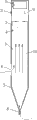
Fig. 1 is a structure chart of the present utility model.
Fig. 2 is an air-flow direction schematic diagram in the work of the present utility model.
Five, embodiment
Below in conjunction with accompanying drawing embodiment of the present utility model is elaborated.
Provide by Fig. 1, sealed tube 5 in being equipped with in the utility model shell 7, turbine 3 is equipped with through sealing ring 4 in interior sealed tube top, battery 1 is housed in the shell on turbine top, there is free air-flow to open one's mouth 9 and battery power switch 2 on the shell between battery and the turbine, turbine top air outlet is connected with air flows mouth 9, battery is connected with turbine through lead, outer casing underpart has suction nozzle 8, constitute airflow chamber 10 between the interior sealed tube 5 of turbine 3 bottoms and the suction nozzle, the pore 6 that is communicated with airflow chamber 10 is arranged on interior sealed tube and the shell.
For easy to use and increase work efficiency, said shell 7 is rounded, and it is conical that its underpart is, and on the conical thin end suction nozzle 8 arranged; The round rubber suction nozzle (not indicating among the suction nozzle figure) of different cross-sectional can be housed, to satisfy the crystal grain of different size on the said suction nozzle 8.
Working condition of the present utility model is (arrow is depicted as the flow direction of air-flow among the figure) as shown in Figure 2:
A, die pick (absorption): when switching battery mains switch 2 is pressed, just begin rotation after turbine 3 energisings, the air of interior sealed tube 5 is emitted by air flows mouth 9, the air that interior sealed tube is 5 li is owing to needing after being emitted by turbine by pore 6 and suction nozzle 8 past interior sealed tubes conveyings, operating personnel held with pen holding posture and inhaled pen this moment, block the position of pore 6 with forefinger, after hold and inhale pen and be put into grain surface, because the Pneumatic action in the pipe, this moment, crystal grain will be held the position at suction nozzle 8, thereby make crystal grain picked, owing to suction nozzle 8 positions are blocked by crystal grain, can not be toward interior pipe moving air.
B, placement: after will inhaling pen and moving on to the position that will place, can unclamp the forefinger of pore 6 positions, sealed tube is full of moving air in this moment, and crystal grain can come off under the situation without any suction automatically, to realize the placement of crystal grain.
From the above, this practicality newly can be implemented in quickly and easily in the manufacture of semiconductor to crystal grain pick up and place, be the improvement of drawing a suction novelty of crystal grain device to existing.
Claims (3)
1, the portable suction pen of a kind of semi-conductor electricity sub-industry, it is characterized in that, interior sealed tube (5) is housed in the shell (7), turbine (3) is equipped with through sealing ring (4) in interior sealed tube top, battery (1) is housed in the shell on turbine top, there is free air-flow to open one's mouth (9) and battery power switch (2) on the shell between battery and the turbine, turbine top air outlet is connected with air flows mouth (9), battery is connected with turbine through lead, outer casing underpart has suction nozzle (8), constitute airflow chamber (10) between the interior sealed tube (5) of turbine (3) bottom and the suction nozzle, have on interior sealed tube and the shell and pore (6) that airflow chamber (10) is communicated with.
2, the portable suction pen of semi-conductor electricity sub-industry according to claim 1 is characterized in that, said shell (7) is rounded, and it is conical that its underpart is, and suction nozzle (8) is arranged on the conical thin end.
3, the portable suction pen of semi-conductor electricity sub-industry according to claim 1 is characterized in that, the round rubber suction nozzle of different cross-sectional is housed on the said suction nozzle (8).
Priority Applications (1)
| Application Number | Priority Date | Filing Date | Title |
|---|---|---|---|
| CNU200920088691XU CN201364890Y (en) | 2009-02-26 | 2009-02-26 | Portable suction pen for semiconductor electronic industry |
Applications Claiming Priority (1)
| Application Number | Priority Date | Filing Date | Title |
|---|---|---|---|
| CNU200920088691XU CN201364890Y (en) | 2009-02-26 | 2009-02-26 | Portable suction pen for semiconductor electronic industry |
Publications (1)
| Publication Number | Publication Date |
|---|---|
| CN201364890Y true CN201364890Y (en) | 2009-12-16 |
Family
ID=41475561
Family Applications (1)
| Application Number | Title | Priority Date | Filing Date |
|---|---|---|---|
| CNU200920088691XU Expired - Fee Related CN201364890Y (en) | 2009-02-26 | 2009-02-26 | Portable suction pen for semiconductor electronic industry |
Country Status (1)
| Country | Link |
|---|---|
| CN (1) | CN201364890Y (en) |
Cited By (2)
| Publication number | Priority date | Publication date | Assignee | Title |
|---|---|---|---|---|
| CN107728281A (en) * | 2017-11-07 | 2018-02-23 | 辽宁中蓝电子科技有限公司 | A kind of anti-dazzling screen assembling wand |
| CN108376667A (en) * | 2018-04-23 | 2018-08-07 | 宁波市中迪工贸有限公司 | Small-sized electric wand |
-
2009
- 2009-02-26 CN CNU200920088691XU patent/CN201364890Y/en not_active Expired - Fee Related
Cited By (2)
| Publication number | Priority date | Publication date | Assignee | Title |
|---|---|---|---|---|
| CN107728281A (en) * | 2017-11-07 | 2018-02-23 | 辽宁中蓝电子科技有限公司 | A kind of anti-dazzling screen assembling wand |
| CN108376667A (en) * | 2018-04-23 | 2018-08-07 | 宁波市中迪工贸有限公司 | Small-sized electric wand |
Similar Documents
| Publication | Publication Date | Title |
|---|---|---|
| CN205699839U (en) | A kind of cleaner unit structure integrating pressure-vaccum function | |
| CN203564662U (en) | Filtration breathing machine | |
| CN201364890Y (en) | Portable suction pen for semiconductor electronic industry | |
| CN204427940U (en) | Multifunctional dust vacuum cleaner | |
| CN201658327U (en) | Water-gas separating type dust collector with water throwing device | |
| CN208077954U (en) | A kind of novel sheet suction means | |
| CN202128718U (en) | Feeding bottle capable of returning air automatically | |
| CN203356164U (en) | Peripheral dust suction hood and dust collector provided with same | |
| CN206046584U (en) | A kind of air-flowing type computer keyboard cleaning plant | |
| CN203292132U (en) | Dust sucking device | |
| CN203763005U (en) | Dust collector for clearing away dust in thin groove | |
| CN209408282U (en) | A kind of processing thin-walled parts negative pressure of vacuum adsorption tooling | |
| CN203212704U (en) | Dust collecting device for spinning machine | |
| CN207094842U (en) | Energy-saving purifier | |
| CN208770477U (en) | A kind of easy Medical sputum aspiration device | |
| CN206179890U (en) | Novel photovoltaic cell cluster absorb device | |
| CN204033242U (en) | A kind of air blowing syndeton of dust catcher | |
| CN204056373U (en) | Jetting stream vacuum machine | |
| CN203029926U (en) | Ping-pong ball sucking device | |
| CN204257613U (en) | Combined solar silicon wafers inhales pen | |
| CN201430156Y (en) | Silicon chip suction and discharge pen | |
| CN204271060U (en) | A kind of silicon chip fetching device | |
| CN202574741U (en) | Novel paste labeling machine | |
| CN202950611U (en) | Small self-made dust collector | |
| CN208698297U (en) | A kind of dust-proof environment protection blackboard |
Legal Events
| Date | Code | Title | Description |
|---|---|---|---|
| C14 | Grant of patent or utility model | ||
| GR01 | Patent grant | ||
| C17 | Cessation of patent right | ||
| CF01 | Termination of patent right due to non-payment of annual fee |
Granted publication date: 20091216 Termination date: 20120226 |