CN201360261Y - FM antenna and terminal - Google Patents
FM antenna and terminal Download PDFInfo
- Publication number
- CN201360261Y CN201360261Y CNU2009201059488U CN200920105948U CN201360261Y CN 201360261 Y CN201360261 Y CN 201360261Y CN U2009201059488 U CNU2009201059488 U CN U2009201059488U CN 200920105948 U CN200920105948 U CN 200920105948U CN 201360261 Y CN201360261 Y CN 201360261Y
- Authority
- CN
- China
- Prior art keywords
- antenna
- insulated wire
- frequency
- enamel insulated
- connecting line
- Prior art date
- Legal status (The legal status is an assumption and is not a legal conclusion. Google has not performed a legal analysis and makes no representation as to the accuracy of the status listed.)
- Expired - Fee Related
Links
Images
Abstract
The utility model discloses a FM antenna and a terminal, relates to communication technical field and solves the problem that mobile phones can be used for receiving FM broadcast only through the wired earphone connection establishment mode. The terminal comprises an internal FM antenna; the main body structure of the FM antenna is divided into two parts, wherein one part is wrapped by first enamel insulated wire, the other part is wrapped by second enamel insulated wire with diameter different from that of the first enamel insulated wire, the first enamel insulated wire extends to form a first connecting wire in the joint part of the two parts, the second enamel insulated wire extends to form a second connecting wire in the joint part of the two parts. The FM antenna and terminal are mainly applicable to situations of receiving FM broadcast.
Description
Technical field
The utility model relates to communication technical field, relates in particular to a kind of FM frequency-modulated antenna and a kind of terminal.
Background technology
FM fm broadcast receiver (being broadcast receiver) is very ripe through the development of many decades.The antenna of traditional desk-top civilian FM fm broadcast receiver adopts external rod-pulling type antenna or built-in Wound-rotor type antenna usually.
In the last few years, along with the develop rapidly of mobile communication technology, many portable terminals, for example: the function of FM fm broadcast receiver that mobile phone is all integrated.Compare with traditional desk-top civilian FM fm broadcast receiver, the volume of mobile phone is much smaller, antenna on the mobile phone of like this small size is if satisfy simultaneously and have the electric wave reception of FM FM broadcasting or emission function and the little characteristics of volume, and a kind of scheme commonly used at present is: mobile phone uses wired earphone to receive as FM FM broadcasting electric wave or the antenna of emission.This scheme is equivalent to a kind of improvement of the external rod-pulling type antenna of traditional desk-top civilian FM fm broadcast receiver.
At the mobile phone that adopts this scheme to realize with FM fm broadcast receiver function, the user just can listen to the FM FM broadcasting after wired earphone must being connected to mobile phone, and the length of wired earphone is 75cm-80cm usually, tediously long connecting line is easy to bring inconvenience to the user when using earphone, also makes the user can't be by the broadcast mode uppick FM FM broadcasting of putting simultaneously outward.
The utility model content
The utility model provides a kind of FM frequency-modulated antenna and terminal.Not needing to realize by connecting reception of FM frequency modulation broadcast system or the emission electric wave that wired earphone just can make mobile phone.
For achieving the above object, the utility model adopts following technical scheme:
A kind of FM frequency-modulated antenna, comprise the antenna body structure, described antenna body structure is divided into two parts, wherein a part is holding first enamel insulated wire, another part is holding and the second different enamel insulated wire of the described first enamel insulated wire diameter, and described first enamel insulated wire extends first connecting line in two-part junction, and described second enamel insulated wire extends second connecting line in two parts junction.
Further, FM frequency-modulated antenna provided by the utility model also comprises: antenna is linked into circuit by described first connecting line and described second connecting line; And described first connecting line is connected with the feed that described second connecting line is connected on the circuit jointly; In the upper end of described antenna body structure, lower end, and the projection of use when respectively having a section to cooperate fixedly in described two-part junction; The cylinder of antenna body structure described in the utility model for making by three kinds of material mixing.
A kind of terminal, comprise built-in FM frequency-modulated antenna, described FM frequency-modulated antenna agent structure is divided into two parts, wherein a part is holding first enamel insulated wire, another part is holding and the second different enamel insulated wire of the described first enamel insulated wire diameter, and described first enamel insulated wire extends first connecting line in two-part junction, and described second enamel insulated wire extends second connecting line in two parts junction.
Further, terminal provided by the utility model also comprises: by described first connecting line and described second connecting line jointly with circuit on the described FM frequency-modulated antenna that is connected of a feed tie point be linked into described circuit; In the upper end of described FM frequency-modulated antenna agent structure, lower end, and the projection of use when respectively having a section to cooperate fixedly in described two-part junction; And the cylinder of described FM frequency-modulated antenna agent structure for making by three kinds of material mixing; Terminal described in the utility model is a portable terminal, and described portable terminal comprises: mobile phone, walkman, MP4, MP5.
The technical solution of the utility model is based on a kind of improvement of the built-in Wound-rotor type antenna of traditional desk-top civilian FM fm broadcast receiver.Can guarantee the normal beneficial effect that receives or launch broadcasting wave of antenna by adopting miniaturization technology, having obtained.Simultaneously, built-in terminal of the present utility model, mobile phone for example can make the user save the process that must connect with wired earphone when utilizing this mobile phone to listen to the FM FM broadcasting, promptly increased the availability when listening to the FM FM broadcasting, brought favorable experience to the user again by mobile phone.
Description of drawings
In order to be illustrated more clearly in the utility model embodiment or technical scheme of the prior art, to do to introduce simply to the accompanying drawing of required use in embodiment or the description of the Prior Art below, apparently, accompanying drawing in describing below only is embodiment more of the present utility model, for those of ordinary skills, under the prerequisite of not paying creative work, can also obtain other accompanying drawing according to these accompanying drawings.
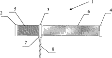
Fig. 1 is the front view of the utility model embodiment 1FM frequency-modulated antenna.
Embodiment
Present embodiment discloses a kind of FM frequency-modulated antenna, this FM frequency-modulated antenna comprises the antenna body structure, this antenna body structure is divided into two parts, wherein a part is holding first enamel insulated wire, another part is holding second enamel insulated wire different with this first enamel insulated wire diameter, and this first enamel insulated wire extends first connecting line in two-part junction, and this second enamel insulated wire extends second connecting line in two parts junction.
In addition, present embodiment also discloses a kind of terminal, this terminal comprises built-in FM frequency-modulated antenna, this FM frequency-modulated antenna agent structure is divided into two parts, wherein a part is holding first enamel insulated wire, another part is holding second enamel insulated wire different with this first enamel insulated wire diameter, and this first enamel insulated wire extends first connecting line in two-part junction, and this second enamel insulated wire extends second connecting line in two parts junction.
Below in conjunction with the accompanying drawing among the utility model embodiment, the technical scheme among the utility model embodiment is clearly and completely described, obviously, described embodiment only is the utility model part embodiment, rather than whole embodiment.Based on the embodiment in the utility model, those of ordinary skills are not making the every other embodiment that is obtained under the creative work prerequisite, all belong to the scope of the utility model protection.
Present embodiment provides a kind of FM frequency-modulated antenna, as shown in Figure 1, comprise antenna body structure 1, this antenna body structure 1 is antenna coiling inner core, be by acrylonitrile-butadiene-styrene copolymer plastics (abbreviation ABS plastic), the cylinder that Polycarbonate plastics (being called for short the PC plastics) and high permeability material are mixed and made into by a certain percentage, described cylindrical height is about 48 ± 0.1mm, diameter is about 4 ± 0.1mm, one section projection 2 is arranged in the upper end of this antenna body structure 1, one section projection 4 is arranged in the lower end of antenna body structure 1, the height of projection 2 and projection 4 is (height of projection 2 and projection 4 is included in the height 48 ± 0.1mm of antenna body structure 1 in the present embodiment) about 1 ± 0.1mm, and the barrel portion diameter corresponding with the height of projection 2 is about 5 ± 0.1mm.Similarly, corresponding with the height of projection 4 barrel portion diameter also is about 5 ± 0.1mm.Projection 2 and projection 4 are used for the FM frequency-modulated antenna of present embodiment is fixed on a certain appropriate location of terminal inner.
For the inside that is fixed on terminal that the FM frequency-modulated antenna is more stable, also comprise projection 3 on the antenna body structure 1 in the present embodiment.In the present embodiment, projection 3 is positioned at apart from 14 ± 0.1mm place of the upper end of antenna body structure 1, the same with projection 2, highly be (height of projection 3 is included in the height 48 ± 0.1mm of antenna body structure 1 in the present embodiment) about 1 ± 0.1mm, the barrel portion diameter corresponding with protruding 3 is about 5 ± 0.1mm.Projection 3 is fixed on the inside of terminal with projection 2, projection 4 with antenna, is used to guarantee the stability of antenna at terminal inner.
Two parts have been divided into by protruding 3 antenna body structures 1, part 5 and part 6, wherein part 5 is between projection 2 and projection 3, part 5 highly is about 13 ± 0.1mm, holding diameter on part 5 is first enamel insulated wire of 0.15 ± 0.02mm, and this first enamel insulated wire extends one section first connecting line 7 at an end that closes on protruding 3 places; Part 6 is between projection 3 and projection 4, part 6 highly is about 32 ± 0.1mm, holding diameter on part 6 is second enamel insulated wire of 0.35 ± 0.02mm, this second enamel insulated wire extends one section second connecting line 8 at an end that closes on protruding 3 places, first connecting line 7 is connected to a feed tie point on the circuit with second connecting line 8, by a described feed tie point that is connected to, the FM frequency-modulated antenna in the present embodiment just can be set up and being connected of circuit.
The FM frequency-modulated antenna that present embodiment provides has following beneficial effect: the antenna coiling inner core that adopts three kinds of composite materials to make has structure firmly, easily to be assembled electromagnetic field and reduces advantages such as number of turns and antenna volume, the antenna body structure is unit with the millimeter under the condition that can guarantee the antenna service behaviour, the volume miniaturization, be fit to be built in the terminal, the less portable terminal of volume particularly, as mobile phone, can make mobile phone not need just can realize the reception or the emission of FM FM broadcasting electric wave by wired earphone; Compare with the antenna of duplex feeding tie point of the prior art, the FM frequency-modulated antenna in the present embodiment can connect with circuit by a feed tie point, the quantity of the feed tie point that need connect when having reduced place in circuit.
Present embodiment provides a kind of mobile phone, this mobile phone has the FM frequency modulation broadcast function, especially, also built-in FM frequency-modulated antenna in this mobile phone, as shown in Figure 1, this FM frequency-modulated antenna comprises antenna body structure 1, this antenna body structure 1 is antenna coiling inner core, be by acrylonitrile-butadiene-styrene copolymer plastics (abbreviation ABS plastic), the cylinder that Polycarbonate plastics (being called for short the PC plastics) and high permeability material are mixed and made into by a certain percentage, described cylindrical height is about 48 ± 0.1mm, diameter is about 4 ± 0.1mm, one section projection 2 is arranged in the upper end of this antenna body structure 1, one section projection 4 is arranged in the lower end of antenna body structure 1, the height of projection 2 and projection 4 is (height of projection 2 and projection 4 is included in the height 48 ± 0.1mm of antenna body structure 1 in the present embodiment) about 1 ± 0.1mm, and the barrel portion diameter corresponding with the height of projection 2 is about 5 ± 0.1mm.Similarly, corresponding with the height of projection 4 barrel portion diameter also is about 5 ± 0.1mm.This projection 2 and projection 4 are used for matching with the buckle of mobile phone inside, play the effect that the FM antenna is fixed on mobile phone inside.
For the inside that is fixed on mobile phone that the FM frequency-modulated antenna is more stable, also comprise projection 3 on the antenna body structure 1 in the present embodiment.In the present embodiment, projection 3 is positioned at apart from 14 ± 0.1mm place of the upper end of antenna body structure 1, the same with projection 2, highly be (projection 3 highly is also contained in the height 48 ± 0.1mm of antenna body structure 1 in the present embodiment) about 1 ± 0.1mm, the barrel portion diameter corresponding with protruding 3 is about 5 ± 0.1mm.Projection 3 is fixed on the inside of terminal with projection 2, projection 4 with antenna, is used to guarantee the stability of antenna at terminal inner.
By projection 3, antenna body structure 1 has been divided into two parts, part 5 and part 6, wherein part 5 is between projection 2 and projection 3, part 5 highly is about 13 ± 0.1mm, holding diameter on part 5 is first enamel insulated wire of 0.15 ± 0.02mm, and this first enamel insulated wire extends one section first connecting line 7 at an end that closes on protruding 3 places; Part 6 is between projection 3 and projection 4, part 6 highly is about 32 ± 0.1mm, holding diameter on part 6 is second enamel insulated wire of 0.35 ± 0.02mm, this second enamel insulated wire extends one section second connecting line 8 at an end that closes on protruding 3 places, first connecting line 7 is connected to a feed tie point on the circuit with second connecting line 8, by a described feed tie point, the FM frequency-modulated antenna in the present embodiment just can be set up and being connected of mobile phone circuit.
Performance when the mobile phone of the built-in FM frequency-modulated antenna in the present embodiment is received the FM FM broadcasting and has been carried out contrast test by wired earphone as the performance of mobile phone when receiving the FM FM broadcasting of antenna, and this test result is as shown in the table:

Test data from above table as can be known, the mobile phone of the built-in FM frequency-modulated antenna that present embodiment provides be suitable by wired earphone as the mobile phone of the antenna performance when receiving FM FM broadcasting electric wave.The reciprocity of parameter constant when having reception done or emission because of antenna in addition is so the FM frequency-modulated antenna in the present embodiment equally also can be launched the electric wave of FM FM broadcasting.
The mobile phone that present embodiment provided is by the technical scheme of the FM frequency-modulated antenna of the built-in miniaturization of employing, solved in the prior art, the user must be by the technical problem of wired earphone when listening to the FM FM broadcasting by mobile phone, obtained and need not the beneficial effect that wired earphone just can directly be listened to the FM FM broadcasting, also increased simultaneously the availability the when user listens to the FM FM broadcasting by mobile phone, brought favorable experience to the user.
The above; it only is embodiment of the present utility model; but protection range of the present utility model is not limited thereto; anyly be familiar with those skilled in the art in the technical scope that the utility model discloses; can expect easily changing or replacing, all should be encompassed within the protection range of the present utility model.Therefore, protection range of the present utility model should be as the criterion by described protection range with claim.
Claims (10)
1, a kind of FM frequency-modulated antenna, it is characterized in that, comprise the antenna body structure, described antenna body structure is divided into two parts, wherein a part is holding first enamel insulated wire, another part is holding and the second different enamel insulated wire of the described first enamel insulated wire diameter, and described first enamel insulated wire extends first connecting line in two-part junction, and described second enamel insulated wire extends second connecting line in two parts junction.
2, FM frequency-modulated antenna according to claim 1 is characterized in that, antenna is linked into circuit by described first connecting line and described second connecting line.
3, FM frequency-modulated antenna according to claim 1 is characterized in that, described first connecting line and described second connecting line are connected to a feed tie point on the circuit jointly.
4, according to any described FM frequency-modulated antenna in the claim 1 to 3, it is characterized in that, in the upper end of described antenna body structure, lower end, and the projection of use when respectively having a section to cooperate fixedly in described two-part junction.
5, according to any described FM frequency-modulated antenna in the claim 1 to 3, it is characterized in that,
The cylinder of described antenna body structure for making by three kinds of material mixing.
6, a kind of terminal, it is characterized in that, comprise built-in FM frequency-modulated antenna, described FM frequency-modulated antenna agent structure is divided into two parts, wherein a part is holding first enamel insulated wire, another part is holding and the second different enamel insulated wire of the described first enamel insulated wire diameter, and described first enamel insulated wire extends first connecting line in two-part junction, and described second enamel insulated wire extends second connecting line in two parts junction.
7, according to the described a kind of terminal of claim 6, it is characterized in that, by described first connecting line and described second connecting line jointly with circuit on being connected of a feed tie point, described FM frequency-modulated antenna is linked into described circuit.
8, a kind of terminal according to claim 6 is characterized in that, described FM frequency-modulated antenna also comprises:
In the upper end of described antenna body structure, lower end, and the projection of use when respectively having a section to cooperate fixedly in described two-part junction.
9, according to any described a kind of terminal in the claim 6 to 8, it is characterized in that the cylinder of described FM frequency-modulated antenna agent structure for making by three kinds of material mixing.
10, according to any described a kind of terminal in the claim 6 to 8, it is characterized in that described terminal is a portable terminal, described portable terminal comprises: mobile phone, walkman, MP4, MP5.
Priority Applications (1)
| Application Number | Priority Date | Filing Date | Title |
|---|---|---|---|
| CNU2009201059488U CN201360261Y (en) | 2009-02-19 | 2009-02-19 | FM antenna and terminal |
Applications Claiming Priority (1)
| Application Number | Priority Date | Filing Date | Title |
|---|---|---|---|
| CNU2009201059488U CN201360261Y (en) | 2009-02-19 | 2009-02-19 | FM antenna and terminal |
Publications (1)
| Publication Number | Publication Date |
|---|---|
| CN201360261Y true CN201360261Y (en) | 2009-12-09 |
Family
ID=41426025
Family Applications (1)
| Application Number | Title | Priority Date | Filing Date |
|---|---|---|---|
| CNU2009201059488U Expired - Fee Related CN201360261Y (en) | 2009-02-19 | 2009-02-19 | FM antenna and terminal |
Country Status (1)
| Country | Link |
|---|---|
| CN (1) | CN201360261Y (en) |
Cited By (2)
| Publication number | Priority date | Publication date | Assignee | Title |
|---|---|---|---|---|
| CN103545593A (en) * | 2012-07-11 | 2014-01-29 | 莱尔德技术股份有限公司 | Antenna mast assemblies |
| US9026073B2 (en) | 2010-07-01 | 2015-05-05 | Zte Corporation | Device for receiving signals, antenna device and mobile terminal |
-
2009
- 2009-02-19 CN CNU2009201059488U patent/CN201360261Y/en not_active Expired - Fee Related
Cited By (4)
| Publication number | Priority date | Publication date | Assignee | Title |
|---|---|---|---|---|
| US9026073B2 (en) | 2010-07-01 | 2015-05-05 | Zte Corporation | Device for receiving signals, antenna device and mobile terminal |
| CN103545593A (en) * | 2012-07-11 | 2014-01-29 | 莱尔德技术股份有限公司 | Antenna mast assemblies |
| CN103545593B (en) * | 2012-07-11 | 2015-09-30 | 莱尔德技术股份有限公司 | mast assembly |
| EP2685556B1 (en) * | 2012-07-11 | 2017-03-22 | Laird Technologies, Inc. | Antenna mast assemblies |
Similar Documents
| Publication | Publication Date | Title |
|---|---|---|
| CN201138685Y (en) | Wireless terminal antenna | |
| CN102593896A (en) | Mobile terminal and method for carrying out wireless charging on mobile terminal | |
| CN201571097U (en) | Terminal integrated with antenna and mobile phone support | |
| US20140080551A1 (en) | Mobile device and support of mobile device | |
| CN201360261Y (en) | FM antenna and terminal | |
| CN102570060A (en) | CMMB (China Mobile Multimedia Broadcasting) antenna system used for communication terminal and matching method thereof | |
| CN201430617Y (en) | Mobile terminal for transmitting/receiving frequency-modulated signals | |
| CN205265754U (en) | Cell -phone shell smart antenna | |
| CN208889830U (en) | A kind of wearable device and its fixing piece | |
| CN105978096A (en) | Mobile power source device supporting digital broadcasting reception | |
| CN102625488A (en) | Mobile terminal | |
| CN201629592U (en) | Charger, mobile terminal and device with frequency modulating antenna | |
| CN202374260U (en) | Mobile communication terminal | |
| CN201204581Y (en) | Terminal device | |
| CN101931120A (en) | Handheld terminal and antenna structure thereof | |
| CN203039855U (en) | Wireless earphone | |
| CN102725907B (en) | CMMB antenna, CMMB earphone antenna and mobile terminal | |
| CN101060551A (en) | Mobile phone with radio receiving functions | |
| CN203589194U (en) | Integrated type multifunctional mobile phone antenna | |
| CN205545227U (en) | Adopt wireless receiver of VHFUHF frequency channel | |
| CN201781052U (en) | Handheld terminal and antenna structure thereof | |
| CN201985909U (en) | Mobile terminal with multifunctional earphone antenna | |
| CN203367700U (en) | An audio frequency transmission line with a radio set antenna | |
| CN204348898U (en) | Vehicle-mounted all channel antenna | |
| CN204668461U (en) | Vehicle-mounted all channel antenna |
Legal Events
| Date | Code | Title | Description |
|---|---|---|---|
| C14 | Grant of patent or utility model | ||
| GR01 | Patent grant | ||
| C17 | Cessation of patent right | ||
| CF01 | Termination of patent right due to non-payment of annual fee |
Granted publication date: 20091209 Termination date: 20120219 |