CN201360149Y - Intelligent type high-voltage wattles automatic compensation device - Google Patents
Intelligent type high-voltage wattles automatic compensation device Download PDFInfo
- Publication number
- CN201360149Y CN201360149Y CNU2009200319562U CN200920031956U CN201360149Y CN 201360149 Y CN201360149 Y CN 201360149Y CN U2009200319562 U CNU2009200319562 U CN U2009200319562U CN 200920031956 U CN200920031956 U CN 200920031956U CN 201360149 Y CN201360149 Y CN 201360149Y
- Authority
- CN
- China
- Prior art keywords
- voltage
- transformer
- compensation device
- controller
- high pressure
- Prior art date
- Legal status (The legal status is an assumption and is not a legal conclusion. Google has not performed a legal analysis and makes no representation as to the accuracy of the status listed.)
- Expired - Fee Related
Links
Images



Classifications
-
- Y—GENERAL TAGGING OF NEW TECHNOLOGICAL DEVELOPMENTS; GENERAL TAGGING OF CROSS-SECTIONAL TECHNOLOGIES SPANNING OVER SEVERAL SECTIONS OF THE IPC; TECHNICAL SUBJECTS COVERED BY FORMER USPC CROSS-REFERENCE ART COLLECTIONS [XRACs] AND DIGESTS
- Y02—TECHNOLOGIES OR APPLICATIONS FOR MITIGATION OR ADAPTATION AGAINST CLIMATE CHANGE
- Y02E—REDUCTION OF GREENHOUSE GAS [GHG] EMISSIONS, RELATED TO ENERGY GENERATION, TRANSMISSION OR DISTRIBUTION
- Y02E40/00—Technologies for an efficient electrical power generation, transmission or distribution
- Y02E40/30—Reactive power compensation
-
- Y—GENERAL TAGGING OF NEW TECHNOLOGICAL DEVELOPMENTS; GENERAL TAGGING OF CROSS-SECTIONAL TECHNOLOGIES SPANNING OVER SEVERAL SECTIONS OF THE IPC; TECHNICAL SUBJECTS COVERED BY FORMER USPC CROSS-REFERENCE ART COLLECTIONS [XRACs] AND DIGESTS
- Y02—TECHNOLOGIES OR APPLICATIONS FOR MITIGATION OR ADAPTATION AGAINST CLIMATE CHANGE
- Y02E—REDUCTION OF GREENHOUSE GAS [GHG] EMISSIONS, RELATED TO ENERGY GENERATION, TRANSMISSION OR DISTRIBUTION
- Y02E40/00—Technologies for an efficient electrical power generation, transmission or distribution
- Y02E40/40—Arrangements for reducing harmonics
Landscapes
- Control Of Electrical Variables (AREA)
Abstract
The utility model discloses an intelligent type high-voltage wattles automatic compensation device, which comprises a compensation capacitor group connected in parallel on a high-voltage power transmission and distribution line, a reactor and a capacitor fling-cut switch respectively connected in series between the compensation capacitor group and the high-voltage power transmission and distribution line, as well as a voltage transformer and a current transformer for sampling respectively voltage and current in the high-voltage power transmission and distribution line, as well as a fuse and a lightning arrester connected on a connecting line between the compensation capacitor group and the high-voltage power transmission and distribution line, as well as a controller and a control circuit for controlling action of the capacitor fling-cut switch according to signals detected by the voltage transformer and the current transformer and correspondingly controlling fling-cut of all capacitors making up the compensation capacitor group, wherein, both the voltage transformer and the current transformer are connected with the controller. The utility model is reasonable in structure and convenient to use and operate, and therefore can effectively solve the actual problems of the prior wattles compensation device in operation, such as large on-off inrush of capacitors, short fling-cut service life and vulnerability to damage of the switch, insufficient compensation accuracy, relatively low intelligent level and the like.
Description
Technical field
The utility model relates to a kind of electric device that is applicable to technical fields such as electrical engineering, electric automatization, Electronics and Information Engineering, especially relates to a kind of intelligent High Voltage and Passive Automatic Compensation Device.
Background technology
Nowadays, in technical fields such as electrical engineering, electric automatization, Electronics and Information Engineering, along with the growth of power distribution system load with to improving constantly that power supply quality requires, to the also corresponding increase of demand of reactive power compensation.At present, China's distribution network var compensation all is to carry out in distribution transformer low-pressure side (0.4kV side) usually, gross investment height not only, and can not compensate the idle of distribution transforming, distribution and high voltage load.And in transformer station's centralized compensation pattern, whole no-power vacancy is bigger, and since season, daily load difference big, thereby compensation wretched insufficiency during peak of power consumption.Therefore, it is very necessary carrying out reactive power compensation in the high pressure electric line.
At present, circuit high pressure reactive power compensation is used in China some areas, disperse to be installed on the high pressure electric line, but it has the following disadvantages: 1, cost height: because all operations out of doors of circuit high pressure reactive power compensation each several part, the desired class of insulation is higher than the indoor type components and parts, so corresponding investment is just big, and reliability is not high; All external owing to each components and parts in addition, thereby be subjected to the influence of environment bigger.2, the capacitor inrush phenomenon is big, and the switch on-off life-span is short and fragile.3, control mode is single, single group switching is only arranged, thereby can not carry out meticulous compensation by dynamic classification.4, intelligent degree is not high, can not carry out remote transmission by wireless network GPRS.5, can not overcome harmonic wave on the high-tension line to the harm of electrical network and equipment, in order to compensate the reactive power on the high-tension line, common way is the capacitor group to high-tension line suitable capacity in parallel, and when excessive harmonic current occurring owing to the existence of harmonic source (as thyristor control appliance, arc furnace, roll mill etc.) on the high-tension line, capacitor is owing to the influence that self reason very easily is subjected to harmonic current causes damage, even damages.In addition, capacitor also may interact with system's inductance and produce parallel resonance.In case the generation parallel resonance, the harmonic current that has existed on the high-tension line also can further be amplified, thereby will give capacitor self and device switch, and other equipment that link to each other with high-tension line cause bigger infringement.
The utility model content
Technical problem to be solved in the utility model is at above-mentioned deficiency of the prior art, a kind of intelligent High Voltage and Passive Automatic Compensation Device is provided, it is rational in infrastructure and use easy and simple to handlely, can solve effectively that existing high-voltage parallel capacitor reactive power compensator existing capacitor inrush phenomenon in service is big, short fragile, meticulous inadequately, the not high practical problem of intellectuality of compensation of switch on-off life-span.
For solving the problems of the technologies described above, the technical solution adopted in the utility model is: a kind of intelligent High Voltage and Passive Automatic Compensation Device, it is characterized in that: comprise the compensation condenser group that is attempted by on the high pressure electric line, be serially connected in reactor and capacitor switching switch between compensation condenser group and described high pressure electric line respectively, the real-time respectively voltage transformer summation current transformer that the voltage and current of described high pressure electric line is sampled, be connected on fuse and lightning arrester on the connection line between compensation condenser group and described high pressure electric line, and according to the described capacitor switching switch motion of the corresponding control of voltage transformer summation current transformer institute detection signal and tackle controller and the control circuit that each capacitor in the compensation condenser group carries out switching mutually; Described voltage transformer summation current transformer all connects controller.
Also comprise the network communication module of carrying out the double-direction radio communication with the INTERNET internet, described network communication module and controller join.
Described controller comprises the A/D sample circuit, the MCU controller that joins with described A/D sample circuit and LCD or the LED display circuit that joins with described MCU controller; The voltage transformer summation current transformer all connects described A/D sample circuit.
Described MCU controller is a dsp chip, and described dsp chip is TMS320F2812.
Described compensation condenser group, voltage transformer, reactor, described capacitor switching switch summation current transformer are installed in metal cabinet inside; The three phase network cable that joins with described high pressure electric line penetrates in the metal cabinet by wall bushing, the voltage transformer summation current transformer is sampled to the voltage and current of described three phase network cable respectively, and the compensation condenser group is attempted by on the described high pressure electric line by described three phase network cable.
Be connected in the serial communication mode between described network communication module and the controller.
Described network communication module is the GPRS wireless data transmission module.
Described capacitor switching switch is an AC vacuum contactor.
The monophase current instrument transformer of described current transformer for described high pressure electric line B phase current is sampled.
Described fuse is a fuse switch.
The utility model compared with prior art has the following advantages, 1, simple and reasonable, volume is little and it is easy to operate to use, simultaneously dependable performance, defencive function are complete, safe and reliable to operation and easy to maintenance.2, adopt integrated hierarchy, current transformer, voltage transformer, compensation condenser, reactor and switch etc. are placed a metal cabinet, both reduced external environment condition to the influence of each components and parts, improved reliability, also reduced simultaneously cost, and make whole Unit Installation convenient purification, thereby remedied the deficiency of existing reactive power compensator.3, the complete and dependable performance of controller used thereby function has the operation of power networks data is analyzed and statistical function, can store nearest bimestrial integral point record and nearly 100 times switching record.4, can realize that classification, multistage etc. perhaps the grade hold switching, make high-pressure reactive compensation meticulousr.5, adopt AC vacuum contactor to come switched capacitor,, be particularly suitable for cut-offfing capacity current because the contact of vacuum contactor is made by special material, and operation lifetime long (reaching more than 100,000 times).6, with high content of technology, adopt intelligent Control on Communication, GPRS (General Packet Radio Service, GPRS) or other wireless communication module mode be can pass through and remote control, remote measurement and remote regulating realized.7, possesses harmonic restraining function, be connected in series a reactor by between each capacitor in the compensation condenser group and high pressure electric line, filtering and reactive power compensation dual-use function have been realized, shoving when simultaneously also can the limiting capacitance device dropping into electrical network effectively suppressed electrical network five times, seven times and the amplification of high order harmonic component.8, provide multiple compensation control mode such as manual and automatic, the user can select only control mode for use at mounting points voltage and idle operating condition, reaches best saving energy and decreasing loss effect.9, applied widely and multiple functional, be applicable to 10kV, 6kV power network line, realize the switching of parallel capacitor group by microcomputer technology, the idle in-situ balancing of final realization, improved the power factor of high pressure electric line, reduce the line loss and the loss of voltage, and improved grid supply quality; Improved the conveying capacity of electrical network simultaneously, to sum up, the utility model can be given full play to the converting equipment potentiality, improve utilization rate of equipment and installations, it is the ideal equipment of town and country power and distribution supply cable reactive power compensation, it can accurately measure and compensate the reactive power on the high pressure electric line, and the electrical network of filtering simultaneously background harmonics efficiently solves the electric energy loss problem that the high pressure electric line causes because of having a large amount of reactive powers and harmonic wave.In sum, the utility model can be according to the load variations situation of high pressure electric line, and the capacitor in the switching compensation condenser group reduces line loss in real time, improves quality of voltage, optimizes electrical network simultaneously, improves the reliability that the user uses; It not only can carry out dynamic passive compensation, and can suppress mains by harmonics, thereby avoids or reduced the harm of harmonic wave to electrical network, equipment and compensation condenser self, benefits the nation and the people, and is worth of widely use very much.
Below by drawings and Examples, the technical solution of the utility model is described in further detail.
Description of drawings
Fig. 1 is circuit theory diagrams of the present utility model.
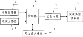
Fig. 2 is the circuit block diagram of the utility model signals collecting and controller part.
Fig. 3 is the structural representation of the utility model metal cabinet.
Fig. 4 is the right view of Fig. 3.
Description of reference numerals:
1-compensation condenser group; The 2-voltage transformer; The 3-current transformer;
The 4-reactor; The 5-AC vacuum contactor; The 6-controller;
The 7-control circuit; The 8-lightning arrester; 9-network communication module;
The 10-metal cabinet; The 11-wall bushing; The 12-fuse switch.
Embodiment
As Fig. 1, shown in Figure 2, the utility model comprises the compensation condenser group 1 that is attempted by on the high pressure electric line, be serially connected in reactor 4 and capacitor switching switch between compensation condenser group 1 and described high pressure electric line respectively, real-time respectively voltage transformer 2 summation current transformers 3 that the voltage and current of described high pressure electric line is sampled, be connected on fuse and lightning arrester 8 on the connection line between compensation condenser group 1 and described high pressure electric line, and according to 3 described capacitor switching switch motions of the corresponding control of detection signal of voltage transformer 2 summation current transformers and tackle controller 6 and the control circuit 7 that each capacitor in the compensation condenser group 1 carries out switching mutually; Described voltage transformer 2 summation current transformers 3 all connect controller 6.In addition, also comprise the network communication module 9 of carrying out the double-direction radio communication with the INTERNET internet, described network communication module and controller 6 join.In the actual use, described network communication module 9 is GPRS wireless data transmission module or other wireless communication module, and is connected in the serial communication mode between described network communication module 9 and the controller 6.
In the present embodiment, described capacitor switching switch is an AC vacuum contactor 5, the monophase current instrument transformer of described current transformer 3 for described high pressure electric line B phase current is sampled, the voltage transformer of voltage transformer 2 for described high pressure electric line AC phase voltage is sampled.Described fuse, reactor 4 and described capacitor switching switch are serially connected on the connection line between each capacitor in described high pressure electric line and the compensation condenser group 1 successively.In addition, described fuse is a fuse switch 12.Described lightning arrester 8 is connected on the connection line between fuse switch 12 and the described capacitor switching switch.
Described controller 6 comprises the A/D sample circuit, the MCU controller that joins with described A/D sample circuit and LCD or the LED display circuit that joins with described MCU controller.Described voltage transformer 2 summation current transformers 3 all connect described A/D sample circuit; that is to say; voltage transformer 2 summation current transformers 3 form signal gathering unit and the two all is sent to controller 6 with its signal of being gathered separately, and also are provided with the photoelectrical coupler that its transmission signals is carried out insulation blocking on voltage transformer 2 summation current transformers 3.In the present embodiment, described MCU controller is a dsp chip, and described dsp chip is TMS320F2812.
In conjunction with Fig. 3, Fig. 4, in the present embodiment, described compensation condenser group 1, voltage transformer 2, reactor 4, described capacitor switching switch summation current transformer 3 are installed in metal cabinet 10 inside.The three phase network cable that joins with described high pressure electric line penetrates in the metal cabinet 10 by wall bushing 11.Described lightning arrester 8 and fuse switch 12 all are positioned at metal cabinet 10 outsides and the two is installed in from the three phase network cable of described high pressure electric line access metal cabinet 10 inside.Described voltage transformer 2 summation current transformers 3 are sampled to the voltage and current of described three phase network cable respectively, and compensation condenser group 1 is attempted by on the described high pressure electric line by described three phase network cable.
The course of work of the present utility model is: at first, will penetrate in the metal cabinet 10 through wall bushing 11 with the three phase network cable that described high pressure electric line joins; Be installed in voltage transformer 2 summation current transformers 3 in the metal cabinet 10, in real time the voltage and current of described high pressure electric line sampled, and institute's sampled signal is sent into controller 6; Draw electrical energy parameters such as reactive power by controller 6 by the inter-process computing again, controller 6 outputs control signals to control circuit 7 simultaneously, comes the switching of control compensation capacitor group 1 by control circuit 7, makes the power factor of three phase network circuit reach requirement; Simultaneously, the reactor 4 of series connection suitable capacity on each capacitor in compensation condenser group 1 is with the inrush phenomenon of inhibition compensation condenser and the harmonic current in the electrical network.To sum up, controller 6 judges according to the real time data that collects three phase network line voltage distribution and electric current, and correspondingly sends rational control command, and the switching of each capacitor in the compensation condenser group 1 is finished in 5 adhesives of control AC vacuum contactor.In addition, owing to be serially connected with the reactor of certain capacitance in the loop in compensation condenser group 1 between each capacitor and described high pressure electric line, inrush phenomenon in the time of can effectively reducing the capacitor input, increased the useful life of equipment, can suppress simultaneously amplification, reduce harmonic pollution electrical network to the line harmonic electric current.In use of the present utility model, 12 pairs of package units of described drop out fuse carry out short-circuit protection, if be short-circuited fault, drop out fuse 12 fuses immediately, prevent that short trouble from working the mischief to device and circuit; Described lightning arrester 8 makes package unit avoid the thunder and lightning infringement.In actual use simultaneously, the double-direction radio communication that realizes between the utility model controller 6 and INTERNET internet by network communication module 9.
The above; it only is preferred embodiment of the present utility model; be not that the utility model is imposed any restrictions; everyly any simple modification that above embodiment did, change and equivalent structure are changed, all still belong in the protection range of technical solutions of the utility model according to the utility model technical spirit.
Claims (10)
1. intelligent High Voltage and Passive Automatic Compensation Device, it is characterized in that: comprise the compensation condenser group (1) that is attempted by on the high pressure electric line, be serially connected in reactor (4) and capacitor switching switch between compensation condenser group (1) and described high pressure electric line respectively, real-time respectively voltage transformer (2) summation current transformer (3) that the voltage and current of described high pressure electric line is sampled, be connected on fuse on the connection line and lightning arrester (8) between compensation condenser group (1) and described high pressure electric line, and according to the described capacitor switching switch motion of the corresponding control of voltage transformer (2) summation current transformer (3) institute's detection signal and tackle controller (6) and the control circuit (7) that each capacitor in the compensation condenser group (1) carries out switching mutually; Described voltage transformer (2) summation current transformer (3) all connects controller (6).
2. according to the described intelligent High Voltage and Passive Automatic Compensation Device of claim 1, it is characterized in that: also comprise the network communication module (9) of carrying out the double-direction radio communication with the INTERNET internet, described network communication module and controller (6) join.
3. according to claim 1 or 2 described intelligent High Voltage and Passive Automatic Compensation Device, it is characterized in that: described controller (6) comprises the A/D sample circuit, the MCU controller that joins with described A/D sample circuit and LCD or the LED display circuit that joins with described MCU controller; Voltage transformer (2) summation current transformer (3) all connects described A/D sample circuit.
4. according to the described intelligent High Voltage and Passive Automatic Compensation Device of claim 3, it is characterized in that: described MCU controller is a dsp chip, and described dsp chip is TMS320F2812.
5. according to claim 1 or 2 described intelligent High Voltage and Passive Automatic Compensation Device, it is characterized in that: described compensation condenser group (1), voltage transformer (2), reactor (4), described capacitor switching switch summation current transformer (3) are installed in metal cabinet (10) inside; The three phase network cable that joins with described high pressure electric line penetrates in the metal cabinet (10) by wall bushing (11), voltage transformer (2) summation current transformer (3) is sampled to the voltage and current of described three phase network cable respectively, and compensation condenser group (1) is attempted by on the described high pressure electric line by described three phase network cable.
6. according to the described intelligent High Voltage and Passive Automatic Compensation Device of claim 2, it is characterized in that: be connected in the serial communication mode between described network communication module (9) and the controller (6).
7. according to claim 2 or 6 described intelligent High Voltage and Passive Automatic Compensation Device, it is characterized in that: described network communication module (9) is the GPRS wireless data transmission module.
8. according to claim 1 or 2 described intelligent High Voltage and Passive Automatic Compensation Device, it is characterized in that: described capacitor switching switch is AC vacuum contactor (5).
9. according to claim 1 or 2 described intelligent High Voltage and Passive Automatic Compensation Device, it is characterized in that: the monophase current instrument transformer of described current transformer (3) for described high pressure electric line B phase current is sampled.
10. according to claim 1 or 2 described intelligent High Voltage and Passive Automatic Compensation Device, it is characterized in that: described fuse is fuse switch (12).
Priority Applications (1)
| Application Number | Priority Date | Filing Date | Title |
|---|---|---|---|
| CNU2009200319562U CN201360149Y (en) | 2009-02-20 | 2009-02-20 | Intelligent type high-voltage wattles automatic compensation device |
Applications Claiming Priority (1)
| Application Number | Priority Date | Filing Date | Title |
|---|---|---|---|
| CNU2009200319562U CN201360149Y (en) | 2009-02-20 | 2009-02-20 | Intelligent type high-voltage wattles automatic compensation device |
Publications (1)
| Publication Number | Publication Date |
|---|---|
| CN201360149Y true CN201360149Y (en) | 2009-12-09 |
Family
ID=41425914
Family Applications (1)
| Application Number | Title | Priority Date | Filing Date |
|---|---|---|---|
| CNU2009200319562U Expired - Fee Related CN201360149Y (en) | 2009-02-20 | 2009-02-20 | Intelligent type high-voltage wattles automatic compensation device |
Country Status (1)
| Country | Link |
|---|---|
| CN (1) | CN201360149Y (en) |
Cited By (6)
| Publication number | Priority date | Publication date | Assignee | Title |
|---|---|---|---|---|
| CN102364803A (en) * | 2011-11-15 | 2012-02-29 | 陈振石 | High-voltage line type intelligent reactive power compensation device |
| CN102904264A (en) * | 2012-09-29 | 2013-01-30 | 浙江紫光电器有限公司 | High-voltage reactive power automatic compensation device |
| CN103595059A (en) * | 2013-10-24 | 2014-02-19 | 国家电网公司 | Reactive compensation device of 10kV line |
| CN104065089A (en) * | 2014-06-30 | 2014-09-24 | 国网浙江省电力公司舟山供电公司 | Method for analyzing power cable compensation scheme using reactors in parallel |
| CN108133825A (en) * | 2017-12-25 | 2018-06-08 | 刘林周 | A kind of high-voltage capacitor |
| CN111952983A (en) * | 2020-08-13 | 2020-11-17 | 辽宁配网智慧能源有限公司 | Reactive energy supply and demand balance control method for Internet +10KV distribution line |
-
2009
- 2009-02-20 CN CNU2009200319562U patent/CN201360149Y/en not_active Expired - Fee Related
Cited By (7)
| Publication number | Priority date | Publication date | Assignee | Title |
|---|---|---|---|---|
| CN102364803A (en) * | 2011-11-15 | 2012-02-29 | 陈振石 | High-voltage line type intelligent reactive power compensation device |
| CN102904264A (en) * | 2012-09-29 | 2013-01-30 | 浙江紫光电器有限公司 | High-voltage reactive power automatic compensation device |
| CN102904264B (en) * | 2012-09-29 | 2015-09-16 | 浙江紫光电器有限公司 | A kind of High Voltage and Passive Automatic Compensation Device |
| CN103595059A (en) * | 2013-10-24 | 2014-02-19 | 国家电网公司 | Reactive compensation device of 10kV line |
| CN104065089A (en) * | 2014-06-30 | 2014-09-24 | 国网浙江省电力公司舟山供电公司 | Method for analyzing power cable compensation scheme using reactors in parallel |
| CN108133825A (en) * | 2017-12-25 | 2018-06-08 | 刘林周 | A kind of high-voltage capacitor |
| CN111952983A (en) * | 2020-08-13 | 2020-11-17 | 辽宁配网智慧能源有限公司 | Reactive energy supply and demand balance control method for Internet +10KV distribution line |
Similar Documents
| Publication | Publication Date | Title |
|---|---|---|
| CN201360149Y (en) | Intelligent type high-voltage wattles automatic compensation device | |
| CN102130462B (en) | Intelligent electrical load unbalance compensation device | |
| CN201663358U (en) | Intelligent energy consumption monitoring type three-phase distribution cabinet | |
| CN201878088U (en) | Automatic voltage regulator of switching voltage regulator (SVR) line | |
| CN201238196Y (en) | Intelligent reactive power compensation and harmonic wave filter circuit | |
| CN201956698U (en) | Intelligent compensating device for power load unbalance | |
| CN201528206U (en) | Harmonic wave suppressed type high voltage dynamic reactive power automatic compensation device | |
| CN201528207U (en) | Dynamic high-voltage reactive-power automatic compensation device | |
| CN203368038U (en) | Novel low voltage station area reactive power compensator | |
| CN202260466U (en) | Low-voltage dynamic reactive power three-phase and single-phase mixed filtering compensation device | |
| CN209267187U (en) | Low pressure dynamic zero transition reactive power compensator | |
| CN201498994U (en) | Intelligent high-voltage pole top reactive power compensation device | |
| CN202930939U (en) | Intelligent type three phase electricity-saving appliance | |
| CN205283139U (en) | Connection in series -parallel integration compensation arrangement | |
| CN207664626U (en) | Dynamic voltage adjusting device of power distribution network | |
| CN202206141U (en) | Submerged arc furnace secondary low pressure fixing and dynamic energy-saving compensation device | |
| CN206332455U (en) | A kind of pole voltage power-less comprehensive compensating device towards urban power distribution network | |
| CN202772588U (en) | Wireless monitoring dynamic reactive compensation switching regulator | |
| CN204668953U (en) | A kind of Intelligent power saving system based on filtering harmonic wave | |
| CN206099351U (en) | High voltage wattless automatic compensation arrangement | |
| CN215185877U (en) | High-temperature detection protection reactive compensation control device | |
| CN203166529U (en) | Local automatic compensation device of intelligent three-phase asynchronous motor | |
| CN203415986U (en) | Disperse reactive compensation system of low voltage power distribution station area based on wireless network | |
| CN209608346U (en) | A kind of low voltage dynamic reactive-power compensation system | |
| CN203301163U (en) | Composite switch of 10-kV no-impact switched multi-group capacitor group |
Legal Events
| Date | Code | Title | Description |
|---|---|---|---|
| C14 | Grant of patent or utility model | ||
| GR01 | Patent grant | ||
| CF01 | Termination of patent right due to non-payment of annual fee | ||
| CF01 | Termination of patent right due to non-payment of annual fee |
Granted publication date: 20091209 Termination date: 20180220 |