CN201304267Y - Sandy water purifier - Google Patents
Sandy water purifier Download PDFInfo
- Publication number
- CN201304267Y CN201304267Y CNU2008201404572U CN200820140457U CN201304267Y CN 201304267 Y CN201304267 Y CN 201304267Y CN U2008201404572 U CNU2008201404572 U CN U2008201404572U CN 200820140457 U CN200820140457 U CN 200820140457U CN 201304267 Y CN201304267 Y CN 201304267Y
- Authority
- CN
- China
- Prior art keywords
- stillpot
- drainage bin
- rotating shaft
- conveying belt
- sheet conveying
- Prior art date
- Legal status (The legal status is an assumption and is not a legal conclusion. Google has not performed a legal analysis and makes no representation as to the accuracy of the status listed.)
- Expired - Fee Related
Links
Images


Abstract
The utility model relates to a sandy water purifier; the upper part of a settling tank is provided with a water inlet pipe; a filter board is arranged below the water inlet pipe; a plurality of steady flow plates are arranged below the filter board; a partition board is arranged below the steady flow plates in an inclining way; a scraper conveyor belt is arranged below the partition board; the side of the settling tank is provided with an overflow plate; a water outlet pipe is arranged outside the overflow plate; the side surface of the settling tank is provided with a lifting tank; the lifting tank is arranged in an inclining way, with the bottom communicated with the settling tank and the inside provided with the scraper conveyor belt, and is connected with the scraper conveyor belt in the settling tank; the upper end of the lifting tank is connected with a dewatering bin; the dewatering bin is a hollow cylinder which is arranged horizontally; a rotating shaft is arranged in the dewatering bin; the rotating shaft is provided with a spiral blade; the top end of the propulsion direction of the spiral blade is provided with a dewatering barrel; dense small holes are distributed on the wall of the dewatering barrel; the outer end of the dewatering bin is provided with a sand outlet, and the bottom is provided with a reflux pipe; the reflux pipe is connected with the settling tank; and the water purifier can quickly settle fine sand in sandy water, dewater and dry, thereby improving the water purifying efficiency and helping the classified utilization of the precipitate.
Description
Technical field
The utility model relates to a kind of water treatment facilities, mainly is to be used for the water treatment facilities that the sewage solid suspension is handled, especially for a kind of husky water purifying machine of troilite tail water processing.
Background technology
Pyrite beneficiation tail water is handled the settling pit desiltings that adopt more at present, and backwater utilizes again, the useless husky dehydration of being exposed to the sun, the labor cleaning's settling pit of adopting.This method method is very fast to the rove solids precipitation, but because the current disturbance that the continuous impact of husky aqueous mixtures produces, make the thinner grains of sand be difficult to effective precipitation, must use more, comparatively broad setting pot, occupation of land is many, and efficient is low, simultaneously, water resource is utilized low again, and the grains of sand thickness of post precipitation is mixed, and is difficult to utilize once more.
The utility model content
The purpose of this utility model provide a kind of by the precipitation and the acting in conjunction of centrifugation realize husky moisture from husky water purifying machine, in order to the husky water that passes through behind the preliminary sedimentation is purified once more.
The purpose of this utility model is achieved in that a kind of husky water purifying machine, comprises stillpot, upgrading slot and drainage bin.Water inlet pipe is arranged at stillpot top, the water inlet pipe below is equipped with filter plate, the filter plate below vertically is equipped with the polylith stabilier, the stabilier below is tiltedly installed with the polylith dividing plate, the dividing plate below is equipped with scrapes sheet conveying belt, the stillpot side is equipped with overflow plate, overflow plate is equipped with outlet pipe outward, in the stillpot side upgrading slot is arranged, the upgrading slot tiltably-mounted, the bottom is communicated with stillpot, inside is equipped with scrapes sheet conveying belt, be connected with the sheet conveying belt of scraping in the stillpot, scraping in the stillpot scraped sheet conveying belt and extra-organismal reducing gear in sheet conveying belt and the upgrading slot, motor is in transmission connection, the upgrading slot upper end connects drainage bin, and drainage bin is the cylinder of interior sky, horizontal setting, inside is equipped with rotating shaft, drainage bin is extended in rotating shaft and motor is in transmission connection, and in the rotating shaft helical blade is arranged, and the diameter of helical blade and drainage bin internal diameter coincide, there is dehydration barrel on helical blade direction of propulsion top, dehydration barrel bucket wall has intensive aperture, and dehydration barrel is installed in drainage bin inside by a plurality of pulleys, but axial rotation, and be in transmission connection with the motor that is installed in the drainage bin outside, there is sand outlet the drainage bin outer end, and return duct is arranged at the bottom, and return duct is connected with stillpot.
As preferably, filter plate adopts mariages peptide net to make.
As preferably, the dividing plate of stillpot inside is multi-layer intercrossed installation.
As preferably, helical blade is flexible materials such as rubber, is installed in the rotating shaft by support, and the use of flexible material helps helical blade and cooperates comparatively closely with the drainage bin inwall.
During use, to handle through preliminary sedimentation, the silt water of removing larger particles enters stillpot by water inlet pipe, through filter plate current are slowed down, and disperse, dirty equably, stabilier can further keep water body stable, reduce the current disturbance, quickening precipitation produces, the grains of sand are in precipitation and slip under the self gravitation effect on the dividing plate, and the sheet conveying belt of scraping bottom stillpot is delivered to upgrading slot, and the sheet conveying belt of scraping in the upgrading slot is promoted to drainage bin with the grains of sand, lifting process drop simultaneously goes out moisture, the grains of sand are promoted by helical blade at drainage bin, enter dehydration barrel, under the extruding acting in conjunction of centrifugal force that dehydration barrel is rotated at a high speed and helical blade, further dehydration, the grains of sand after the dehydration are discharged from sand outlet, and the moisture that dehydration barrel throws away flows back to the stillpot circulation through return duct, and the stillpot upper strata water of cleaning covers overflow plate, flow out from outlet pipe, utilize again.Constantly the silt of precipitation is upwards promoted owing to scrape sheet conveying belt, make the sediment charge of stillpot inside keep reduced levels all the time, reduced the concentration of the inner silt water of stillpot, the generation that helps precipitating.
By enforcement the utility model, but the tiny grains of sand in the rapid precipitation silt water, and dehydrate, improved the water purification efficiency, help sedimentary classified use.
Description of drawings
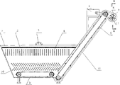
Fig. 1 is a scheme of installation of the present utility model;
Fig. 2 is the utility model vertical view.
Fig. 3 is the left-hand cutaway view of the utility model stillpot.
Fig. 4 is that the A-A of Fig. 1 is to cutaway view.
1 is stillpot among the figure, the 2nd, and filter plate, the 3rd, water inlet pipe, the 4th, stabilier, the 5th, motor, the 6th, drainage bin, the 7th, helical blade, the 8th, scrape sheet conveying belt, the 9th, scrape sheet conveying belt, the 10th, dividing plate, the 11st, rotating shaft, the 12nd, upgrading slot, the 13rd, reducing gear, the 14th, motor, the 15th, outlet pipe, the 16th, motor, the 17th, reducing gear, the 18th, dehydration barrel, the 19th, pulley, the 20th, overflow plate, the 21st, sand outlet, the 22nd, return duct.
The specific embodiment
The utility model is further described by embodiment below in conjunction with accompanying drawing.
The purpose of this utility model is achieved in that a kind of husky water purifying machine, comprises stillpot 1, upgrading slot 12 and drainage bin 6.Water inlet pipe 3 is arranged at stillpot 1 top, water inlet pipe 3 belows are equipped with filter plate 2, filter plate 2 adopts mariages peptide net to make, filter plate 2 belows vertically are equipped with polylith stabilier 4, stabilier 4 belows are tiltedly installed with polylith dividing plate 10, dividing plate 10 is multi-layer intercrossed installation, dividing plate 10 belows are equipped with scrapes sheet conveying belt 9, stillpot 1 side is equipped with overflow plate 20, the overflow plate 20 outer outlet pipes 15 that are equipped with, in stillpot 1 side upgrading slot 12 is arranged, upgrading slot 12 tiltably-mounteds, the bottom is communicated with stillpot 1, upgrading slot 12 inside are equipped with scrapes sheet conveying belt 10, be connected with the sheet conveying belt 9 of scraping in the stillpot 1, scraping in the stillpot 1 scraped sheet conveying belt 10 and extra-organismal reducing gear 13 in sheet conveying belt 9 and the upgrading slot 12, motor 14 is in transmission connection, upgrading slot 12 upper ends connect drainage bin 6, drainage bin 6 is the cylinder of interior sky, horizontal setting, inside is equipped with rotating shaft 11, rotating shaft 11 is extended drainage bin 6 and is in transmission connection with reducing gear 17 and motor 16, helical blade 7 is arranged in the rotating shaft 11, the internal diameter of the diameter of helical blade 7 and drainage bin 6 coincide, helical blade 7 is flexible materials such as rubber, be installed in the rotating shaft 11 by support, the use of flexible material helps helical blade 11 and cooperates comparatively closely with drainage bin 6 inwalls, there is dehydration barrel 18 on helical blade 7 direction of propulsion tops, 18 barrels of walls of dehydration barrel have intensive aperture, dehydration barrel 18 is installed in drainage bin 6 inside by a plurality of pulleys 19, but axial rotation, and be in transmission connection with the motor 5 that is installed in drainage bin 6 outsides, there is sand outlet 21 drainage bin 6 outer ends, return duct 22 is arranged at the bottom, and return duct 22 is connected with stillpot 1.
Claims (3)
1, a kind of husky water purifying machine, it is characterized in that: comprise stillpot (1), upgrading slot (12) and drainage bin (6), water inlet pipe (3) is arranged at stillpot (1) top, water inlet pipe (3) below is equipped with filter plate (2), filter plate (2) below vertically is equipped with polylith stabilier (4), stabilier (4) below is tiltedly installed with polylith dividing plate (10), dividing plate (10) below is equipped with scrapes sheet conveying belt (9), stillpot (1) side is equipped with overflow plate (20), the outer outlet pipe (15) that is equipped with of overflow plate (20), in stillpot (1) side upgrading slot (12) is arranged, upgrading slot (12) tiltably-mounted, the bottom is communicated with stillpot (1), upgrading slot (12) inside is equipped with scrapes sheet conveying belt (10), be connected with the sheet conveying belt (9) of scraping in the stillpot (1), the sheet conveying belt of scraping in sheet conveying belt (9) and the upgrading slot (12) (10) of scraping in the stillpot (1) is in transmission connection with extra-organismal reducing gear (13) and motor (14), upgrading slot (12) upper end connects drainage bin (6), drainage bin (6) is the cylinder of interior sky, horizontal setting, inside is equipped with rotating shaft (11), rotating shaft (11) is extended drainage bin (6) and is in transmission connection with reducing gear (17) and motor (16), helical blade (7) is arranged in the rotating shaft (11), the internal diameter of the diameter of helical blade (7) and drainage bin (6) coincide, there is dehydration barrel (18) on helical blade (7) direction of propulsion top, dehydration barrel (18) bucket wall has intensive aperture, dehydration barrel (18) is installed in drainage bin (6) inside by a plurality of pulleys (19), but axial rotation, and with being installed in drainage bin (6) outside motor (5) is in transmission connection, there is sand outlet (21) drainage bin (6) outer end, return duct (22) is arranged at the bottom, and return duct (22) is connected with stillpot (1).
2, a kind of husky moisture as claimed in claim 1 is disembarked, and it is characterized in that: the inner dividing plate (10) of stillpot (1) is multi-layer intercrossed installation.
3, a kind of husky moisture as claimed in claim 1 or 2 is disembarked, and it is characterized in that: helical blade (7) is installed in the rotating shaft (11) by support for flexible materials such as rubber.
Priority Applications (1)
| Application Number | Priority Date | Filing Date | Title |
|---|---|---|---|
| CNU2008201404572U CN201304267Y (en) | 2008-09-19 | 2008-09-19 | Sandy water purifier |
Applications Claiming Priority (1)
| Application Number | Priority Date | Filing Date | Title |
|---|---|---|---|
| CNU2008201404572U CN201304267Y (en) | 2008-09-19 | 2008-09-19 | Sandy water purifier |
Publications (1)
| Publication Number | Publication Date |
|---|---|
| CN201304267Y true CN201304267Y (en) | 2009-09-09 |
Family
ID=41096729
Family Applications (1)
| Application Number | Title | Priority Date | Filing Date |
|---|---|---|---|
| CNU2008201404572U Expired - Fee Related CN201304267Y (en) | 2008-09-19 | 2008-09-19 | Sandy water purifier |
Country Status (1)
| Country | Link |
|---|---|
| CN (1) | CN201304267Y (en) |
Cited By (6)
| Publication number | Priority date | Publication date | Assignee | Title |
|---|---|---|---|---|
| CN101975169A (en) * | 2010-11-02 | 2011-02-16 | 鸡西市健鑫农业科技开发有限公司 | High-flow underflow pump for biogas generating pit |
| CN105536978A (en) * | 2016-02-22 | 2016-05-04 | 河南建科百合管桩有限公司 | Small-particle aggregate recovery device and scrubbing device provided with recovery device |
| CN111236349A (en) * | 2020-03-09 | 2020-06-05 | 南京清中环境技术有限公司 | Special equipment for cleaning organic debris and sediments on water bottom surface layer |
| CN111408168A (en) * | 2020-05-18 | 2020-07-14 | 张丽 | Sedimentation tank cleaning equipment for sewage treatment |
| CN114988624A (en) * | 2021-12-30 | 2022-09-02 | 武汉市政环境工程建设有限公司 | Method for treating leachate of refuse landfill |
| CN115869665A (en) * | 2022-12-19 | 2023-03-31 | 江苏新天鸿集团有限公司 | Underwater mud scraper for sedimentation tank |
-
2008
- 2008-09-19 CN CNU2008201404572U patent/CN201304267Y/en not_active Expired - Fee Related
Cited By (7)
| Publication number | Priority date | Publication date | Assignee | Title |
|---|---|---|---|---|
| CN101975169A (en) * | 2010-11-02 | 2011-02-16 | 鸡西市健鑫农业科技开发有限公司 | High-flow underflow pump for biogas generating pit |
| CN105536978A (en) * | 2016-02-22 | 2016-05-04 | 河南建科百合管桩有限公司 | Small-particle aggregate recovery device and scrubbing device provided with recovery device |
| CN111236349A (en) * | 2020-03-09 | 2020-06-05 | 南京清中环境技术有限公司 | Special equipment for cleaning organic debris and sediments on water bottom surface layer |
| CN111408168A (en) * | 2020-05-18 | 2020-07-14 | 张丽 | Sedimentation tank cleaning equipment for sewage treatment |
| CN114988624A (en) * | 2021-12-30 | 2022-09-02 | 武汉市政环境工程建设有限公司 | Method for treating leachate of refuse landfill |
| CN115869665A (en) * | 2022-12-19 | 2023-03-31 | 江苏新天鸿集团有限公司 | Underwater mud scraper for sedimentation tank |
| CN115869665B (en) * | 2022-12-19 | 2024-02-13 | 江苏新天鸿集团有限公司 | Sedimentation tank is mud scraper under water |
Similar Documents
| Publication | Publication Date | Title |
|---|---|---|
| CN201305491Y (en) | Water purifier | |
| CN201304267Y (en) | Sandy water purifier | |
| CN101921050B (en) | Device and method for dewatering and drying mud under water | |
| CN206069590U (en) | Rainwater high efficiency clarification tank | |
| CN1642862A (en) | Method and device for clarification of liquids, particularly water, loaded with material in suspension | |
| CN103880131B (en) | A kind of method and apparatus of micro-vortex efficient clarifying reaction device | |
| CN104230123B (en) | Remove the device of inorganic particle in Sewage treatment systems | |
| CN203653357U (en) | Air floater integrating cant board oil separation, cavitation and dissolved air floatation devices | |
| CN110683722B (en) | Waste water purification treatment device and treatment process for plastic granulation | |
| CN105879464A (en) | Municipal sewage sand removing device and method | |
| CN112830561A (en) | Sand setting and precipitating device and method | |
| CN204502490U (en) | A kind of high-efficiency coagulative precipitation tank | |
| CN111359272B (en) | Cleaning device for residual water pond sediment mud | |
| CN206955726U (en) | A kind of separator for mud and water | |
| CN103086471A (en) | Flocculent precipitate oil remover capable of heating and backflushing automatically | |
| CN202089878U (en) | Sludge concentrator | |
| Shammas et al. | Sedimentation | |
| CN201305476Y (en) | Sand-water separator | |
| KR101869471B1 (en) | A treatment device that sinks sand mixed with sewage-like wastewater | |
| CN101376545B (en) | Water purification apparatus | |
| CN102583674B (en) | Integrated oily mud wastewater pipe bundle coagulation and separation reactor | |
| CN214457072U (en) | Sand setting and precipitating device | |
| CN214781431U (en) | Slurry concentration equipment | |
| CN215275892U (en) | Water treatment sedimentation tank | |
| KR870001854A (en) | Method and apparatus for separating solid from liquid |
Legal Events
| Date | Code | Title | Description |
|---|---|---|---|
| C14 | Grant of patent or utility model | ||
| GR01 | Patent grant | ||
| CF01 | Termination of patent right due to non-payment of annual fee |
Granted publication date: 20090909 Termination date: 20140919 |
|
| EXPY | Termination of patent right or utility model |