CN201258071Y - Bicycle manual booster body building apparatus - Google Patents
Bicycle manual booster body building apparatus Download PDFInfo
- Publication number
- CN201258071Y CN201258071Y CNU2008200723227U CN200820072322U CN201258071Y CN 201258071 Y CN201258071 Y CN 201258071Y CN U2008200723227 U CNU2008200723227 U CN U2008200723227U CN 200820072322 U CN200820072322 U CN 200820072322U CN 201258071 Y CN201258071 Y CN 201258071Y
- Authority
- CN
- China
- Prior art keywords
- bicycle
- support
- shaft
- bearing
- hinged
- Prior art date
- Legal status (The legal status is an assumption and is not a legal conclusion. Google has not performed a legal analysis and makes no representation as to the accuracy of the status listed.)
- Expired - Fee Related
Links
Images


Landscapes
- Steering Devices For Bicycles And Motorcycles (AREA)
Abstract
The utility model relates to a manual power-assisted fitness device of a bicycle. The fitness device is characterized in that the fitness device comprises a handlebar; the lower end thereof is fixedly connected with a beam and a rotating sleeve; the rotating sleeve is sleeved on a fixed shaft of a support; the support is fixedly connected with a front fork; a support arm is fixedly connected on the beam; the front end of the support arm is hinged with the upper end of a connecting rod; the lower end of the connecting rod is hinged with a crankshaft; the crankshaft is fixedly connected with an one-way rotating cam; a rotating shaft is arranged in a fixed sleeve of the support; the one-way rotating cam and a drive sprocket are fixedly arranged at two ends of the rotating shaft; a positioning pressing arm is arranged on a spring support shaft arranged on the support; a pressing spring is sleeved on the spring support shaft; a pressing rolling wheel which is hinged at the front end of the positioning pressing arm is contacted with a flange of the one-way rotating cam; and the drive sprocket fixedly arranged at the rotating shaft is connected with a flywheel arranged on a front shaft of the bicycle through a chain. The fitness device has the advantages of simple structure, good power-assisted effect, ability of being conductive to climbing, better fitness effect, etc.
Description
Technical field
The utility model relates to bicycle, three-wheel vehicle and being connected, and has the manual power-assisted fitness equipment of bicycle of power-assisted, body building function.
Background technology
Existing pedal type bicycle, three-wheel vehicle promptly are the vehicle of riding instead of walk, are the physical fitness utensils again, but a kind of power-assisted of riding is not arranged so far as yet, be convenient to climbing, body-building effect is better, be contained in the power-assisted fitness equipment on bicycle, the three-wheel vehicle, also do not see the report of the manual power-assisted fitness equipment of bicycle.
Summary of the invention
It is a kind of simple in structure that the purpose of this utility model is to provide, and power-assisted is effective, the manual power-assisted fitness equipment of bicycle that body-building effect is better.
The purpose of this utility model is achieved through the following technical solutions: the manual power-assisted fitness equipment of a kind of bicycle, its characteristics are: it comprises that the lower end of handlebar and crossbeam and turning set are connected, turning set is contained on the anchor shaft of bearing, bearing and front vehicle fork are connected, be fixed with support arm on the crossbeam, the front end and the small end of support arm are hinged, the lower end and the bent axle of connecting rod are hinged, bent axle and unidirectional rotation cam are connected, in the fixed cover of bearing, turning cylinder is housed, unidirectional rotation cam and drive sprocket are packed in the two ends of turning cylinder, on the spring pivot shaft of putting on the bearing, the location clamping arm is housed, be nested with holddown spring on the spring pivot shaft, location clamping arm front end pivotally attached pinch rollers contacts with the flange of unidirectional rotation cam, and the drive sprocket that turning cylinder installs is connected with the flywheel of installing on the bicycle front axle by chain.
The manual power-assisted fitness equipment of bicycle of the present utility model, owing to adopt the support arm of handlebar by being connected with it, with support arm pivotally attached connecting rod, bent axle with rod hinge connection, the unidirectional rotation cam that is connected with bent axle, unidirectional rotation cam and drive sprocket are packed in the two ends of turning cylinder, location clamping arm front end pivotally attached pinch rollers is pressed the flange of unidirectional rotation cam all the time under the effect of holddown spring, the drive sprocket that turning cylinder installs is by chain and the flywheel bonded assembly structure of installing on the bicycle front axle, before garage, the rear to push-and-pull vehicle reciprocating, all can drive to move ahead and realize the purpose of power-assisted and body-building, have simple in structure, power-assisted is effective, be beneficial to climbing, advantage such as body-building effect is better.
Description of drawings
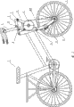
Fig. 1 is that the manual power-assisted fitness equipment of bicycle is installed in the structural representation on the bicycle.
Fig. 2 is the schematic rear view of Fig. 1.
Fig. 3 looks scheme drawing (I partial enlarged drawing among Fig. 1) for the manual power-assisted body-building equipment structure of bicycle master.
Fig. 4 looks scheme drawing for the left side of Fig. 3.
Fig. 5 is the manual power-assisted fitness equipment of the bicycle view that travels forward.
Among the figure: 1 bicycle, 2 handlebars, 3 support arms, 4 connecting rods, 5 drive sprockets, 6 chains, 7 flywheels, 8 turning sets, 9 location clamping arms, 10 unidirectional rotation cams, 11 guiding tension wheels, 12 crossbeams, 13 pinch rollers, 14 holddown springs, 15 position-limited levers, 16 bearings, 17 turning cylinders, 18 fixed covers, 19 anchor shafts, 20 front vehicle forks, 21 bent axles, 22 spring pivot shafts.
The specific embodiment
The utility model is described in further detail to utilize drawings and Examples below.
With reference to Fig. 1~4, the manual power-assisted fitness equipment of bicycle of the present utility model is connected with existing bicycle 1, also can be connected with three-wheel vehicle.The manual power-assisted fitness equipment of bicycle is that the lower end of handlebar 2 and crossbeam 12 and turning set 8 are connected, and turning set 8 is contained on the anchor shaft 19 of bearing 16, and bearing 16 is connected with front vehicle fork 20.Be fixed with support arm 3 on the crossbeam 12, the front end of support arm 3 and connecting rod 4 upper ends are hinged, and the lower end of connecting rod 4 and bent axle 21 are hinged, and bent axle 21 is connected with unidirectional rotation cam 10.In the fixed cover 18 of bearing 16 turning cylinder 17 is housed, unidirectional rotation cam 10 and drive sprocket 5 are packed in the two ends of turning cylinder 17.Location clamping arm 9 is housed on the spring pivot shaft of putting on the bearing 16 22, is nested with holddown spring 14 on spring pivot shaft 22, an end of holddown spring 14 contacts with bearing 16, and the other end of holddown spring 14 hangs on the position-limited lever 15 that is provided with on the clamping arm 9 of location.Location clamping arm 9 front end pivotally attached pinch rollers 13 contact with the flange of unidirectional rotation cam 10.The drive sprocket 5 that turning cylinder 17 installs is connected with the flywheel of installing on the bicycle front axle 7 by chain 6.The guiding tension wheel 11 that is provided with on front vehicle fork 20 is used to adjust tension chain 6.
With reference to Fig. 1 and 5, when using the manual power-assisted fitness equipment of bicycle of the present utility model, holding handlebar 2 pushes away forward, handlebar 2 makes the turning set 8 that is connected with handlebar 2 rotate counterclockwise around anchor shaft 19, the crossbeam 12 that handlebar 2 is connected deflects down the support arm 3 that is connected on the crossbeam 12, support arm 3 pivotally attached connecting rods 4 drive bent axle 21 and rotate, the unidirectional rotation cam 10 that bent axle 21 is connected rotates counterclockwise, unidirectional rotation cam 10 and drive sprocket 5 are packed in the two ends of turning cylinder 17, make drive sprocket 5 drive by chain 6 that the flywheel of installing 7 rotates on the bicycle front axle and the auxiliary power driven vehicle wheel moves ahead; Make handlebar 2 by preceding pulling back again, handlebar 2 makes the turning set 8 that is connected with handlebar 2 clockwise rotate around anchor shaft 19, the crossbeam 12 that handlebar 2 is connected upward deflects the support arm 3 that is connected on the crossbeam 12, but the flange that under the effect of holddown spring 14, presses unidirectional rotation cam 10 because of location clamping arm 9 front end pivotally attached pinch rollers 13 all the time, force unidirectional rotation cam 10 to continue to rotate counterclockwise, make drive sprocket 5 drive by chain 6 that the flywheel of installing 7 rotates on the bicycle front axle and the auxiliary power driven vehicle wheel moves ahead, back and forth before, back push-and-pull vehicle realizes that continuous auxiliary power driven vehicle wheel moves ahead to 2.Hold in the process of handlebar 2 reciprocal forward and backward push-and-pulls, human body seesaws, and the arm song is stretched motion, therefore, not only can make the car power-assisted, can also promote the dynamics of human motion, makes body-building effect better.Because the manual power-assisted fitness equipment of bicycle is connected by bearing 16 and front vehicle fork 20, so that bicycle turns to is identical with existing bicycle, three-wheel vehicle.
Claims (1)
1. manual power-assisted fitness equipment of bicycle, it is characterized in that: it comprises that the lower end of handlebar and crossbeam and turning set are connected, turning set is contained on the anchor shaft of bearing, bearing and front vehicle fork are connected, be fixed with support arm on the crossbeam, the front end and the small end of support arm are hinged, the lower end and the bent axle of connecting rod are hinged, bent axle and unidirectional rotation cam are connected, in the fixed cover of bearing, turning cylinder is housed, unidirectional rotation cam and drive sprocket are packed in the two ends of turning cylinder, on the spring pivot shaft of putting on the bearing, the location clamping arm is housed, be nested with holddown spring on the spring pivot shaft, location clamping arm front end pivotally attached pinch rollers contacts with the flange of unidirectional rotation cam, and the drive sprocket that turning cylinder installs is connected with the flywheel of installing on the bicycle front axle by chain.
Priority Applications (1)
| Application Number | Priority Date | Filing Date | Title |
|---|---|---|---|
| CNU2008200723227U CN201258071Y (en) | 2008-08-22 | 2008-08-22 | Bicycle manual booster body building apparatus |
Applications Claiming Priority (1)
| Application Number | Priority Date | Filing Date | Title |
|---|---|---|---|
| CNU2008200723227U CN201258071Y (en) | 2008-08-22 | 2008-08-22 | Bicycle manual booster body building apparatus |
Publications (1)
| Publication Number | Publication Date |
|---|---|
| CN201258071Y true CN201258071Y (en) | 2009-06-17 |
Family
ID=40772303
Family Applications (1)
| Application Number | Title | Priority Date | Filing Date |
|---|---|---|---|
| CNU2008200723227U Expired - Fee Related CN201258071Y (en) | 2008-08-22 | 2008-08-22 | Bicycle manual booster body building apparatus |
Country Status (1)
| Country | Link |
|---|---|
| CN (1) | CN201258071Y (en) |
Cited By (2)
| Publication number | Priority date | Publication date | Assignee | Title |
|---|---|---|---|---|
| CN102328721A (en) * | 2011-07-12 | 2012-01-25 | 上海大学 | Hand-driven hand-controlled walk-substituting device |
| CN108820110A (en) * | 2018-08-20 | 2018-11-16 | 张海松 | A kind of Exercycle |
-
2008
- 2008-08-22 CN CNU2008200723227U patent/CN201258071Y/en not_active Expired - Fee Related
Cited By (2)
| Publication number | Priority date | Publication date | Assignee | Title |
|---|---|---|---|---|
| CN102328721A (en) * | 2011-07-12 | 2012-01-25 | 上海大学 | Hand-driven hand-controlled walk-substituting device |
| CN108820110A (en) * | 2018-08-20 | 2018-11-16 | 张海松 | A kind of Exercycle |
Similar Documents
| Publication | Publication Date | Title |
|---|---|---|
| CN201258071Y (en) | Bicycle manual booster body building apparatus | |
| CN202896803U (en) | Double-pedal three-roller scooter | |
| CN202130548U (en) | Four-rod driving bicycle | |
| CN201685956U (en) | Linear-pedaling bicycle | |
| CN201179947Y (en) | Manpower mechanism | |
| CN102935871A (en) | Bicycle capable of being driven by hand | |
| CN203047484U (en) | Sport recreational vehicle | |
| CN201721583U (en) | Bicycle | |
| CN201049695Y (en) | Compression spring type assisted bicycle | |
| CN202107051U (en) | Mini-type scooter driven by man | |
| WO2010056010A3 (en) | Double driving apparatus for a bicycle | |
| CN201566771U (en) | Upper-lower foot pedal driven scooter | |
| CN201209014Y (en) | Double-movable chain wheel driving three-wheel stand-riding vehicle | |
| CN201501501U (en) | Labor-saving high-speed bicycle | |
| CN201264704Y (en) | Double-action chain sprocket drive type two-wheeled stand-riding vehicle | |
| CN104015862A (en) | Chain reciprocating transmission type pedal bicycle | |
| CN204871403U (en) | Portable folding bicycle | |
| CN201161688Y (en) | Pedal lever driven bicycle | |
| CN217554092U (en) | Arm force driven tricycle | |
| CN2652784Y (en) | Pedal rod type power saving bicycle | |
| CN218594496U (en) | Pedal ground type bicycle | |
| JP5382834B1 (en) | Arm stepped bicycle | |
| CN201296347Y (en) | Power transmission device used on jinrikisha, bicycle and scooter | |
| CN204056172U (en) | A kind of pedal gear be applied in bicycle | |
| CN201296321Y (en) | Foot-operated and labor-saving bicycle |
Legal Events
| Date | Code | Title | Description |
|---|---|---|---|
| C14 | Grant of patent or utility model | ||
| GR01 | Patent grant | ||
| C17 | Cessation of patent right | ||
| CF01 | Termination of patent right due to non-payment of annual fee |
Granted publication date: 20090617 Termination date: 20110822 |