CN201230200Y - Protection circuit for limiting working power of electrical appliance - Google Patents
Protection circuit for limiting working power of electrical appliance Download PDFInfo
- Publication number
- CN201230200Y CN201230200Y CNU2008201255489U CN200820125548U CN201230200Y CN 201230200 Y CN201230200 Y CN 201230200Y CN U2008201255489 U CNU2008201255489 U CN U2008201255489U CN 200820125548 U CN200820125548 U CN 200820125548U CN 201230200 Y CN201230200 Y CN 201230200Y
- Authority
- CN
- China
- Prior art keywords
- power
- protective circuit
- electric equipment
- resistor
- described electric
- Prior art date
- Legal status (The legal status is an assumption and is not a legal conclusion. Google has not performed a legal analysis and makes no representation as to the accuracy of the status listed.)
- Expired - Lifetime
Links
Images


Classifications
-
- H—ELECTRICITY
- H02—GENERATION; CONVERSION OR DISTRIBUTION OF ELECTRIC POWER
- H02H—EMERGENCY PROTECTIVE CIRCUIT ARRANGEMENTS
- H02H9/00—Emergency protective circuit arrangements for limiting excess current or voltage without disconnection
- H02H9/02—Emergency protective circuit arrangements for limiting excess current or voltage without disconnection responsive to excess current
Abstract
The utility model discloses a protection circuit which limits the operating power of an electrical device in a circuit connected with a power supply under a predetermined rated power. The protection circuit comprises a switch, a sensor, and a comparator, wherein, the switch is connected with the electrical device and adjusts the electric power supplied from the power supply to the electrical device; the sensor senses the parameters relative to the operating power of the electrical device; and the comparator compares the parameters sensed by the sensor to determine undesirable working condition; under the undesirable working condition, the electrical device works with the power exceeding the predetermined rated power. Responding to the undesirable working condition, the comparator provides an output signal in order to control the switch to adjust the electric power supplied to the electrical device under the predetermined rated power; at the same time, current is kept passing through the electrical device.
Description
Technical field
The utility model relates to the protective circuit of the operating power that limits electric equipment, particularly but not relate to lighting apparatus uniquely.
Background technology
In order to protect environment, worldwide, people become more and more careful and have admitted minimize use to fossil fuel substantially, particularly, and to use from the electric power of trunk/domestic power supply.
Illumination is the field that can be realized energy saving by the general public easily.For example, for the general illumination purposes of not making excessive demands illumination intensity usually, recommend the bulb of low relatively rated power.In some jurisdiction of courts field (jurisdiction), the work with lighting apparatus etc. of having formulated constrains in the regulation below the specific wattage rating, for example constrains in below the 109W for the illuminace component on the ceiling fan (light kit).
Yet because carelessness or carefree (lightheartedness), some may still use overpowering bulb for bright illumination more, and this will cause the unnecessary waste of energy and may be dangerous.
The utility model will be by providing a kind of new or improved protective circuit that limits the operating power of electric equipment, eliminates or alleviate such problem or shortcoming at least.
Summary of the invention
According to the utility model, provide a kind of operating power of the electric equipment that will be connected to be limited in protective circuit below the predetermined rated power with power supply, this protective circuit comprises:
The switchgear that is connected with electric equipment is adjusted the electrical power that is supplied to electric equipment from power supply;
Inductor is responded to the parameter relevant with the operating power of electric equipment; And
Comparator, relatively the parameter of inductor induction is with definite working condition of not expecting, and electric equipment carries out work with the power that surpasses predetermined rated power under described working condition; And in response to definite such working condition of not expecting, the electrical power that provides output signal will supply electric equipment with control switch equipment is adjusted to below the predetermined rated power, simultaneously the holding current electric equipment of flowing through.
Preferably, inductor comprises: voltage induced equipment, respond to the operating voltage of described electric equipment, and this operating voltage is described parameter.
More preferably, voltage induced equipment comprises: be connected in series in first resistor between described electric equipment and the described power supply, this first resistor has the terminal of the operating voltage of a described electric equipment of induction in the electric equipment side.
Further more preferably, comparator comprises voltage comparator, and this voltage comparator has: first input end, and the terminal that is connected to first resistor by second resistor is to import the operating voltage of described electric equipment; And second input, be connected with another terminal at first resistor of mains side with input as a comparison reference and appear at the voltage of the another terminal of first resistor.
Further more preferably, the another terminal of first resistor directly is connected with described power supply, makes with described power source voltage as a reference.
Preferably, inductor comprises induction by current equipment, and induction by current equipment has the resistor that is connected in series between described electric equipment and the described power supply to respond to the operating current of described electric equipment, and this operating current is described parameter.
Further preferably, comparator comprises voltage comparator, voltage comparator has respectively two inputs that connect with the relative terminal of resistor, by the electrical potential difference that is relatively produced on resistor by described operating current, determines the described working condition of not expecting.
In a preferred embodiment, switchgear comprises relay, relay is arranged as switching between at least two first and second circuit, first circuit normally is connected to described power supply with described electric equipment, and second circuit is connected to described power supply with described electric equipment after determining the described situation of not expecting.
More preferably, first circuit has low relatively resistance, so that described electric equipment normally is connected to described power supply, second circuit has high relatively resistance, after determining the described situation of not expecting, described electric equipment being connected to described power supply, thereby will be supplied to the electrical power of described electric equipment to be decreased to below the predetermined rated power.
More preferably, switchgear comprises the solid-state switch that described electric equipment is connected to described power supply, this solid-state switch has control terminal, and this control terminal can be switched by the relay between first and second circuit of different resistance, with the duty ratio of the conducting of control solid-state switch.
Further more preferably, solid-state switch comprises triac, by the capacitor that is charged by one of first and second circuit that relay switched to the control terminal of triac is controlled.
More preferably, protective circuit comprises the latch units that is connected between comparator and the relay, the output signal of described comparator is latching to relay makes that relay will keep activating.
More preferably, relay comprises electromagnetic relay, and described electromagnetic relay has the electromagnet of switch and console switch.
In a preferred embodiment, switchgear comprises: described electric equipment is connected to the solid-state switch of described power supply, and this solid-state switch has control terminal; And the trigger element that is connected with control terminal, described output signal in response to comparator provides a series of time control triggering signals to make the solid-state switch conducting at progressive difference starting angle place, thereby the duty ratio of conducting of control solid-state switch, wherein each starting angle is at preset time on the cycle.
More preferably, protective circuit comprises the controller that is connected between comparator and the trigger element, and the timing and the starting angle of the triggering signal of trigger element are controlled.
Further more preferably, controller comprises: counter, provide a series of control signals at interval with described preset time, and control with the timing of triggering signal that trigger element is provided.
Further more preferably, trigger element comprises: capacitor and a plurality of resistive path that are connected with the control terminal of solid-state switch, the starting angle of different resistance with the charging interval of adjusting capacitor progressively and the triggering signal that in turn provided by trigger element is provided each resistive path, alternately activates resistive path by each control signal of counter.
Further more preferably, counter has a plurality of outputs of each control signal of output, and each resistive path comprises resistor and solid-state switch, and this solid-state switch has the activation control terminal that is connected with each output of counter.
Further more preferably, controller comprises the timer that is connected with trigger element, in response to each control signal that is provided by counter the starting angle of the triggering signal of trigger element is adjusted progressively.
Further more preferably, counter has at least one output that is connected with timer that a series of control signals is exported to timer, and control signal is a binary signal.
Preferably, switchgear is sent to described electric equipment with electrical power from described power supply with maximum power at first, subsequently described electrical power is decreased to below the predetermined rated power.
Preferably, controller operationally increases the starting angle of the triggering signal of trigger element, with the duty ratio of the conducting that reduces solid-state switch, makes described electrical power is decreased to below the predetermined rated power.
Preferably, controller operationally reduces the starting angle of triggering signal of trigger element with the duty ratio of the conducting that increases solid-state switch, make and increase described electrical power, surpass predetermined rated power up to it, increase the starting angle of the triggering signal of trigger element subsequently, with the duty ratio of the conducting that reduces solid-state switch, make described electrical power is decreased to below the predetermined rated power.
Preferably, Yu Ding rated power is 190 watts.
Description of drawings
Now will be by only more specifically describing the utility model with reference to the accompanying drawings, in the accompanying drawings in the mode of example:
Fig. 1 is the end perspective view that comprises the electric ceiling of the illuminace component of having incorporated protective circuit into according to of the present utility model;
Fig. 2 is the top perspective view of the ceiling fan of Fig. 1, shows the protective circuit that is contained in the casing that is arranged in ceiling fan installation shaft upper end;
Fig. 3 is the perspective view of amplification of upper end of the installation shaft of Fig. 2, clearly show that casing;
Fig. 4 is the perspective view that opens wide of the casing of Fig. 3, has disclosed protective circuit inside;
Fig. 5 is the schematic circuit of first embodiment of the protective circuit of Fig. 4;
Fig. 6 is the schematic circuit of second embodiment of the protective circuit of Fig. 4;
Fig. 7 is the flow chart of the course of work of having demonstrated the protective circuit of Fig. 5 and 6;
Fig. 8 is the schematic circuit of the 3rd embodiment of the protective circuit of Fig. 4;
Fig. 9 is the flow chart of the course of work of having demonstrated the protective circuit of Fig. 8;
Figure 10 is the schematic circuit of the 4th embodiment of the protective circuit of Fig. 4;
Figure 11 is the flow chart of the course of work of having demonstrated the protective circuit of Figure 10;
Figure 12 is the schematic circuit of the 5th embodiment of the protective circuit of Fig. 4;
Figure 13 is the flow chart of the course of work of having demonstrated the protective circuit of Figure 12;
Figure 14 is the schematic circuit of the 6th embodiment of the protective circuit of Fig. 4;
Figure 15 is the flow chart of the course of work of having demonstrated the protective circuit of Figure 14;
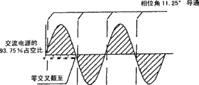
Figure 16 A is to locate the oscillogram of the operating voltage of illuminace component in the duty ratio that reduces gradually that phase control produced (duty cycle) that the protective circuit by Fig. 4 realizes to 16N; And
Figure 17 and 18 shows the duty ratio and therefore and the form of the relation between the power that consumes of the operating voltage of illuminace component.
Embodiment
Fig. 1 to Fig. 5 at first with reference to the accompanying drawings and Fig. 7 show electric equipment, have just incorporated the electric ceiling 10 that embodies protective circuit 100 of the present utility model into.Ceiling fan 10 has typical structure, this typical structure comprises: utilize vertical installation shaft 12 to be hung in motor casing 11 on the ceiling, in shell 11 and drive the fan motor 13 of the fan blade 15 of four or five levels, and be installed in the switch cup (switch cup) 14 below the motor 13.
The ceiling fan 10 of the type of paying close attention to is included in the illuminace component L to room interpolation surround lighting (ambientlight) of its bottom, and it is installed on the switch cup 14.As generally known in the art, utilize (for example) four lamp sockets 4 of fixing each incandescent lamp bulb 5 to form illuminace component L.The ON/OFF switch (not shown) of a pair of cable 2 by the opening/closing illuminace component L on said protective circuit 100 and the switch cup 14 is connected to trunk with lamp socket 4 and exchanges (AC) power supply M.
For environmental protection or security reason or in order to satisfy some security regulations, for illuminace component L just all bulbs 5 have the restriction on rated power or the work wattage together, this is the overload restriction that observe.For example, the wattage restriction is: as the 190W that relevant authorities set, this trunk voltage for 115V (110-120V) is converted into the maximum load current of about 1.65A.In order to satisfy this regulation, the 40W of standard can be used as bulb 5.
Because carelessness or random violating the rules, the bulb of the wattage (for example, each 60W or even 100W) that some may overuse for bright illumination more.This not only violate the rules and also dangerous really.Protective circuit 100 automatically with the work limit of illuminace component L below aforesaid 190W wattage rating.
In the circuit diagram of Fig. 5; as from trunk power supply M to illuminace component L, protective circuit 100 comprises direct current (DC) power subsystem 110, load voltage sampling unit 120, voltage comparator 130, signal latch unit 140 and dimmer (light dimmer) 150.
Be connected in series in very little, the resistor R 1 (for example 0.04 Ω) of monitoring load current as induction by current equipment between trunk power supply live end and the load (illuminace component L just) by use, and resistor R 2 and variable resistance R3 that the series connection of sampling load voltage is provided, 120 pairs of load voltages of load voltage sample circuit are sampled.Electrical potential difference on the resistor R 1 depends on the load current of the groundwork power of reflection illuminace component L.
The load voltage of zero (or near zero) illuminace component L of load current place is actually trunk voltage, therefore this trunk voltage is used as reference voltage.By working voltage comparator 130 load voltage of sampling is compared with trunk voltage (reference voltage just), can determine or the load state (operating power just) of monitoring, illumination parts L.
By adjusting variable resistance R3 voltage comparator 130 is regulated, make voltage comparator 130 on the load current that surpasses the 1.65A restriction (just illuminace component carries out work with the power more than the 190W restriction), to provide high output signal (for example to rise to logic high at once from logic low, rising edge as pulse signal), as long as such situation occurs.This is the situation of not expecting, bulb 5 absorbs (draw) excessive load current (because its excessive wattage) under this situation, thereby makes dimmer 150 tripping operations to alleviate possible danger.
Concrete consideration current sensing resistor R1, described resistor R 1 relative two ends are connected respectively to two inputs of voltage comparator 230, comparator 230 utilizes the electrical potential difference at load current comparison resistance device R1 two ends thus, with the overpower working condition of monitoring and determining not expect as the electric current of the parameter of being considered by reference.
Utilize relay 151 and resistor R 4 to realize dimmer 150.Relay 151 is electromagnetic types, although it can be a solid-state version.It has SPDT (single-pole double throw) switch 152, and in the alive circuit between load voltage sampling unit 120 and illuminace component L, this SPDT switch 152 is connected in series with the resistor R 4 of crossing over two circuit node N1 and N2.By electromagnet 153 console switchs 152 of relay 150, console switch 152, inserts resistor R 4 in the described circuit at trip position the short circuit between illuminace component L and the trunk power supply M in the normal position.
Compare with the normal condition of switch 152, at the trip position of switch 152, the resistor R 4 that is connected in series has greatly limited the electric current by illuminace component L, so bulb 5 only can be with the power grade operation that greatly reduces below the 190W.
In case the output signal of comparator occurs; signal latch unit 140 just latchs and keeps described output signal; and this has guaranteed in a single day relay 151 tripping operation (even after greatly having reduced load current) relays 151 will be kept activating, and dimmer 150 and after this whole protective circuit 100 will keep tripping operation.
Should carry out user action then, just utilize lower powered bulb to replace bulb 5, then illuminace component L be connect electricity again, so protective circuit 100 will reset and allow the operate as normal of the following illuminace component L of 190W then.
The flow chart of Fig. 7 has been summarized the course of work described above.From (step 101), connect the electricity after 0.5s in (for incandescent load inrush current (inrush current) long enough, usually in about 0.3s), voltage comparator 130 determines that whether bulb 5 is with the power work (step 102) more than the 190W.If not, then do not require the illumination intensity of yet not carrying out the control of bulb 5 and bulb 5 remain unchanged (step 103).
Surpass under the situation of 190W at operating power, the high output signal " ON " (step 104) that signal latch unit 140 keeps from voltage comparator 130, dimmer 150 is charged into the operating voltage of (kickin) and restriction illuminace component L then, has therefore reduced the intensity (step 105) of bulb 5.
Dimmer 150 is operated according to resistance.For fear of the excessive rising of the temperature of resistor R 4, its resistance enough big (for example 100k Ω) to such an extent as to fully limit load current.In the present embodiment, especially in the environment that is not too dark, to such an extent as to still but will launch the light that only can note in operation even load current will be reduced to low like this grade bulb 5.
It should be noted that end, will not close or disconnect bulb 5 and also not plan and it be closed or disconnect in the course of work of protective circuit 100.For example, for the illumination indication (light indication) that provides protective circuit 100 to trip or the rated power of bulb 5 is too high, with the little non-zero current of the bulb 5 that keeps flowing through.
This situation is not desirable, this be because, present at bulb 5 that illuminace component L can seem fault (promptly at all not working) under non-luminous trip condition, only be unsuitable for using even truth is them, just cross high power.
Second protective circuit 200 that embodies Fig. 6 of the present utility model does not have such shortcoming.This protective circuit 200 has and the similar circuit design and the course of work of first protective circuit 100, except the reference marker that comprises the letter that keeps identical, represents most equivalent elements by the same reference numbers that has improved 100.
Unique main distinction is dimmer 250, and dimmer 250 carries out work according to AC power waveform rather than ohmically phase control.Except relay 251 and resistor R 4 (4.7k Ω), dimmer 250 comprises: another resistor R 5 (190k Ω), triac (triac) 254, two-terminal switch element (diac) 255 and capacitor C1.Triac 254 and two-terminal switch element 255 all are solid switch equipments.
Utilize the COM terminal of the switch 252 of relay 251 that described switch 252 is connected to circuit node N1, utilize the L1 of switch 252 and L2 terminal respectively by two resistor R 4 and R5 and by capacitor C1 switch 252 is connected to another circuit node N2 subsequently.Cross over circuit node N1 and be connected triac 254 with N2, wherein the gate electrode (control terminal just) of triac 254 is connected to circuit node N2 by two-terminal switch element 255 and capacitor C1.
Two-terminal switch element 255 according to the voltage of crossing over capacitor C1 will be just/negative triggering pulse is applied to the gate electrode of triac 254.In operation, and the half cycle of AC voltage is synchronously and between the half period of each AC voltage, will be repeatedly to capacitor C1 (the applying just described/negative triggering pulse) gate electrode of triac 254 (promptly by) discharge then of charging.
According to the switching position of relay 251, capacitor C1 charges by among resistor R 4 and the R5 any one.Two-terminal switch element 255 is with conducting, trigger or start pulse after condenser voltage surpasses the puncture voltage of two-terminal switch element, to apply, thus triac 254 conductings with the load current conducting to illuminace component L, finish up to the relevant half cycle of AC power.
Should be understood that for simply, can use the triac replacement triac 254 and the two-terminal switch element 255 that have built-in two-terminal switch element at its grid.
If bulb 5 is overpowering and consume surpasses the power of predetermined 190W restriction together, then this will be detected immediately by voltage comparator 230 (according to the data from the sampling of load voltage sampling unit 220).Then, voltage comparator 230 will produce output signal (being kept by signal latch unit 240) for dimmer 250.After having triggered dimmer 250, relay switch 252 changes to the position of tripping operation, thereby replace resistor R 4 capacitor C1 is cut or be connected to resistor R 5.
Because resistor R 5 is sizable resistance (190k Ω), so capacitor C1 will spend the puncture voltage that considerable time charges to two-terminal switch element 255.This causes triac 254 to begin to have the conducting of delay from the starting point of each half cycle, thus triac 254 only on the part-time in each half cycle (25% duty ratio of conducting just) carry out conducting and therefore illuminace component L operate with the power that reduces (just 9.09% of maximum power).
According to the resistance of two Standard Selection resistor R 5 to provide the power that reduces to illuminace component L.The first, reducing on the power should be enough to allow to use getable peak power bulb on market.The second, in the home lighting condition that uses for illuminace component L, said bulb 5 will still present luminous or heating, and as conspicuous indication: bulb 5 is unsuitable for (just crossing power supply) use and therefore it should be replaced.
The course of work of having summarized protective circuit 200 described above in the flow chart of Fig. 7 is as discussing about first protective circuit 100, by having improved 100 the identical reference number step that is equal to 205 representatives of step 201 just.Here will no longer be repeated in this description for clear.
By selecting the resistance of resistor R 5, can apply start pulse at the specified point (phase control just) of each AC of AC power in cycle.At overpower but under the situation of trip condition, this allows to pre-determine the percentage that flow to the electric current of bulb 5 by triac 254, thereby provide noticeable light modulation indication (dimmed light indication) to replace to require bulb.
Yet for example in order to be fit to the main environment lighting condition, the user can not control or maximize the intensity of light modulation indication.Although may adopt for example variable resistance of hand gear for resistor R 5, yet in order to place suitably or to use, adjustment may be a trouble.
With reference now to the Fig. 8 and 9 that embodies the 3rd protective circuit 300 of the present utility model,, in the 3rd protective circuit 300, the intensity of dim signal (use of indication overpower bulb) is that self is controllable.This protective circuit 300 has and the similar design and the course of work of second protective circuit 200, except the reference marker that comprises the letter that keeps identical, represents most equivalent elements by the same reference numbers that has improved 100.
There are two main distinctions.First difference is, although dimmer 350 similarly carries out work according to the principle of phase control, yet it can be adjusted better.Another difference is, usage counter 360 is as the controller of automatically adjusting dimmer 350, this makes and is necessary to replace aforesaid signal latch unit to use pulse generation unit 340 that described pulse generation unit 340 adopts the mode (timed manner) (if suitable adjoining land) of time control that counter 360 is carried out pulse-triggered.
Dimmer 350 comprises similar triac 354, two-terminal switch element 355 and capacitor C1, as second embodiment 200, be connected described triac 354, two-terminal switch element 355 and capacitor C1 in a like fashion with adopt corresponding of circuit node N1 with N2.Utilize four triacs 356.1 to 356.4 (totally being 356) that are connected in series with resistor R 4 to R7 respectively to replace previous relay and related resistor.To have 356 parallel connections of resistor R 4 to R7 triacs respectively so that four different resistive path to be provided from the trunk live end to capacitor C1, described path is optional as giving capacitor C1 charging the alternative of (to the puncture voltage of two-terminal switch element 355).
By means of the gate electrode of corresponding triac 356, control each in these four resistive path, four gate electrodes are used as the control input end IN0 to IN3 of the separation of dimmer 350.By locate to apply suitable pulse signal in one of control input end, with corresponding triac 356 conductings, so that the related pathways conducting is charged by described resistor to allow capacitor C1 thereby switch to corresponding resistor R 4/R5/R6/R7.
The time that puncture voltage spent that capacitor C1 charges to two-terminal switch element 355 between each half period of AC power is depended on the resistance (4.7k Ω/40k Ω/125k Ω/190k Ω just) of the resistor R 4/R5/R6/R7 that connects for the capacitor charging.After puncturing two-terminal switch element 355, capacitor C1 is applied to start pulse triac 354 and makes its conducting.
Therefore, by resistor is switched to R7 from the R4 adjoining land, capacitor C1 will spend the longer gradually time cycle and charge causing the puncture of two-terminal switch element 355 between each half period of AC power, thereby provide corresponding time control start pulse for triac 354.Triac 354 will carry out conducting for the time cycle that shortens gradually complementary on each half cycle of AC power then, and illuminace component L will consume power still less thus, therefore reduce the intensity of illuminace component L.
Figure 16 A, 16E, 16I and 16M utilize listed such duty ratio of Fig. 7 and the relation between the power consumption, conducting duty ratio from 100%, 75%, 50% to 25%, demonstrated the time cycle that in each half cycle of AC power, shortens, wherein triac 354 conducting during the described time cycle.
Counter 360 can be an IC decade counter chip, and this chip has triggering input (clock pin just) and four output Q0 to Q3 (in ten output pins that just using preceding four).By its output Q0 to Q3 (each diode D/D1/D2/D3 by the separately and series circuit of resistor R 8/R9/R10/R11 (820 Ω)) being connected respectively to the input IN0 to IN3 of dimmer 350, counter 360 control triacs 356.1 to 356.4, and therefore corresponding with first to fourth resistive path that is used for capacitor C1 is charged.
Counter 360 is designed to: triggering after input end receives trigger impulse at it at every turn, logic high from its output Q0 to Q3 is being switched to the next one, just counting.Such counting operation will be since the first output Q0 (initial condition just) to the second output Q1, then to the 3rd output Q2, at last to output Q3, to stop counting in this, for example the forbidding pin by counter chip (as shown in Figure 8 enable anti-) is further forbidden counting.
Pulse generation unit 340 is configured to: receive from voltage comparator 330 detect illuminace component L consume greater than the output signal of the power of 190W after or the while, as long as such operating condition continues, just the specific time interval with predefined half and half second (0.5s) offers counter 360 with a series of aforesaid trigger impulses.
As explained before, determine that according to the load current/voltage that detects by sampling unit 320 illuminace component L is to be higher than 190W and to carry out work or when absorbing electric current greater than 1.65A, this situation occurs immediately at voltage comparator 330.If such overload condition continues, then pulse generation unit 340 will provide further trigger impulse with each half second time interval subsequently, till having proofreaied and correct overload condition.
Beginning, for with the puncture voltage of capacitor C1 quick charge to two-terminal switch element 355, the first output Q0 of counter is in logic high, and this activation or conducting first triac 356.1 (first resistive path just) are to switch to resistor R 4 (4.7k Ω).This causes triac 354 almost just to begin conducting in the beginning of each half cycle, thereby in fact triac 354 locates to carry out conducting and illuminace component L carries out work with maximum power in 100% duty ratio (Figure 16 A) of AC power.If bulb 5 is electric currents (greater than 1.65A) excessive power or bulb 5 excessive resorptions or power (being higher than 190W), then this will be detected by voltage comparator 330, wherein voltage comparator 330 successively trigger impulse generating unit 340 provide first trigger impulse to adjust dimmer 350 for counter 360.In order more lentamente capacitor C1 to be charged, counter 360 increases a counting and logic high is switched to the second output Q1 from the first output Q0, thereby makes second triac 356.2 (second resistive path just) rather than the conducting of incision resistor R 5 (40k Ω) of dimmer 350.This causes triac 354 to begin to have delay (25% time on each half cycle) carrying out conducting, thereby triac 354 carries out conducting (Figure 16 E) at 75% duty ratio place of AC power, and illuminace component L adopts the lower power reduced by a step-length (just 90.92% of maximum power) to operate.
Voltage comparator 330 is monitored load voltage/electric current continuously.If load current still surpasses 1.65A, half second that then pulse generation unit 340 will be first trigger impulse after is counter 360 generations second trigger impulses.For capacitor C1 is charged further slowlyer, counter 360 increases another counting and logic high is switched to its 3rd output Q2 then, therefore activates the 3rd triac 356.3 (the 3rd resistive path just) to switch to resistor R 6 (125k Ω).This causes triac 354 to begin to have delay (50% time on every half cycle) carrying out conducting, thereby triac 354 only carries out conducting (Figure 16 I) and illuminace component L with 50% of the power consumption maximum power that reduced another step-length at 50% duty ratio place of AC power.
At last, if load current still surpasses 1.65A, then further will repeat aforesaid operation again after the 0.5s.Therefore, the 4th output Q3 that counter 360 will switch to counter 360 to logic high is so that the 4th triac 356.4 (the 4th resistive path just) conducting, thereby switches to maximum resistor R 7 (190k Ω) so that the charging of capacitor C1 further slows down.Triac 354 carries out conducting with beginning to have delay (time of 75% on each half cycle), make triac 354 will only carry out at 25% duty ratio place of AC power conducting (Figure 16 M) and illuminace component L with minimum power (just adopt another in addition step be decreased to maximum power 9.09%) operate.
Generally speaking, dimmer 350 reduces stepping in per half second ground the intensity of bulb 5 gradually.Original rated power according to bulb 5, only improved once (being decreased to the electric current of 75% duty ratio) or twice (to the electric current of 50% duty ratio) afterwards at counter 360, load current can drop to below the 1.65A limit, and does not need electric current is further reduced to 25% duty ratio.
Under the control of counter 360, dimmer 360 is little by little charged into (kick in) and is reduced load current with stepping ground (in steps), and the loading condition during analyzing then is need to determine whether the further operation of dimmer 350.For the modulated light that guarantees bulb 5 will be conspicuous (just luminous fully or heating) as the signal that requires to replace bulb, carry out this operation after having triggered protective circuit 300, to avoid unnecessarily excessively reducing load current.
The flow chart of Fig. 9 has been summarized the course of work described above.From (step 301), after the energized in about 0.5 (long enough for the incandescent load inrush current settles out is usually in about 0.3s), voltage comparator 330 determines that whether bulbs 5 are with the power work (step 302) more than the 190W.If not, then do not need bulb 5 is controlled and the illumination intensity of bulb 5 remain unchanged (step 303).If operating power surpasses 190W, then pulse generation unit 304 will be counter 360 output trigger impulses (step 304), add one (step 305) thereby described counter 306 increases the value that a counting maybe will store.Dimmer 305 is charged into and is reduced illumination intensity (step 306) by the duty ratio of AC power being shortened 25% then.Subsequently, operation will be returned (by path 307) beginning and repeat described operation from (step 301), whether still surpass 190W (step 302) with work for inspection power, or the like.For operating power is reduced to below the 190W, one or more circulation can be necessary.
For the brightest possible modulated optical signal that requires to replace bulb,, require more accurate circuit and control in order after having triggered protective circuit, to maximize load current.
With reference now to the Figure 10 that has embodied the 4th protective circuit 400 of the present utility model and 11,, can be in the 4th protective circuit 400 with the intensity maximization of the illumination sign of the modulated light of the use of indication overpower bulb.This protective circuit 400 has design and the course of work similar with the 3rd protective circuit, except the reference marker that comprises the letter that keeps identical, represents most equivalent elements by the identical reference number that has improved 100.
Although the course of work of dimmer 450 is also according to the phase control principle in the conducting of triac 454, yet phase control in the present embodiment, disobey pattern and intend the capacitor charge/discharge of mode, the substitute is and utilize signal IC (integrated circuit) controller chip 470 digitally to carry out described phase control.
Realize dimmer 450 by triac 454,, the gate electrode of triac 454 is connected to the output of controller chip 470 by diode D1 and resistor R 4 in order directly to control by controller 470.The trunk live end that triac 454 utilizes the phase control on the load voltage that is applied will appear at the downstream of load voltage sampling unit 420 connects and is applied to illuminace component K.
Binary counter 460 is programmed for: when it receives trigger impulse (just beginning every 0.1s from detecting overload condition) from pulse phonation unit 440 at every turn, increase a counting and output result count at its output pin Q0 to Q3.
Control signal is a tetrad, and it has the value that changes from " 0000 " (initial condition just) to " 1111 ".Amount to and have 16 probable values, each value representation each starting angle in each half cycle (180 °) of AC power, wherein, should under the control of controller chip 470, make triac 454 conductings to transmit (deliver) corresponding power at described starting angle place.
Will send start pulse so that during triac 454 conductings, the delay on starting the clock by the zero crossing from each half cycle (180 °) of AC power, timer 472 is determined the starting angle according to control signal.Interval with regulation will be started the angle arranged in sequence and be opened, described interval with 11.25 ° step-length from 0 ° (just being in the initial condition of maximum power), 11.25 °, 22.5 ° ..., 112.5 °, 123.75 °, to 135 ° of increases (seeing Figure 16 A to 16M) gradually.The step-length that increases is just 11.25 ° of constants, this with the duty ratio of AC power in 6.25% equate.
With 60Hz as use/the trunk frequency is example, the cycle of (360 °) weekly of AC power is 1/60 second.Thereby the step-length that each of phase angle is 11.25 ° takies the time interval of 0.5208ms (millisecond), wherein, send (issue) such time control starting angle for triac 454 before, will be as (in time) time interval that delay cell adopts described 0.5208ms (millisecond) from zero crossing (multiple unit shifts to an earlier date) beginning.
In the present embodiment, the starting angle of the maximum that plan is used is 135 °, this 25% duty ratio with AC power is corresponding, to such an extent as to its expression power reduction to 9.09% and this enough low use of considering the highest power capability bulb in illuminace component L.Therefore only utilize first 13 starting angle.
In the acquiescence initial condition, binary counter 460 is expressed as " 0000 " control signal that requires 0 ° of starting angle, wherein at 0 ° of starting angle place, pulse output unit 471 is almost located to send start pulse so that triac 454 conductings of dimmer 450 in zero crossing (beginning of every half cycle of AC power just).Thereby in fact triac 454 carries out conducting (Figure 16 A) at 100% duty ratio place of AC power, and illuminace component L carries out work with maximum power.
If bulb 5 is excessive power and electric current excessive resorption (greater than 1.65A) or power (being higher than 190W), then this will be detected by voltage comparator 430, wherein voltage comparator 430 successively trigger impulse generating unit 440 count up to " 0001 " for binary counter 460 sends trigger impulse to increase one.Under the timing controlled of timer 472, the angle before this counting expression is before increases the next one starting angle of a step-length (just increasing to 11.25 °).Pulse output unit 471 makes triac 454 conductings (Figure 16 B) at 93% (having reduced 6.25%) duty ratio place of AC power then, and illuminace component L carries out work with the corresponding power that reduces.
If predetermined 0.1s on the time interval load current/power of (or at its end) remain excessive, then repeat the course of work described in the earlier figures.Therefore, pulse generation unit 440 sends another trigger impulse for binary counter 460, so that another counting is increased to " 0010 ".Still under the timing controlled of timer 472, the angle before this counting expression is before increases the next one starting angle of a step-length (just increasing to 22.5 °).Pulse output unit 471 makes triac 454 (Figure 16 C) conducting at 87.5% (having reduced another 6.25%) duty ratio place of AC power then, and illuminace component L carries out work with the power that further reduces accordingly.
To after another cycle of 0.1s, repeat this operation once more, if or repeat this operation more than once repetitive operation then with every 0.1s time interval, drop to below the 190W up to the power consumption of illuminace component L.When power consumption was in limited field, function circuit 400 kept main operating condition.More specifically, voltage comparator 430 no longer sends triggering for controller chip 470, no longer change ground then and continue operation, be in particular triac 454 and keep the starting angle, remain on the duty ratio place of the operated AC power of illuminace component with duty ratio current AC power.
Each whole operating process of connecting illuminace component L with regard to execute protection circuit 400.After connecting bulb 5, allow bulb 5 is lighted to maximum intensity.(long enough is so that the incandescent load inrush current is stable in about half second after energized, usually in 0.3s), if the power/current of bulb 5 excessive resorptions, then in than short time interval, (each (0.1s) is from maximum intensity deepening gradually with one or more step-length with bulb 5 in just several 1/10th seconds (depending on how much surpass initialization power).Power consumption up to bulb 5 is reduced within the limited field.Common whole process will spend one second the time that approximately is not more than.
The use of digital device (timer 472 and pulse output unit 471 particularly), allow to dimmer 450 and successively the power consumption of bulb 5 (and brightness therefore) on the starting angle, carry out more accurate and control better faster.Compare with embodiment formerly, much more power grade is applicable to the operating power of little by little adjusting bulb 5, and, make operating power at bulb 5 can make the brightness maximization of bulb 5 when dropping within the limited field of 190W with faster speed and with the shorter time cycle.
The end of the operation of protective circuit 400 (from connect to two second of beginning), bulb 5 will be operated to be lower than power not many below the 190W, make bulb 5 for the illumination purpose with enough bright.Under this situation, will not need to replace bulb 5.As the too high signal of the rated power of bulb 5, the deepening that follows the bulb 5 of connecting and occurring closely will be conspicuous, although so because automatically covered power consumption and the brightness that reduces will remain suitable and can ignore this signal.
The flow chart of Figure 11 has been summarized operation described above.From (step 401), among the about 0.5s after having connected power supply, voltage comparator 430 determines whether bulb 5 carries out work (step 402) with the power more than the 190W.If not, then do not need bulb 5 is controlled and the illumination intensity of bulb 5 remain unchanged (step 403).If operating power surpasses 190W, then pulse generator 440 be that counter 460 is exported trigger impulses (step 404), adds one (step 405) thereby increase the value that a counting maybe will store.
New counting causes timer 472 to increase time delay units (0.5208s just) (step 406), and the increase (just 11.25 °) on the starting angle of this time delay unit and the triac 454 of dimmer 450 is corresponding.Utilize zero crossing detector 473 detect in the AC power zero crossing (beginning of every half cycle just) afterwards, timer 472 is loaded in whole operation time of delay, finishes back timer 472 trigger impulse output units 471 (step 407) at it and sends start pulse and open the triac 454 that carries out conducting on remaining corresponding AC power half cycle.Thereby dimmer 450 has reduced the intensity of bulb 5 by the step-length that the duty ratio of AC power is shortened 6.25%.
Subsequently, operation will be returned (step 408) beginning (step 401) and begin to repeat described operation from (step 401) in 0.1s, whether still surpass 190W (step 402) with work for inspection power, or the like.For operating power is reduced to below the 190W gradually, one or more circulation (each is on the time interval of predefined 0.1s) can be necessary.
Because reduced the power and the intensity of bulb 5 gradually with step-length preferably by the starting angle that incrementally increases triac, thus covered operating power (or load current) afterwards bulb 5 will keep enough bright.This has been avoided replacing the needs of bulb 5.
Whole operating process have been connected after the illuminace component L with execute protection circuit 300/400 at every turn.After having connected bright bulb 5, will light bulb 5 to maximum intensity.If bulb 5 surpasses the Power Limitation of appointment, then on from half second to short period of two seconds at the most with one or more step-length (each 0.5s/0.1s) with bulb 5 from maximum intensity deepening gradually, the power that consumes below the restriction up to bulb 5.
The power that illuminace component L consumes is reduced so that it is reduced to below the Power Limitation gradually with step-length by beginning from maximum power, two protective circuits 300/400 are operated.On the contrary, if also according to the of the present utility model the 5th and the 6th protective circuit 500 and 600, then can be gradually from minimum power adjustment (raising) power consumption.
Figure 12 and 13 shows five guarantees protection circuit 500, it has and the similar design of the 3rd protective circuit 300, except the reference marker that comprises the letter that keeps identical, utilizes and has improved 200 identical reference number and represent most equivalent elements.
As a main distinction, protective circuit 500 comprises " one " pulse generation unit 541 that is connected between voltage comparator 530 and the counter 560, and is parallel with pulse generation unit 540. Unit 540 and 541 public identical output controls by voltage comparator 530, however the latter operates in a different manner.
Voltage comparator 530 is arranged as: after the power below the restriction that detects illuminace component employing 190W is operated, as long as (under-power) operating condition continues just to provide reverse low-output signal (just dropping to logic low from logic high as the trailing edge of pulse signal) under such power.In response to such low-output signal sensitizing pulse generating unit.
Become when operating more than 190W at illuminace component L, voltage comparator 530 will provide high output signal (just rising to logic high from logic low as the rising edge of pulse signal) then." activate " one " pulse generation unit 541 in response to such high output signal.
Another main distinction is, the layout of resistance in the 4th resistive path of dimmer 550 wherein is arranged as the resistor R in first to fourth resistive path 4, R5, R6 and R7 respectively the resistance that reduces that has from 190k Ω, 125k Ω, 40k Ω to 4.7k Ω.This with the 3rd protective circuit in the increase resistance of first to fourth resistor path arrange directly opposite.
After connecting illuminace component L, counter 560 makes its first output pin Q0 be in logic high (initial condition just) activating first resistive path (resistor R 4 that comprises 190k Ω) of dimmer 550, thus illuminace component L with minimum power just AC power duty ratio 25% begin operation (step 501).Although detect (step 502) as voltage comparator 530, illuminace component L operates below 190W, yet pulse generation unit 540 activates.
Then, by adjoining land its logic high signal is switched to next output pin Q1/Q2/Q3 and be increased to 50%/75%/100% duty ratio with operating power with illuminace component L, counter 560 will once add a counting or add a counting more than once (just if necessary every 0.5s repeat), thereby improve its illumination intensity (step 504 is to 506) progressively.If bulb has too high rated power, in case then the power consumption of illuminace component L surpasses 190W then this operation just stops.
Therefore, counter 560 is under pulse generator 540 controls, and the similar mode of employing and previous homologue begins operation, but counter 560 consumes more than 190W up to illuminace component L gradually from minimum power adjustment (raising) power consumption.
When this occurs (step 502), activate " one " pulse generation unit 541 then, rather than flip-flop number 560 switches back by the logic high signal with an one output pin and promptly is engraved in preceding output pin and once counts a counting (step 503 is to 508).Therefore, the operating power adjustment of illuminace component L is returned (just reducing) 25% it being reduced within the step-length scope below the 190W, thereby illumination intensity is reduced a step-length (step 509), final finish (step 511) of operation.
At last refer to figs. 14 and 15 shown in the 6th protective circuit 600, it has and the similar design of the 4th protective circuit, except the reference marker that comprises the letter that keeps identical, utilizes and to have improved 200 same reference numbers and represent most equivalent elements.
As a main distinction, protective circuit 600 comprises " one " pulse generation unit 641 that is connected between voltage comparator 630 and the counter 560, and is in parallel with pulse generation unit 640.Unit 640 and 641 public output controls by voltage comparator 630, however the latter operates in a different manner.
Voltage comparator 630 is arranged as: after the power below detecting illuminace component L employing 190W is operated, if (under-power) operating condition continues just to provide reverse low-output signal (just dropping to logic low from logic high as the trailing edge of pulse signal) under such power.In response to such output activation signal pulse generation unit.
Become when operating more than 190W at illuminace component L, voltage comparator 630 will provide high output signal (just rising to logic high from logic low as the rising edge of pulse signal) then.Activate " one " pulse generation unit 641 in response to such high output signal.
Binary counter 660 is programmed for: when counter 660 received trigger impulse from pulse generation unit 640 when illuminace component L operates below 190W, each (just every 0.1s) increased a counting and output result count at its output pin Q0 to Q3 place.Receiving from " one " if illuminace component L becomes below 190W and operates the trigger impulse of pulse generation unit 641 after, then counter 660 generals the most at last its counting reduce 1.
Another main distinction is that the operation of timer 672 is programmed to: not only (just starting angle) increases temporal delay from zero crossing in the time should sending start pulse for triac 654, and equally also reduces this delay.Timer 672 has the corresponding acquiescence initial setting up of 135 ° starting angle with the expression minimum power, and wherein illuminace component L will operate and begin at described minimum power place and operate.
After connecting (step 601), as (step 602) that voltage comparator 630 is detected, illuminace component L operates below 190W.Under the control of pulse generation unit 640 (step 604), timer 672 will start angle and reduce one 11.25 ° step-length (step 606) from 135 ° (initial start angles just) by counter 660 (step 605).To open triac 654 (step 607) at the starting angle place that reduces then, thereby the intensity of illuminace component L will be improved a step-length (step 609).
Counter 660 will once add a counting or add a counting (step 608) more than once (just if necessary every 0.5s repeat) then, with cause timer 672 with 11.25 ° step-length with illumination intensity from 123.75 °, 112.5 °, ..., 11.25 ° reduce (Figure 16 M to 16A) progressively to 0 °, thereby increase operating power and the intensity of illuminace component L.If illuminace component has too high rated power, in case then the power consumption of illuminace component L surpasses 190W and should just operate and stop.
Therefore, counter 660 adopts the mode identical with previous homologue to operate under the control of pulse generation unit 640, however counter 660 gradually from minimum power adjustment (increase) power consumption, up to illuminace component consumption more than 190W.
When this occurs (step 602), activate " one " pulse generation unit 641 then rather than trigger 660 1 countings of (step 611) counter (step 615), increase one 11.25 ° step-length (step 616) thereby cause timer 672 will start angle.This start pulse with triac 654 recovers (step 671) to promptly being engraved in preceding value, wherein described promptly be engraved in before the illuminace component L of value place be in below the 190W just, thereby illumination intensity has back been reduced a step-length (step 618), final finish (step 619) of operation.
Each illuminace component L that connects is just with whole operating process of execute protection circuit 500/600.One or two second that begins from connection bulb 5, will light bulb 5 gradually with step-length (each 0.5s/0.1s) progressively.If bulb 5 surpasses the power limit of appointment, then will a step-length be returned in bulb 5 deepenings from the brightest intensity just above the limit, make power consumption is remained within the limited field.
Usually; in the protective circuit 100 to 600 each is of value to: adjust to the many power of the predefined rated power of electric equipment consumption rate that prevents below the predefined rated power such as bulb by the electrical power that automatically will be supplied to equipment, simultaneously the holding current equipment of flowing through.By keeping such electric current, bulb can remain on the following operation of predefined rated power, if or electric current be unsuitable for operation then the deepening alarm signal be provided at least.Thereby this helps save electric power and has protected environment.
Only the mode with example has provided the utility model, and under situation about not breaking away from according to the scope of the present utility model defined in the claim, those skilled in the art can carry out various modifications and/or replacement to described embodiment.
Claims (24)
1, a kind ofly will be limited in protective circuit below the predetermined rated power, it is characterized in that this protective circuit comprises with the operating power of electric equipment in the circuit that power supply is connected:
The switchgear that is connected with described electric equipment is adjusted the electrical power that is supplied to described electric equipment from described power supply;
Inductor is responded to the parameter relevant with the operating power of described electric equipment; And
Comparator, relatively the parameter of inductor induction is with definite working condition of not expecting, and described electric equipment carries out work with the power that surpasses predetermined rated power under described working condition; And this comparator is in response to definite such working condition of not expecting, the electrical power that provides output signal will supply described electric equipment with control switch equipment is adjusted to below the predetermined rated power, simultaneously the holding current described electric equipment of flowing through.
According to the protective circuit of claim 1, it is characterized in that 2, inductor comprises: voltage induced equipment, respond to the operating voltage of described electric equipment, this operating voltage is described parameter.
3, according to the protective circuit of claim 2; it is characterized in that; voltage induced equipment comprises: be connected in series in first resistor between described electric equipment and the described power supply, this first resistor has the terminal of the operating voltage of a described electric equipment of induction in described electric equipment side.
According to the protective circuit of claim 3, it is characterized in that 4, comparator comprises voltage comparator, this voltage comparator has: first input end, and the terminal that is connected to first resistor by second resistor is to import the operating voltage of described electric equipment; And second input, be connected with the another terminal of first resistor of described mains side with input as a comparison reference and appear at the voltage of the another terminal of first resistor.
According to the protective circuit of claim 4, it is characterized in that 5, the another terminal of first resistor directly is connected with described power supply, make described power source voltage be used as reference.
6, according to the protective circuit of claim 1; it is characterized in that inductor comprises induction by current equipment, this induction by current equipment has the resistor that is connected in series between described electric equipment and the described power supply; to respond to the operating current of described electric equipment, this operating current is described parameter.
7, according to the protective circuit of claim 6; it is characterized in that; comparator comprises voltage comparator; this voltage comparator has respectively two inputs that connect with the relative terminal of resistor, determines the described working condition of not expecting by the electrical potential difference that more described operating current produces on resistor.
8, according to the protective circuit of claim 1; it is characterized in that; switchgear comprises relay; relay is arranged as between at least two first and second circuit switches; first circuit normally is connected to described power supply with described electric equipment, and second circuit is connected to described power supply with described electric equipment after determining the described situation of not expecting.
9, protective circuit according to Claim 8; it is characterized in that; first circuit has low relatively resistance; so that described electric equipment normally is connected to described power supply; second circuit has high relatively resistance; after determining the described situation of not expecting, described electric equipment being connected to described power supply, thereby will be supplied to the electrical power of described electric equipment to be decreased to below the predetermined rated power.
10, protective circuit according to Claim 8; it is characterized in that; switchgear comprises the solid-state switch that described electric equipment is connected to described power supply; this solid-state switch has control terminal; this control terminal can be switched by the relay between first and second circuit of different resistance, with the duty ratio of the conducting of control solid-state switch.
According to the protective circuit of claim 10, it is characterized in that 11, solid-state switch comprises triac, the control terminal of triac is controlled by the capacitor that charges by one of first and second circuit that relay switched to.
12, protective circuit according to Claim 8 is characterized in that, comprises the latch units that is connected between comparator and the relay, the output signal of described comparator is latching to relay makes that relay will keep activating.
13, protective circuit according to Claim 8 is characterized in that, relay comprises electromagnetic relay, and described electromagnetic relay has the electromagnet of switch and console switch.
According to the protective circuit of claim 1, it is characterized in that 14, switchgear comprises: described electric equipment is connected to the solid-state switch of described power supply, and this solid-state switch has control terminal; And the trigger element that is connected with control terminal, described output signal in response to comparator provides a series of time control triggering signals to make the solid-state switch conducting at progressive difference starting angle place, thereby the duty ratio of conducting of control solid-state switch, wherein each starting angle is at preset time on the cycle.
15, according to the protective circuit of claim 14, it is characterized in that, comprise the controller that is connected between comparator and the trigger element, the timing and the starting angle of the triggering signal of trigger element are controlled.
According to the protective circuit of claim 15, it is characterized in that 16, controller comprises: counter, provide a series of control signals at interval with described preset time, control with the timing of triggering signal that trigger element is provided.
17, according to the protective circuit of claim 16; it is characterized in that; trigger element comprises: capacitor and a plurality of resistive path that are connected with the control terminal of solid-state switch; each resistive path has the starting angle of the triggering signal that different resistance provides with charging interval of adjusting capacitor progressively and by trigger element, alternately activates resistive path by each control signal of counter.
18, according to the protective circuit of claim 17; it is characterized in that; counter has a plurality of lead-out terminals of each control signal of output, and each resistive path comprises resistor and solid-state switch, and described solid-state switch has the activation control terminal that is connected with each output of counter.
According to the protective circuit of claim 16, it is characterized in that 19, controller comprises the timer that is connected with trigger element, the starting angle of the triggering signal of trigger element is adjusted progressively in response to each control signal that provides by counter.
According to the protective circuit of claim 19, it is characterized in that 20, counter has and exports a series of control signals at least one output timer, that be connected with timer, control signal is a binary signal.
According to the protective circuit of claim 1, it is characterized in that 21, switchgear is passed to described electric equipment with electrical power from described power supply with maximum power at first, subsequently described electrical power is decreased to below the predetermined rated power.
According to the protective circuit of claim 14, it is characterized in that 22, controller operationally increases the starting angle of the triggering signal of trigger element,, make described electrical power is decreased to below the predetermined rated power with the duty ratio of the conducting that reduces solid-state switch.
23, according to the protective circuit of claim 14; it is characterized in that; controller operationally reduces the starting angle of triggering signal of trigger element with the duty ratio of the conducting that increases solid-state switch; make and improve described electrical power; surpass predetermined rated power up to it; increase the starting angle of the triggering signal of trigger element subsequently,, make described electrical power is decreased to below the predetermined rated power with the duty ratio of the conducting that reduces solid-state switch.
According to the protective circuit of claim 1, it is characterized in that 24, predetermined rated power is 190 watts.
Applications Claiming Priority (2)
| Application Number | Priority Date | Filing Date | Title |
|---|---|---|---|
| US12/141,319 | 2008-06-18 | ||
| US12/141,319 US7957112B2 (en) | 2008-06-18 | 2008-06-18 | Protection circuit for limiting operating power of electrical device and method thereof |
Publications (1)
| Publication Number | Publication Date |
|---|---|
| CN201230200Y true CN201230200Y (en) | 2009-04-29 |
Family
ID=40635143
Family Applications (1)
| Application Number | Title | Priority Date | Filing Date |
|---|---|---|---|
| CNU2008201255489U Expired - Lifetime CN201230200Y (en) | 2008-06-18 | 2008-07-21 | Protection circuit for limiting working power of electrical appliance |
Country Status (2)
| Country | Link |
|---|---|
| US (1) | US7957112B2 (en) |
| CN (1) | CN201230200Y (en) |
Cited By (3)
| Publication number | Priority date | Publication date | Assignee | Title |
|---|---|---|---|---|
| CN102883500A (en) * | 2011-07-12 | 2013-01-16 | 松下电器产业株式会社 | Dimmer |
| CN104104056A (en) * | 2013-04-15 | 2014-10-15 | 鸿富锦精密工业(深圳)有限公司 | Power detection and protection device |
| CN105207631A (en) * | 2009-10-20 | 2015-12-30 | 杜比实验室特许公司 | Digitally Controlled AC Protection and Attenuation Circuit |
Families Citing this family (4)
| Publication number | Priority date | Publication date | Assignee | Title |
|---|---|---|---|---|
| DE102013202434A1 (en) * | 2013-02-14 | 2014-08-28 | Robert Bosch Gmbh | Method and device for limiting a power consumption of an electric motor in case of overload in a hand tool |
| US10098203B1 (en) * | 2013-09-04 | 2018-10-09 | Terrance Wayne Tucker | Electrical load controller system for use with multiple remote switching locations |
| US9729077B2 (en) * | 2015-01-16 | 2017-08-08 | Graco Minnesota Inc. | Front end protection power controller |
| US20170346388A1 (en) * | 2016-05-30 | 2017-11-30 | Jacobo Frias | Ac chopper power supplies |
Family Cites Families (5)
| Publication number | Priority date | Publication date | Assignee | Title |
|---|---|---|---|---|
| US4771357A (en) * | 1986-07-23 | 1988-09-13 | Motorola, Inc. | Power driver having short circuit protection |
| US5815351A (en) * | 1997-07-21 | 1998-09-29 | Dell Computer Corporation | Overload protection circuit using a no-trim circuit for computer power supplies |
| US6249411B1 (en) * | 1999-10-07 | 2001-06-19 | International Business Machines Corporation | Over-voltage protection circuit and method for preventing system shutdown in a power system employing multiple power supplies |
| US20040070908A1 (en) * | 2002-09-27 | 2004-04-15 | International Business Machines Corporation | Overcurrent protection of input/output devices in a data processing system |
| TWM305854U (en) * | 2006-08-16 | 2007-02-01 | Huei-Yan Ju | Control module of ceiling fan motor |
-
2008
- 2008-06-18 US US12/141,319 patent/US7957112B2/en not_active Expired - Fee Related
- 2008-07-21 CN CNU2008201255489U patent/CN201230200Y/en not_active Expired - Lifetime
Cited By (6)
| Publication number | Priority date | Publication date | Assignee | Title |
|---|---|---|---|---|
| CN105207631A (en) * | 2009-10-20 | 2015-12-30 | 杜比实验室特许公司 | Digitally Controlled AC Protection and Attenuation Circuit |
| CN105207631B (en) * | 2009-10-20 | 2018-09-25 | 杜比实验室特许公司 | Digital control type AC Protection and attenuator circuit |
| US10365673B2 (en) | 2009-10-20 | 2019-07-30 | Dolby Laboratories Licensing Corporation | Digitally controlled AC protection and attenuation circuit |
| CN102883500A (en) * | 2011-07-12 | 2013-01-16 | 松下电器产业株式会社 | Dimmer |
| CN102883500B (en) * | 2011-07-12 | 2015-08-26 | 松下电器产业株式会社 | dimmer |
| CN104104056A (en) * | 2013-04-15 | 2014-10-15 | 鸿富锦精密工业(深圳)有限公司 | Power detection and protection device |
Also Published As
| Publication number | Publication date |
|---|---|
| US20090316318A1 (en) | 2009-12-24 |
| US7957112B2 (en) | 2011-06-07 |
Similar Documents
| Publication | Publication Date | Title |
|---|---|---|
| CN201230200Y (en) | Protection circuit for limiting working power of electrical appliance | |
| CN1498055B (en) | Light modulation control system for electronic ballast | |
| CN103188855B (en) | Active bleeder circuit, light emitting device power supply circuit and TRIAC control method | |
| EP2756738B1 (en) | Two-wire dimmer switch for low-power loads | |
| US4593234A (en) | Programmable apparatus for controlling illuminating lamps | |
| CN103460800B (en) | For driving driving equipment and the method for load particularly LED component | |
| EP2599208B1 (en) | Power supply for a load control device | |
| CN105406851A (en) | Single-livewire switch | |
| WO2011153028A2 (en) | Toggling method and apparatus in controllers for home appliances | |
| CN104780679A (en) | Lamp control method and device | |
| CN103841731B (en) | A kind of switch-segment light adjusting circuit driven for LED | |
| CA2701427C (en) | Micro-controller-based electronic switch using a proximity detector to facilitate hands-free control of an ac device | |
| CN111315091B (en) | Cell lighting control system based on light sensitivity and timing | |
| CN106797686A (en) | Boost conversion level switch controller | |
| US9989596B2 (en) | Discharge state indicator | |
| CN211656478U (en) | District lighting control system based on it is photosensitive and regularly | |
| CN217427773U (en) | Power supply control system | |
| CN205829135U (en) | With electric detection means and electric connecting device | |
| CN102360237B (en) | Switch type power adjusting device | |
| CN109089344B (en) | Circuit for adjusting electric appliance parameters by power switch | |
| CN205212807U (en) | Single -fire wire switch | |
| CN113597819A (en) | Bidirectional thyristor module | |
| CN105759162A (en) | Power consumption detection device | |
| CN103957650A (en) | LED power supply management circuit | |
| CN214378230U (en) | Circuit structure supporting realization of relay zero-crossing switch control function |
Legal Events
| Date | Code | Title | Description |
|---|---|---|---|
| C14 | Grant of patent or utility model | ||
| GR01 | Patent grant | ||
| CX01 | Expiry of patent term | ||
| CX01 | Expiry of patent term |
Granted publication date: 20090429 |