CN201218001Y - Anti-misoperation padlock - Google Patents
Anti-misoperation padlock Download PDFInfo
- Publication number
- CN201218001Y CN201218001Y CNU2008200499503U CN200820049950U CN201218001Y CN 201218001 Y CN201218001 Y CN 201218001Y CN U2008200499503 U CNU2008200499503 U CN U2008200499503U CN 200820049950 U CN200820049950 U CN 200820049950U CN 201218001 Y CN201218001 Y CN 201218001Y
- Authority
- CN
- China
- Prior art keywords
- lock body
- cavity
- misoperation locking
- dust cover
- padlock
- Prior art date
- Legal status (The legal status is an assumption and is not a legal conclusion. Google has not performed a legal analysis and makes no representation as to the accuracy of the status listed.)
- Expired - Lifetime
Links
Images


Landscapes
- Input From Keyboards Or The Like (AREA)
Abstract
The utility model discloses an anti-misoperation padlock which can effectively prevent sand, dust, insects, and the like from entering the interior of a lock body and can effectively prevent a mechanical structure and a code card in the lock body from external interference and infringement. The utility model is realized through the following technical scheme: the anti-misoperation padlock comprises the lock body, a lock hook, an unlocking mechanism and electronic devices, wherein a concave cavity for mounting the electronic devices and an unlocking jack for mounting the unlocking mechanism are arranged in the lock body, and the openings of the concave cavity and the unlocking jack are arranged on the outer wall surface of the lock body. The anti-misoperation padlock also comprises a dust cover which covers on the exterior of the outer wall surface of the lock body and closes the openings of the concave cavity and the unlocking jack, and the openings of the concave cavity and the unlocking jack, namely a keyhole and a code card hole are arranged at the bottom surface; the dust cover is covered at the bottom of the lock body, and the electronic devices comprise a wireless code card which is arranged in the concave cavity.
Description
Technical field
The utility model relates to a kind of padlock that multiple occasion is used that is fit to, and relates in particular to a kind of padlock that uses in the electric power anti-error system.
Background technology
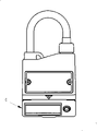
At present, in micro_computer five_proof locking field, the padlock that anti-misoperation locking device is used, as shown in Figure 1, the mechanical part and the electronic unit that include lock body 1 and be arranged on 1 li of lock body, described electronic unit includes chip, the bottom of lock body 1, the opening 6 of release jack 2 and cavity is open, has following drawback:
At first, under the adverse circumstances such as sand and dust, humidity, lock body inside particularly enters dust and insect easily from keyhole, makes to be difficult for the movable bite of lock body inner structure parts maybe can not opening.
Secondly, enter sand and dust, insect etc. in the chip chamber easily, influence computer key to read sign indicating number, can not read chip or reading mistake, error in judgement, lockset can not be opened or open by mistake to lockset.
Summary of the invention
The purpose of this utility model is to provide a kind of anti-misoperation locking padlock, can prevent effectively that sand and dust and insect etc. from entering lock body inside, can effectively protect interior frame for movement of lock body and chip not to be subjected to external interference, infringement.
The utility model is achieved through the following technical solutions:
A kind of anti-misoperation locking padlock includes lock body, latch hook, unlocking mechanism and electronic unit; Be provided with cavity that described electronic unit is installed and the release jack that described unlocking mechanism is installed in the described lock body; The opening of described cavity and release jack is positioned on the outside wall surface of described lock body; Wherein, described anti-misoperation locking padlock also includes dust cover, and described dust cover covers the outside of lock body outside wall surface, and the opening of described cavity and release jack is airtight.
The opening of described cavity and release jack, i.e. keyhole and chip hole are positioned at the bottom surface of lock body, and described dust cover covers the lock body bottom.
Described electronic unit includes Wireless code sheet, and described Wireless code sheet is arranged in described cavity.
The beneficial effects of the utility model are as follows:
A kind of anti-misoperation locking padlock of the present utility model, the shape of lock body is similar to common Mechanical ring latch, has one and parts-dust cover of cooperating of lock body in lock body bottom, the state that is pinning, dust cover is fastened on lock body bottom, prevents that foreign material such as sand and dust from entering lock body inside, the protection lockset; In the time of need unblanking, then the lock body bottom is opened, expose keyhole and chip hole, can insert key unlocking, easy to use.
Description of drawings
The structural representation of accompanying drawing 1 prior art padlock;
Accompanying drawing 2 is a kind of anti-misoperation locking padlock of the utility model and computer key fit structure schematic diagram;
Accompanying drawing 3 is the overall structure schematic diagram of a kind of anti-misoperation locking padlock of the utility model;
Accompanying drawing 4 is the dust cover opening side-looking structural representation of a kind of anti-misoperation locking padlock of the utility model;
Accompanying drawing 5 is faced structural representation for the dust cover opening of a kind of anti-misoperation locking padlock of the utility model;
Accompanying drawing 6 is on the lock body of a kind of anti-misoperation locking padlock of the utility model, with the main TV structure schematic diagram of dust cover fit;
Accompanying drawing 7 is the dust cover side-looking structural representation of a kind of anti-misoperation locking padlock of the utility model;
Accompanying drawing 8 is the dust cover master TV structure schematic diagram of a kind of anti-misoperation locking padlock of the utility model;
Accompanying drawing 9 is the dust cover perspective view of a kind of anti-misoperation locking padlock of the utility model.
Description of reference numerals:
1 lock body, 2 unlocking mechanisms, 3 release jacks, 4 dust covers, 5 chips, 6 cavitys, 7 computer keys, 8 trip levers, 9 probes, 10, unlock button, 11 Baltimore grooves, 41 folding trace structures, 42 buckles one, 43 buckles two, 44 side chambeies, 45 cylindrical cavities, 46 square frame shape boss, 47 circle framework boss, 48 are scratched hand.
The specific embodiment
Ask for an interview Fig. 2 to Fig. 3, a kind of anti-misoperation locking padlock includes lock body 1, latch hook, unlocking mechanism 2 and electronic unit; The release slotting 3 that is provided with the cavity 6 that described electronic unit is installed in the described lock body 1 and described unlocking mechanism 2 is installed; The opening of described cavity 6 and release jack 3 is positioned on the outside wall surface of described lock body 1; Wherein, described anti-misoperation locking padlock also includes dust cover 4, and described dust cover 4 covers the outside of lock body 1 outside wall surface, and the opening of described cavity 6 and release jack 3 is airtight.
The opening of described cavity 6 and release jack 3, i.e. key aperture and chip aperture are positioned at the bottom surface of lock body 1, and described dust cover 4 covers lock body 1 bottom.
Described electronic unit includes Wireless code sheet 5, and described Wireless code sheet 5 is arranged in described cavity.
As Fig. 4, shown in Figure 5, described lock body 1 two side walls is provided with the inner groovy that label is installed, and label embeds described inner groovy and installs.
As Fig. 4, Fig. 5, Fig. 6, Fig. 7, Fig. 8, shown in Figure 9, described cavity 6 is a rectangular cavity, and described release jack 3 is a cylindrical hole; Described key aperture is a circular port, and the chip aperture is a square orifice.
Described dust cover 4 is the plastic device of a loose-leaf shape, includes two movable sheets and is formed by connecting; Movable sheet one is the lid of dust cover band itself for dustproof cover body, movable sheet two; Baltimore groove 11 is set around the base of lock body 1; Dustproof cover body fastens with Baltimore groove 11 by being arranged on its peripheral buckle 1, and dust cover is fixed on the lock body, and described dustproof cover body is provided with the cylindrical cavity 45 and the square chamber 44 of docking with key aperture and chip aperture; Described lid and dustproof cover body are flexible coupling by folding trace structure 41; Described lid is provided with a square frame shape boss 46, and the edge of square frame shape boss 46 is provided with the buckle 2 43 of projection, can cooperate on the chamber, the side of being fixed on 44; Described lid also is provided with a circle framework boss 47, and 47 cooperations of circle framework boss are fixed on the cylindrical cavity 45.
Dust cover is under closure state, and on limit in chamber, buckle 2 43 side of being stuck in 44, simultaneously, square frame shape boss 46 and 44 driving fits of square chamber, circle framework boss 47 and cylindrical cavity 45 driving fits guarantee that dust cover inside effectively separates with the external world, protection lock body inside on it.If will open, the stingy hand 48 that can press...with one's finger can be opened.
As Fig. 2, the utility model in use, be used by computer key 7 and the utility model, the utility model is installed on the manual-operating mechanism of equipment such as isolating switch, disconnecting link, when needs are operated these equipment, must open the utility model with computer key 7, could operate these equipment; When needs " release " during by the equipment of locking, open dust cover 4 earlier, expose release jack 3 and cavity 6, computer key 7 is inserted in the utility model, wherein the trip lever 8 of computer key 7 inserts in the release jack 3 of lock bodies bottom; The probe 9 of computer key 7 inserts in the cavity 6 of lock body simultaneously, close with the chip 5 of cavity 6 bottoms, as shown in Figure 2, computer key 7 collects this coded message by the probe on it 9, and carry out five anti-logics and judge, confirm that whether this operate the match operation condition.If meet, computer key can rotate the conduction trip lever, at this moment, presses the unlock button 10 on the computer key, and trip lever 8 drives unlocking mechanism 2, lock is opened, and then reached the equipment purpose of " release " institute locking.Otherwise, then can't " release ".
Above-mentioned listed specific implementation is nonrestrictive, and to one skilled in the art, in not departing from the utility model scope, various improvement and the variation carried out all belong to protection domain of the present utility model.
Claims (9)
1, a kind of anti-misoperation locking padlock includes lock body (1), latch hook, unlocking mechanism (2) and electronic unit; The release slotting (3) that is provided with the cavity (6) that described electronic unit is installed in the described lock body (1) and described unlocking mechanism (2) is installed; The opening of described cavity (6) and release jack (3) is positioned on the outside wall surface of described lock body () 1; It is characterized in that: described anti-misoperation locking padlock also includes dust cover (4), and described dust cover (4) covers the outside of lock body (1) outside wall surface, and the opening of described cavity (6) and release jack (3) is airtight.
2, a kind of anti-misoperation locking padlock as claimed in claim 1 is characterized in that: the opening of described cavity (6) and release jack (3), i.e. and key aperture and chip aperture are positioned at the bottom surface of lock body (1), and described dust cover (4) covers lock body (1) bottom.
3, a kind of anti-misoperation locking padlock as claimed in claim 2, it is characterized in that: described electronic unit includes Wireless code sheet (5), and described Wireless code sheet (5) is arranged in described cavity.
4, as claim 1 or 2 or 3 described a kind of anti-misoperation locking padlocks, it is characterized in that: described lock body (1) two side walls is provided with the inner groovy that label is installed, and label embeds described inner groovy and installs.
5, as claim 1 or 2 or 3 described a kind of anti-misoperation locking padlocks, it is characterized in that: described cavity (6) is a rectangular cavity, and described release jack (3) is a cylindrical hole; Described key aperture is a circular port, and the chip aperture is a square orifice.
6, a kind of anti-misoperation locking padlock as claimed in claim 5, it is characterized in that: described dust cover (4) is the plastic device of a loose-leaf shape, includes two movable sheets and is formed by connecting; Movable sheet one is the lid of dust cover band itself for dustproof cover body, movable sheet two.
7, a kind of anti-misoperation locking padlock as claimed in claim 6 is characterized in that: Baltimore groove (11) is set around the base of described lock body (1); Dustproof cover body fastens with Baltimore groove (11) by being arranged on its peripheral buckle one (42), and dust cover is fixed on the lock body, and described dustproof cover body is provided with cylindrical cavity (45) and square chamber (44) of docking with key aperture and chip aperture.
8, a kind of anti-misoperation locking padlock as claimed in claim 7, it is characterized in that: described lid and dustproof cover body are flexible coupling by folding trace structure (41).
9, a kind of anti-misoperation locking padlock as claimed in claim 7 is characterized in that: described lid is provided with a square frame shape boss (46), and the edge of square frame shape boss (46) is provided with the buckle two (43) of projection, can cooperate on the chamber, the side of being fixed on (44); Described lid also is provided with a circle framework boss (47), and circle framework boss (47) cooperation is fixed on the cylindrical cavity (45).
Priority Applications (1)
| Application Number | Priority Date | Filing Date | Title |
|---|---|---|---|
| CNU2008200499503U CN201218001Y (en) | 2008-06-30 | 2008-06-30 | Anti-misoperation padlock |
Applications Claiming Priority (1)
| Application Number | Priority Date | Filing Date | Title |
|---|---|---|---|
| CNU2008200499503U CN201218001Y (en) | 2008-06-30 | 2008-06-30 | Anti-misoperation padlock |
Publications (1)
| Publication Number | Publication Date |
|---|---|
| CN201218001Y true CN201218001Y (en) | 2009-04-08 |
Family
ID=40540836
Family Applications (1)
| Application Number | Title | Priority Date | Filing Date |
|---|---|---|---|
| CNU2008200499503U Expired - Lifetime CN201218001Y (en) | 2008-06-30 | 2008-06-30 | Anti-misoperation padlock |
Country Status (1)
| Country | Link |
|---|---|
| CN (1) | CN201218001Y (en) |
Cited By (9)
| Publication number | Priority date | Publication date | Assignee | Title |
|---|---|---|---|---|
| CN102373843A (en) * | 2011-11-01 | 2012-03-14 | 金泰祥精密五金(昆山)有限公司 | Name-plate lock |
| CN102383667A (en) * | 2010-11-21 | 2012-03-21 | 马铮 | Electronic radio-frequency lock and key thereof |
| CN103556881A (en) * | 2013-10-31 | 2014-02-05 | 北京微能汇通电力技术有限公司 | Ring latch device |
| CN104040097A (en) * | 2011-10-28 | 2014-09-10 | 阿布莱有限公司 | Padlock |
| CN104153656A (en) * | 2014-07-08 | 2014-11-19 | 长园共创电力安全技术股份有限公司 | Telescopic block pin type lock |
| CN104420727A (en) * | 2013-09-06 | 2015-03-18 | 珠海优特电力科技股份有限公司 | Latch-type fixed lock provided with wireless code piece, anti-error locking system and working method |
| CN105507686A (en) * | 2014-10-14 | 2016-04-20 | 珠海优特电力科技股份有限公司 | Anti-misoperation padlock |
| CN105569461A (en) * | 2014-10-14 | 2016-05-11 | 珠海优特电力科技股份有限公司 | Anti-maloperation padlock |
| CN109723294A (en) * | 2018-12-29 | 2019-05-07 | 厦门硕锋科技有限公司 | A kind of semi-enclosed smart lock remotely controlled based on cell phone application |
-
2008
- 2008-06-30 CN CNU2008200499503U patent/CN201218001Y/en not_active Expired - Lifetime
Cited By (17)
| Publication number | Priority date | Publication date | Assignee | Title |
|---|---|---|---|---|
| CN102383667A (en) * | 2010-11-21 | 2012-03-21 | 马铮 | Electronic radio-frequency lock and key thereof |
| CN104040097A (en) * | 2011-10-28 | 2014-09-10 | 阿布莱有限公司 | Padlock |
| US9670699B2 (en) | 2011-10-28 | 2017-06-06 | Abloy Oy | Padlock |
| CN104040097B (en) * | 2011-10-28 | 2017-04-12 | 阿布莱有限公司 | Padlock |
| CN102373843A (en) * | 2011-11-01 | 2012-03-14 | 金泰祥精密五金(昆山)有限公司 | Name-plate lock |
| CN104420727B (en) * | 2013-09-06 | 2017-01-04 | 珠海优特电力科技股份有限公司 | The fixing lock of keeper formula, anti-error locking system and method for work equipped with Wireless code sheet |
| CN104420727A (en) * | 2013-09-06 | 2015-03-18 | 珠海优特电力科技股份有限公司 | Latch-type fixed lock provided with wireless code piece, anti-error locking system and working method |
| CN103556881A (en) * | 2013-10-31 | 2014-02-05 | 北京微能汇通电力技术有限公司 | Ring latch device |
| CN103556881B (en) * | 2013-10-31 | 2017-01-11 | 北京微能汇通电力技术有限公司 | Ring latch device |
| CN104153656A (en) * | 2014-07-08 | 2014-11-19 | 长园共创电力安全技术股份有限公司 | Telescopic block pin type lock |
| CN104153656B (en) * | 2014-07-08 | 2016-09-07 | 长园共创电力安全技术股份有限公司 | Flexible bail type lock |
| CN105569461A (en) * | 2014-10-14 | 2016-05-11 | 珠海优特电力科技股份有限公司 | Anti-maloperation padlock |
| CN105507686A (en) * | 2014-10-14 | 2016-04-20 | 珠海优特电力科技股份有限公司 | Anti-misoperation padlock |
| CN105507686B (en) * | 2014-10-14 | 2017-09-22 | 珠海优特电力科技股份有限公司 | Anti-error padlock |
| CN105569461B (en) * | 2014-10-14 | 2017-09-22 | 珠海优特电力科技股份有限公司 | Anti-error padlock |
| CN109723294A (en) * | 2018-12-29 | 2019-05-07 | 厦门硕锋科技有限公司 | A kind of semi-enclosed smart lock remotely controlled based on cell phone application |
| CN109723294B (en) * | 2018-12-29 | 2020-11-13 | 厦门硕锋科技有限公司 | Semi-closed intelligent lock based on cell-phone APP remote control |
Similar Documents
| Publication | Publication Date | Title |
|---|---|---|
| CN201218001Y (en) | Anti-misoperation padlock | |
| CN202043391U (en) | Casing structure | |
| CN1874658B (en) | Structure of battery corer of portable type electronic equipment | |
| CN101123143A (en) | Latch-release actuating apparatus | |
| CN110512655B (en) | Intelligent well lid | |
| US20200074776A1 (en) | Electronic keypad assembly for lockset | |
| US8251408B2 (en) | Battery cover latch mechanism and portable electronic device using same | |
| CN102599709A (en) | Locking device used for box body | |
| CN201343907Y (en) | Electric anti-mistake hand-held unlocking key | |
| US20100124699A1 (en) | Battery cover latching mechanism | |
| CN106567625A (en) | Electronic cabinet lock capable of being unlocked in electromagnetically driven mode | |
| JP5717170B2 (en) | Electronic equipment and case | |
| CN101998915A (en) | Electronic key for the remote control of vehicles | |
| CN207499602U (en) | A kind of shell mechanism of intelligent door lock | |
| CN105184933A (en) | Fingerprint lock | |
| CN204990466U (en) | Fingerprint lock | |
| CN102086718B (en) | Electronic lock hole protective device with electromagnetic clutch | |
| CN212507826U (en) | Lock for motorcycle | |
| CN205531715U (en) | Changeable tool to lock of sign | |
| CN103381924B (en) | There is the chest of rotation locking device | |
| CN210118003U (en) | Fingerprint lock | |
| JP2016079666A (en) | Mounting structure of plane-mounted unit | |
| CN207499632U (en) | A kind of intelligent security guard electric control door lock | |
| CN217106562U (en) | Electronic dead glove box structure of lock that prevents | |
| CN216901337U (en) | Printing device and printer |
Legal Events
| Date | Code | Title | Description |
|---|---|---|---|
| C14 | Grant of patent or utility model | ||
| GR01 | Patent grant | ||
| CX01 | Expiry of patent term | ||
| CX01 | Expiry of patent term |
Granted publication date: 20090408 |