CN201209520Y - Anti-tipping suspending type wind generating set - Google Patents
Anti-tipping suspending type wind generating set Download PDFInfo
- Publication number
- CN201209520Y CN201209520Y CNU2008200801550U CN200820080155U CN201209520Y CN 201209520 Y CN201209520 Y CN 201209520Y CN U2008200801550 U CNU2008200801550 U CN U2008200801550U CN 200820080155 U CN200820080155 U CN 200820080155U CN 201209520 Y CN201209520 Y CN 201209520Y
- Authority
- CN
- China
- Prior art keywords
- wind
- float
- unit
- tipping
- suspended
- Prior art date
- Legal status (The legal status is an assumption and is not a legal conclusion. Google has not performed a legal analysis and makes no representation as to the accuracy of the status listed.)
- Expired - Lifetime
Links
Images


Classifications
-
- Y—GENERAL TAGGING OF NEW TECHNOLOGICAL DEVELOPMENTS; GENERAL TAGGING OF CROSS-SECTIONAL TECHNOLOGIES SPANNING OVER SEVERAL SECTIONS OF THE IPC; TECHNICAL SUBJECTS COVERED BY FORMER USPC CROSS-REFERENCE ART COLLECTIONS [XRACs] AND DIGESTS
- Y02—TECHNOLOGIES OR APPLICATIONS FOR MITIGATION OR ADAPTATION AGAINST CLIMATE CHANGE
- Y02E—REDUCTION OF GREENHOUSE GAS [GHG] EMISSIONS, RELATED TO ENERGY GENERATION, TRANSMISSION OR DISTRIBUTION
- Y02E10/00—Energy generation through renewable energy sources
- Y02E10/70—Wind energy
- Y02E10/72—Wind turbines with rotation axis in wind direction
-
- Y—GENERAL TAGGING OF NEW TECHNOLOGICAL DEVELOPMENTS; GENERAL TAGGING OF CROSS-SECTIONAL TECHNOLOGIES SPANNING OVER SEVERAL SECTIONS OF THE IPC; TECHNICAL SUBJECTS COVERED BY FORMER USPC CROSS-REFERENCE ART COLLECTIONS [XRACs] AND DIGESTS
- Y02—TECHNOLOGIES OR APPLICATIONS FOR MITIGATION OR ADAPTATION AGAINST CLIMATE CHANGE
- Y02E—REDUCTION OF GREENHOUSE GAS [GHG] EMISSIONS, RELATED TO ENERGY GENERATION, TRANSMISSION OR DISTRIBUTION
- Y02E10/00—Energy generation through renewable energy sources
- Y02E10/70—Wind energy
- Y02E10/727—Offshore wind turbines
Abstract
The utility model discloses an anti-overturning suspended wind turbine unit which relates to a wind power generation technology; the wind turbine unit comprises a wind wheel, a tower, a float, a diagonal steel cable, a balancing pole and a positive elastic steel cable; a wind machine is fixed on the float; the float is tied to a diagonal concrete pier in the depth of the sea by the diagonal steel cable with a certain elasticity; the balancing pole is fixed right below the float; the lower end of the balancing pole is tied to a positive concrete pier right below by the positive elastic steel cable; once the wind speed is quite high, the unit largely inclines, the positive elastic steel cable is stretched, to produce pulling force F; the pulling force F urges the unit to return to the normal position. The suspended wind turbine unit has the function of overturning resistance, so that the marine suspended wind turbine unit can prevent overall overturning and even crash accident when running at quite high wind speed, thereby improving the safety running of the marine suspended wind turbine unit.
Description
Technical field
The utility model relates to a kind of wind power generating set, particularly a kind of balancing pole and just drawing the elasticity wirerope to prevent tipping suspended wind unit of utilizing.
Background technique
Along with China's rapid economy development, the contradiction of the energy and environment becomes increasingly conspicuous, and preserves the ecological environment, and promotes the construction of resource-conserving and environment-friendly society, is the important content that the Economic Growth in China mode changes.Wind energy is a clean energy resource with fastest developing speed in the renewable energy sources, also is the generation mode that has large-scale development and commercialized development prospect most.To the end of the year 2007, the wind-powered electricity generation electric motor power of China has reached 5,000,000 kW, has only just realized 5 years targets that Eleventh-Five Year Plan is formulated with two years.China's wind energy on the sea aboundresources, 10 meters about 7.5 hundred million kW of highly available coastal waters wind energy resources, be three times of land wind-resources, along with the maturation gradually of offshore wind farm technology and the decline of cost, wind energy on the sea will inevitably become China's important component part in the energy resource structure in the future.
Compare with land wind-powered electricity generation, the research of offshore wind farm is started late.At present, the U.S., Denmark, Sweden, Germany, Britain, France, Holland, Belgium and Japan and other countries are all carried out the research of offshore wind farm.The suspended wind unit is installed simply, is convenient to migration, and manufacturing is about 1/3rd of a marine tower-type wind-powered electricity generation unit with installation cost.
Fig. 1 (a) uses more a kind of typical floated wind power generating set schematic representation at present.Wherein, wind wheel 1, pylon 2, float 3, oblique rollering steel cable 4, tiltedly draw concrete pier 5.The wind-force electrical machinery that wind wheel 1, pylon 2 constitutes is fixed on the float 3, and float 3 usefulness have certain flexible three oblique rollering steel cables 4 and tie up to three of seabed respectively and tiltedly draw on the concrete pier 5, and elasticity oblique rollering steel cable 4 permission floats 3 have the drift of a little in the horizontal direction.The design of centre of gravity of this suspended wind unit is below the water surface, to guarantee that unit can tipping under slight tilt condition.But, in case wind speed is excessive, cause the inclination of unit bigger than normal, be easy to take place the whole tipping of wind-powered electricity generation unit even ruin the machine accident, shown in Fig. 1 (b).
The model utility content
In order to overcome the defective that prior art exists, the purpose of this utility model is to realize the safe operation of suspended wind unit, for this reason, discloses a kind of anti-tipping suspended wind unit that has balancing pole and just drawing the Elastic Steel cable structure.
For achieving the above object, technical solution of the present utility model is:
A kind of anti-tipping suspended wind unit, comprise wind wheel, pylon, float, oblique rollering steel cable, the wind-force electrical machinery that wind wheel, pylon constitute is fixed on the float, float ties up on the concrete pier in seabed with having certain flexible oblique rollering steel cable, it also comprises balancing pole, just draws elasticity wirerope and just drawing concrete pier, balancing pole upper end be fixed on float under, the balancing pole lower end is with just drawing the elasticity wirerope to tie up on the seabed concrete pier under it, utilize balancing pole, just draw elasticity wirerope and just drawing concrete pier, make the suspended wind unit have anti-tipping function.
The utility model compared with prior art, have following conspicuous substantive distinguishing features and remarkable advantage: anti-tipping suspended wind unit swims in the sea, wind speed is excessive to cause the inclination of unit bigger than normal, at this moment, just drawing the elasticity wirerope to be stretched, producing the tensile force f shown in Fig. 2 (b), this tensile force f will force unit to return to the normal position, can effectively prevent the whole tipping of wind-powered electricity generation unit and ruin the generation of machine accident, improve the operational safety performance of wind-powered electricity generation unit.
Description of drawings
Fig. 1 is a kind of suspended wind unit schematic representation; Wherein:
Fig. 1 (a) is the suspended wind unit schematic representation under the normal state;
Fig. 1 (b) is the suspended wind unit schematic representation under the tilt state;
Fig. 2 is an anti-tipping suspended wind unit schematic representation of the present utility model; Wherein:
Fig. 2 (a) is the suspended wind unit schematic representation under the utility model normal state;
Fig. 2 (b) is the suspended wind unit schematic representation of the utility model under tilt state;
Fig. 3 is a kind of suspended wind unit tipping schematic representation;
Fig. 4 is the anti-tipping schematic representation of anti-tipping suspended wind unit of the present utility model.
Embodiment
Below in conjunction with accompanying drawing the utility model is described in detail, be to be noted that described embodiment only is being convenient to understanding of the present utility model, and it is not played any qualification effect.
Be depicted as a kind of anti-tipping suspended wind set structure schematic representation of the present utility model as Fig. 2 (a), wherein: wind wheel 1, pylon 2, float 3, oblique rollering steel cable 4, concrete pier 5, balancing pole 6, just draw elasticity wirerope 7, just draw concrete pier 71.The wind-force electrical machinery that wind wheel 1, pylon 2 constitute is fixed on the float 3, float 3 usefulness have certain flexible many oblique rollering steel cables 4 and tie up to tiltedly drawing on the concrete pier 5 of seabed respectively, balancing pole 6 upper ends be fixed on float 3 under, is just drawing on the concrete pier 71 with the seabed of just drawing elasticity wirerope 7 to tie up under it balancing pole 6 lower ends.
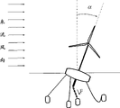
The suspended wind unit is the meeting run-off the straight when operation, and as shown in Figure 3, α is the angle of inclination among the figure.Inclination alpha is excessive when wind speed is bigger than normal, causes wind-powered electricity generation unit tipping to cause the machine accident of ruining.Aerodynamic loading during according to the design parameter of wind-powered electricity generation unit and operation distributes, and can calculate inclination alpha.
Fig. 3 is existing a kind of suspended wind unit generation tipping accident schematic representation, shown in be not increase balancing pole 6, just draw elasticity wirerope 7 and just drawing a kind of existing suspended wind unit of the anti-tipping structure of concrete pier 71, when the incoming flow wind speed was big, tipping can take place in unit.
Fig. 4 is the anti-tipping schematic representation of anti-tipping suspended wind unit of the present utility model, shown in the anti-tipping suspended wind unit anti-tipping structure of having set up balancing pole 6, just having drawn elasticity wirerope 7 and just drawing concrete pier 71, when wind speed is big, the run-off the straight of wind-powered electricity generation unit, inclination alpha is excessive, just drawing elasticity wirerope 7 to be stretched, produce tensile force f as shown in Figure 4, this tensile force f will force unit to return to the normal position, this wind-powered electricity generation unit has well anti-tipping performance, has promoted the operational safety performance of wind-powered electricity generation unit greatly.
In the anti-tipping suspended wind unit of the present utility model, the length l of balancing pole is expressed as:
l=a×L
In the formula, L be float to the seabed distance, a is for according to the design parameter of anti-tipping suspended wind unit and the coefficient that operating conditions calculates thereof, the span of a is 10
-10~1.5.The concrete numeral of a is determined by following formula:
Just drawing the length h of elasticity wirerope to be expressed as:
h=γ(L-l) (2)
Go up in (1), (2) two formulas, β is factor beta=0.1~1.5; γ is coefficient gamma=1.0~1.1; ρ is a density of sea water, the t/m of unit
3V is the volume of float, unit: m
3H is the pylon height, unit: m; G is a wind-powered electricity generation unit weight, unit: t; L be float to the seabed distance, unit: m.
The anti-tipping construction manufacturing method of a kind of anti-tipping suspended wind unit of the present utility model, it comprises the steps:
Step 1: balancing pole be fixed on float under, and according to the design parameter of anti-tipping suspended wind unit and the length of operating conditions calculated equilibrium bar thereof;
Step 2: just drawing elasticity wirerope upper end link balancing pole lower end, just draw on the concrete pier in the seabed that the lower end is fixed under the balancing pole, and calculate the length of just drawing the elasticity wirerope according to the design parameter and the operating conditions thereof of anti-tipping suspended wind unit.
Embodiment 1: an anti-tipping suspended wind unit of the present invention, and heavy 17t, the high 70m of pylon, the volume of float are 22m
3, density of sea water is 1.03t/m
3, float is 20m to the seabed distance, in the design object, at 75 rev/mins of wind speed rounds, wind sweeping area 8000m
2, the tipping accident can not take place in the operating mode leeward group of motors of incoming flow wind speed 50m/s.
According to the design parameter and the operating conditions thereof of anti-tipping suspended wind unit, by
In the present embodiment, β=0.1, the coefficient a=0.104 that γ=1.0 calculate, the length l=0.104L of balancing pole is then just drawing length h=γ (the L-l)=0.896L of elasticity wirerope.The wind-powered electricity generation unit is in running like this, when the inclination angle is α=20 °, just drawing elasticity wirerope 7 will produce tensile force f, and this tensile force f will force unit to return to the normal position, guarantee the safety in operation of wind-powered electricity generation unit.
Embodiment 2: an anti-tipping suspended wind unit of the present invention, and heavy 25t, the high 50m of pylon, the volume of float are 27m
3, density of sea water is 1.03t/m
3, float is 100m to the seabed distance, in the design object, at 75 rev/mins of wind speed rounds, wind sweeping area 8000m
2, the tipping accident can not take place in the operating mode leeward group of motors of incoming flow wind speed 50m/s.
According to the design parameter and the operating conditions thereof of anti-tipping suspended wind unit, by
In the present embodiment, β=1.5, the coefficient a=0.556 that γ=1.05 calculate, the length l=0.556L of balancing pole is then just drawing length h=γ (the L-l)=0.466L of elasticity wirerope.The wind-powered electricity generation unit is in running like this, when the inclination angle is α=20 °, just drawing elasticity wirerope 7 will produce tensile force f, and this tensile force f will force unit to return to the normal position, guarantee the safety in operation of wind-powered electricity generation unit.
The above; it only is the embodiment in the utility model; but protection domain of the present utility model is not limited thereto; anyly be familiar with the people of this technology in the disclosed technical scope of the utility model; the conversion that can do or replacement; all should be encompassed in of the present utility model comprising within the scope, therefore, protection domain of the present utility model should be as the criterion with the protection domain of claims.
Claims (1)
1, a kind of anti-tipping suspended wind unit, comprise wind wheel, pylon, float, oblique rollering steel cable, the wind-force electrical machinery that wind wheel, pylon constitute is fixed on the float, float ties up to tiltedly drawing on the concrete pier of seabed with having certain flexible oblique rollering steel cable, it is characterized in that, also comprise balancing pole, just draw elasticity wirerope and just drawing concrete pier, balancing pole upper end be fixed on float under, just draw on the concrete pier with the seabed of just drawing the elasticity wirerope to tie up under it the balancing pole lower end.
Priority Applications (1)
| Application Number | Priority Date | Filing Date | Title |
|---|---|---|---|
| CNU2008200801550U CN201209520Y (en) | 2008-04-23 | 2008-04-23 | Anti-tipping suspending type wind generating set |
Applications Claiming Priority (1)
| Application Number | Priority Date | Filing Date | Title |
|---|---|---|---|
| CNU2008200801550U CN201209520Y (en) | 2008-04-23 | 2008-04-23 | Anti-tipping suspending type wind generating set |
Publications (1)
| Publication Number | Publication Date |
|---|---|
| CN201209520Y true CN201209520Y (en) | 2009-03-18 |
Family
ID=40480253
Family Applications (1)
| Application Number | Title | Priority Date | Filing Date |
|---|---|---|---|
| CNU2008200801550U Expired - Lifetime CN201209520Y (en) | 2008-04-23 | 2008-04-23 | Anti-tipping suspending type wind generating set |
Country Status (1)
| Country | Link |
|---|---|
| CN (1) | CN201209520Y (en) |
Cited By (3)
| Publication number | Priority date | Publication date | Assignee | Title |
|---|---|---|---|---|
| CN101566130B (en) * | 2008-04-23 | 2010-12-22 | 中国科学院工程热物理研究所 | Anti-tilting suspended wind turbine unit |
| CN103314212A (en) * | 2010-11-05 | 2013-09-18 | 独立行政法人海上技术安全研究所 | Roll and yaw damper of wind turbine and floating offshore wind turbine |
| CN111559469A (en) * | 2014-05-27 | 2020-08-21 | 埃斯特科股份公司 | Floating structure and installation method thereof |
-
2008
- 2008-04-23 CN CNU2008200801550U patent/CN201209520Y/en not_active Expired - Lifetime
Cited By (4)
| Publication number | Priority date | Publication date | Assignee | Title |
|---|---|---|---|---|
| CN101566130B (en) * | 2008-04-23 | 2010-12-22 | 中国科学院工程热物理研究所 | Anti-tilting suspended wind turbine unit |
| CN103314212A (en) * | 2010-11-05 | 2013-09-18 | 独立行政法人海上技术安全研究所 | Roll and yaw damper of wind turbine and floating offshore wind turbine |
| CN103314212B (en) * | 2010-11-05 | 2016-01-20 | 国立研究开发法人海上技术安全研究所 | Float type offshore wind energy plant |
| CN111559469A (en) * | 2014-05-27 | 2020-08-21 | 埃斯特科股份公司 | Floating structure and installation method thereof |
Similar Documents
| Publication | Publication Date | Title |
|---|---|---|
| CN101649813B (en) | Integrated system for generating electricity by current, sea wave as well as tide kinetic energy and wind and solar energy | |
| CN101566130B (en) | Anti-tilting suspended wind turbine unit | |
| CN202040026U (en) | Comprehensive utilization system for sea energy | |
| CN102392796B (en) | Offshore suspension type wind generating set based on active balance control | |
| CN206419157U (en) | A kind of damp integration generating device of floatation type stormy waves | |
| CN103010417A (en) | Offshore wind power floating foundation suitable for small water plane with water depth below 100m | |
| CN102285429A (en) | Floating type supporting structure for marine windmill | |
| CN108316336A (en) | A kind of novel lattice offshore wind turbine buoyant foundation composite structure | |
| CN107575337A (en) | Based on tension leg platform (TLP) vertical axis windmill and vertical level two to wave-energy power generation integrated morphology | |
| CN109653960B (en) | Wind energy and wave energy combined power generation device based on jacket foundation | |
| CN2703137Y (en) | Hydroelectric generating set | |
| CN104763595A (en) | Self-adapted wind collection type overwater wind power station | |
| CN102454553B (en) | Floating type wind power plant | |
| CN201209520Y (en) | Anti-tipping suspending type wind generating set | |
| CN111305996A (en) | Energy-gathering type sea wave gravity power generation system and marine ecological platform | |
| CN103243732A (en) | Installing method of marine anemometer tower base structure | |
| CN201416515Y (en) | Offshore wind power generating set | |
| CN107201991A (en) | A kind of new marine windmill floating platform | |
| CN211442693U (en) | Offshore flexible self-floating photovoltaic power generation system | |
| CN217477518U (en) | Floating type photovoltaic supporting structure combined with offshore wind power foundation | |
| CN110821744A (en) | Scalable floating trend can power generation facility | |
| CN212337524U (en) | Swing type sea wave generator | |
| CN108240293A (en) | A kind of gravity type offshore wind turbine platform and its construction method | |
| CN114644089A (en) | Offshore wind and solar complementary power generation system and offshore floating bearing platform | |
| CN207004720U (en) | A kind of taper damps wave-power device |
Legal Events
| Date | Code | Title | Description |
|---|---|---|---|
| C14 | Grant of patent or utility model | ||
| GR01 | Patent grant | ||
| CX01 | Expiry of patent term | ||
| CX01 | Expiry of patent term |
Granted publication date: 20090318 |