CN201202762Y - Bumper absorber with nine-shift adjustable mechanism - Google Patents
Bumper absorber with nine-shift adjustable mechanism Download PDFInfo
- Publication number
- CN201202762Y CN201202762Y CNU2008200871197U CN200820087119U CN201202762Y CN 201202762 Y CN201202762 Y CN 201202762Y CN U2008200871197 U CNU2008200871197 U CN U2008200871197U CN 200820087119 U CN200820087119 U CN 200820087119U CN 201202762 Y CN201202762 Y CN 201202762Y
- Authority
- CN
- China
- Prior art keywords
- base
- vibration damper
- spool
- grades
- assembly
- Prior art date
- Legal status (The legal status is an assumption and is not a legal conclusion. Google has not performed a legal analysis and makes no representation as to the accuracy of the status listed.)
- Expired - Lifetime
Links
Images
Abstract
The utility model relates to a damper with a nine-gear adjustable mechanism, comprising an operating cylinder (13) and a liquid storage tube (14) arranged on the external side of the operating cylinder; a piston rod (20) is arranged in the center of the interior of the operating cylinder (13); the lower end of the piston rod (20) is provided with a piston valve assembly (5); the bottom end of the operating cylinder (13) is connected with a compression valve assembly (7); the bottom end of the liquid storage tube (14) is connected with a base (11); the damper is characterized in that an adjustor assembly (19) is arranged in the middle of the base (11). The knob of the adjuster assembly is rotated to enable the damper to generate different damping forces according to different road surfaces or different weights applied on the damper, so as to realize different damping effects; thereby, the best damping effect is realized; the comfort property is improved.
Description
Technical field
The utility model relates to a kind of vibration damper, is a kind of vibration damper that has nine grades of adjusting mechanisms specifically.
Background technique
Vibration damper all has at aspects such as automobile, motorcycle, oil drillings very widely to be used, and especially in automobile industry, vibration damper is not the weight that is used for supporting vehicle body, but the concussion when being used for suppressing bounce-back after the spring shock-absorbing and absorb the energy of road shocks.If you drove the car that vibration damper has broken down, you just can know from experience automobile by the spring that each cheats the hole, the back repercussions that rise and fall ripple, and vibration damper is used for suppressing this spring just.There is not the bounce-back of vibration damper with uncontrollable spring, when running into rugged road surface, automobile will produce serious spring, cross the forfeiture that also can cause tire earth-grasping force and tracking when bending, will make when driver and passenger are sat very uncomfortable like this because of the concussion about the spring; Certainly, if vibration damper is intact, and the damping force one of vibration damper regularly, and when bearing Different Weight or during at different road traveling, it is more uncomfortable that driver and passenger will be felt, the travelling comfort of taking is poor.
Summary of the invention
The utility model has solved the nonadjustable problem of damping force of the vibration damper of prior art existence, a kind of vibration damper that has nine grades of adjusting mechanisms is provided, it can make the damping force of vibration damper on different road surfaces, or produce different damping forces when bearing different weight, to reach different effectiveness in vibration suppression, make damping reach best effect like this, improved travelling comfort.
Above-mentioned technical purpose of the present utility model mainly solves by the following technical programs: a kind of vibration damper that has nine grades of adjusting mechanisms, comprise clutch release slave cylinder and place its outer surge drum, be provided with piston rod in the clutch release slave cylinder central interior, be provided with the piston valve assembly in the lower end of piston rod, described clutch release slave cylinder bottom is connected with the compression assembly, the surge drum bottom is connected with base, it is characterized in that being provided with REG Regulator Assembly in the middle of the described base.Described REG Regulator Assembly comprises knob and connected spool, is provided with link between this knob and the spool, and the described spool outside is connected base by spring with the copper catch.This knob has nine grades of adjustable gears, and when knob was adjusted to different gear, knob will make spool travel forward by the conduction of the screw thread on link button power, and at this moment spring will produce the power of precompressed; And the pressure that the copper catch that it supports bears will strengthen.Shock absorber oil needed power when opening the copper catch also just strengthens like this, so the damping force of vibration damper will increase; Otherwise the damping force of vibration damper will reduce, and the damping force that so just can make vibration damper is on different road surfaces, or can both reach best effect when bearing different weight.
As preferably, between described bottom valve and the REG Regulator Assembly sealing gasket is arranged, between spool and base, be provided with O type circle.The setting of sealing pad and O type circle has so just guaranteed that the junction of REG Regulator Assembly and base can leakage of oil.
As preferably, described base is provided with the bottom valve hole near copper catch end, and this bottom valve hole communicates with compression valve assembly.This bottom valve hole is to be used for making shock absorber fluid to circulate between base cavity and 96 compression valve assemblies.
As preferably, be provided with the copper catch between described spool end and the base.It blocks base cavity and return tube communicates.
The utility model is skillfully constructed, and by the setting of nine grades of adjusting mechanisms, makes it have following beneficial effect compared with the prior art:
The damping force that can make vibration damper is on different road surfaces, or produces different damping forces when bearing different weight, to reach different effectiveness in vibration suppression, makes damping reach best effect like this, improved travelling comfort.
Description of drawings
Fig. 1 is a kind of structural representation of the present utility model:
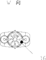
Fig. 2 is that the W of knob among Fig. 1 is to structural representation.
Embodiment
Below by embodiment, and in conjunction with the accompanying drawings, the technical solution of the utility model is described further.
Embodiment.See Fig. 1 and Fig. 2, a kind of vibration damper that has nine grades of adjusting mechanisms of the utility model, comprise clutch release slave cylinder 13 and place its outer surge drum 14, be provided with piston rod 20 in clutch release slave cylinder 13 central interior, be provided with piston valve assembly 5 in the lower end of piston rod 20, the upper end of this piston rod 20 has guider 1, and guider 1 is provided with the pilot hole 2 that return tube 3 and clutch release slave cylinder 13 chambers are communicated, and air bag 12 is housed on surge drum 14; In clutch release slave cylinder 13, surge drum 14 and return tube 3, all filled with shock absorber fluid; Described piston valve assembly 5 upper ends have circulation valve block 4, and have compensation valve block 6 in the upper end of compression valve assembly 7; Described clutch release slave cylinder 13 bottoms are connected with compression valve assembly 7, described surge drum 14 bottoms are connected with base 11, be provided with REG Regulator Assembly 19 in the middle of the described base 11, this REG Regulator Assembly 19 comprises knob 16 and connected spool 15, be provided with link 23 between this knob 16 and the spool, described spool 15 outsides are connected base 11 by spring 10 with copper catch 9.
Wherein, described base 11 is provided with sealing gasket 17 with the joint of REG Regulator Assembly 19, is provided with O type circle 18 between spool 15 and base 11.Guarantee that the junction between REG Regulator Assembly 19 and the base 11 can leakage of oil.And be provided with bottom valve hole 8 at base 11 near copper catch end, this bottom valve hole 8 communicates with compression valve assembly 7.Simultaneously between described spool 15 ends and base 11, be provided with metal catch 9.
The working principle of this vibration damper is as follows:
When vibration damper during at the compression movement state, at this moment the compensation valve block 6 in the compression valve assembly 7 is closed.And fluid is closed by the passage that compression valve assembly 7 flows downward, and along with when compression piston rod 20 the shock absorber oil that enters just be forced upwardly motion by cavity of resorption 22, will make the circulation valve block 4 in the piston valve assembly 5 be opened, shock absorber oil just enters epicoele 21 and enters into return tube 3 through the pilot hole 2 in the guider 1 like this, shock absorber oil will be washed the copper catch 9 that is supported by spring 10 open under the effect of pressure, enter into surge drum 14 through bottom valve hole 8 then, at this moment air bag 12 will be in compressed state.
When vibration damper during at the extensional motion state, at this moment the circulation valve block 4 in the piston valve assembly 5 just is in closed state, and at this moment the oil in vibration damper clutch release slave cylinder 13 epicoeles 21 just is forced upwardly motion; At this moment shock absorber oil just enters into return tube 3 by the pilot hole in the guider 12, open by the copper catch 9 that spring 10 supports by compressing then, owing to the move upward valve block 4 that circulates of piston rod 20 is again a closed state, so will produce negative pressure at cavity of resorption 22, at this moment the compensation valve block 6 in the compression valve assembly 7 will be opened; Shock absorber oil will enter into the cavity of resorption 22 of clutch release slave cylinder 13, and the air bag 12 in the surge drum 14 also can return to initial conditions.
Nine grades of adjustings are achieved as follows: when adjusting knob 16 being adjusted to 1-9 grades of different gears.Knob 16 will make spool 15 travel forward by the conduction of the screw thread on the link 23 button power, and at this moment spring 10 will produce the power of precompressed; And the pressure that the copper catch 9 that it supports bears will strengthen.Shock absorber oil needed power when opening copper catch 9 also just strengthens like this, so the damping force of vibration damper will increase; Otherwise the damping force of vibration damper will reduce, and the damping force that so just can make vibration damper is on different road surfaces, or can both reach best effect when bearing different weight.
It is apparent to one skilled in the art that the utility model can be changed into multiple mode, and such change is not thought and broken away from scope of the present utility model.What all were such will be included within the scope of this claim the conspicuous modification of described those skilled in the art.
Claims (5)
1, a kind of vibration damper that has nine grades of adjusting mechanisms, comprise clutch release slave cylinder (13) and place its outer surge drum (14), be provided with piston rod (20) in clutch release slave cylinder (13) central interior, be provided with piston valve assembly (5) in the lower end of piston rod (20), described clutch release slave cylinder (13) bottom is connected with compression valve assembly (7), surge drum (14) bottom is connected with base (11), it is characterized in that being provided with REG Regulator Assembly (19) in the middle of the described base (11).
2, the vibration damper that has nine grades of adjusting mechanisms according to claim 1, it is characterized in that described REG Regulator Assembly (19) comprises knob (16) and connected spool (15), be provided with link (23) between this knob (16) and the spool, described spool (15) outside is connected base (11) by spring (10) with copper catch (9).
3, the vibration damper that has nine grades of adjusting mechanisms according to claim 2, it is characterized in that the described base (11) and the joint of REG Regulator Assembly (19) are provided with sealing gasket (17), are provided with O type circle (18) and seal contact between spool (15) and base (11).
4, according to claim 1 or the 2 or 3 described vibration dampers that have nine grades of adjusting mechanisms, it is characterized in that described base (11) is provided with bottom valve hole (8) near the catch end, this bottom valve hole (8) communicates with compression valve assembly (7).
5,, it is characterized in that being provided with copper catch (9) between described spool (15) end and the base (11) according to claim 2 or the 3 described vibration dampers that have nine grades of adjusting mechanisms.
Priority Applications (1)
| Application Number | Priority Date | Filing Date | Title |
|---|---|---|---|
| CNU2008200871197U CN201202762Y (en) | 2008-05-12 | 2008-05-12 | Bumper absorber with nine-shift adjustable mechanism |
Applications Claiming Priority (1)
| Application Number | Priority Date | Filing Date | Title |
|---|---|---|---|
| CNU2008200871197U CN201202762Y (en) | 2008-05-12 | 2008-05-12 | Bumper absorber with nine-shift adjustable mechanism |
Publications (1)
| Publication Number | Publication Date |
|---|---|
| CN201202762Y true CN201202762Y (en) | 2009-03-04 |
Family
ID=40425075
Family Applications (1)
| Application Number | Title | Priority Date | Filing Date |
|---|---|---|---|
| CNU2008200871197U Expired - Lifetime CN201202762Y (en) | 2008-05-12 | 2008-05-12 | Bumper absorber with nine-shift adjustable mechanism |
Country Status (1)
| Country | Link |
|---|---|
| CN (1) | CN201202762Y (en) |
Cited By (4)
| Publication number | Priority date | Publication date | Assignee | Title |
|---|---|---|---|---|
| CN104214264A (en) * | 2014-08-01 | 2014-12-17 | 安徽工程大学 | Damping/stiffness-adjustable hydraulic damper of multidimensional vibration damping platform |
| CN104235257A (en) * | 2014-09-09 | 2014-12-24 | 芜湖弘祥汽车减振器工业有限公司 | Flow regulator and shock absorber |
| CN104405814A (en) * | 2014-11-21 | 2015-03-11 | 重庆隆鑫发动机有限公司 | Adjustment assembly for shock absorbing damping |
| CN106352005A (en) * | 2016-11-25 | 2017-01-25 | 中航飞机起落架有限责任公司 | Oil and gas separation buffer and exhaust method thereof |
-
2008
- 2008-05-12 CN CNU2008200871197U patent/CN201202762Y/en not_active Expired - Lifetime
Cited By (5)
| Publication number | Priority date | Publication date | Assignee | Title |
|---|---|---|---|---|
| CN104214264A (en) * | 2014-08-01 | 2014-12-17 | 安徽工程大学 | Damping/stiffness-adjustable hydraulic damper of multidimensional vibration damping platform |
| CN104214264B (en) * | 2014-08-01 | 2017-01-11 | 安徽工程大学 | Damping/stiffness-adjustable hydraulic damper of multidimensional vibration damping platform |
| CN104235257A (en) * | 2014-09-09 | 2014-12-24 | 芜湖弘祥汽车减振器工业有限公司 | Flow regulator and shock absorber |
| CN104405814A (en) * | 2014-11-21 | 2015-03-11 | 重庆隆鑫发动机有限公司 | Adjustment assembly for shock absorbing damping |
| CN106352005A (en) * | 2016-11-25 | 2017-01-25 | 中航飞机起落架有限责任公司 | Oil and gas separation buffer and exhaust method thereof |
Similar Documents
| Publication | Publication Date | Title |
|---|---|---|
| CN2811665Y (en) | Single-chamber oil-gas separation type oil-gas spring with nonlinear characteristics | |
| CN103802626B (en) | Vehicle suspension system | |
| CN104455177A (en) | Automobile active self-adaption type shock absorber | |
| CN202914612U (en) | Push rod type variable rigidity adjustable oil gas spring | |
| CN105443636A (en) | Mixed communication type oil-gas shock attenuation device | |
| CN103821868B (en) | There is the vibration damper of bilateral throttle valve and pneumatic spring | |
| CN201202762Y (en) | Bumper absorber with nine-shift adjustable mechanism | |
| CN212272918U (en) | Double-spring shock absorber | |
| CN203248591U (en) | Vibration damper for heavy-loaded truck | |
| CN203743286U (en) | Shock absorber provided with double-pass throttle valves and air spring | |
| CN103775555B (en) | The stepless adjustable hydro-pneumatic spring of push rod rigidity | |
| CN204153042U (en) | Automobile absorber | |
| CN105485233A (en) | Oil-gas damper | |
| CN102358131A (en) | Semi-active suspension frame for tractor | |
| CN102996696A (en) | Rear suspension oil cylinder for heavy-duty industrial mining vehicle | |
| CN202955172U (en) | Shock absorber | |
| CN201763878U (en) | Single-barrel shock absorber | |
| CN213870882U (en) | Compression buffer structure of shock absorber | |
| CN211343836U (en) | Hydraulic shock absorber for electric vehicle | |
| CN107654558A (en) | A kind of vehicle shock absorber | |
| CN107989947B (en) | Multi-piston damping adjustable shock absorber mechanism | |
| CN201232727Y (en) | Hydraulic buffer vibration-damper | |
| CN207539249U (en) | A kind of vehicle shock absorber | |
| CN206206486U (en) | A kind of rearmounted damping of automobile cab | |
| CN103267082A (en) | Double-cylinder high-pressure magnetorheological shock absorber |
Legal Events
| Date | Code | Title | Description |
|---|---|---|---|
| C14 | Grant of patent or utility model | ||
| GR01 | Patent grant | ||
| C56 | Change in the name or address of the patentee |
Owner name: ADD ZHEJIANG INDUSTRIAL CO., LTD. Free format text: FORMER NAME: ZHEJIANG ZHENGYU INDUSTRY CO., LTD. |
|
| CP01 | Change in the name or title of a patent holder |
Address after: 317600 Zhejiang province Yuhuan County Zhugang Shuanggang Road No. 38-88 Patentee after: Zhejiang Zhengyu Industry Co.,Ltd. Address before: 317600 Zhejiang province Yuhuan County Zhugang Shuanggang Road No. 38-88 Patentee before: Zhejiang Zhengyu Industry Co., Ltd. |
|
| CX01 | Expiry of patent term | ||
| CX01 | Expiry of patent term |
Granted publication date: 20090304 |