CN201193412Y - Multi-rod connecting piece of tent top - Google Patents
Multi-rod connecting piece of tent top Download PDFInfo
- Publication number
- CN201193412Y CN201193412Y CNU2008201022328U CN200820102232U CN201193412Y CN 201193412 Y CN201193412 Y CN 201193412Y CN U2008201022328 U CNU2008201022328 U CN U2008201022328U CN 200820102232 U CN200820102232 U CN 200820102232U CN 201193412 Y CN201193412 Y CN 201193412Y
- Authority
- CN
- China
- Prior art keywords
- bar
- joint element
- tent
- lower cover
- loam cake
- Prior art date
- Legal status (The legal status is an assumption and is not a legal conclusion. Google has not performed a legal analysis and makes no representation as to the accuracy of the status listed.)
- Expired - Fee Related
Links
Images


Abstract
The utility model discloses a multi-rod connector at the top of a tent, comprising an upper cover, a lower cover and a plurality of rotary parts. The opposing end faces of the upper and lower covers are respectively provided with opposing annular grooves which are in involution to form annular slot after connecting the both thereof; one end of the rotary part is provided with a pin joint seat and the other end thereof is provided with a T-shaped fixture block which is slidably blocked in the annular slot; the rotary part of the multi-rod connector with a pin joint seat is applicable to tents with a plurality of hack levers and variable in any angle as a result of separating from the main body part formed by the upper and lower covers and sliding in the annular slot formed between the upper and lower covers, thereby being capable of saving development cost and time.
Description
Technical field
The utility model relates to a kind of accessory of tent, refers to a kind of many joint element for bar of tent top especially.
Background technology
In the prior art, the top structure of tent bracket as shown in Figure 1, it comprises some hack levers 1, the inner of each root hack lever 1 then is articulated in more than one on the joint element for bar 2 jointly.Form some pin joint seats 21 on these many joint element for bar 2, in order to articulate described hack lever 1.And existing tent can be divided into four bars, five bars, six bars, eight bars or ten rod tents or the like according to the quantity of hack lever, can be divided into square, rectangle, hexagon, octagon tent etc. again according to the angle difference of each hack lever.But each pin joint seat 21 of existing many joint element for bar 2 is integrated, and this just means that a kind of many joint element for bar 2 of structure can only be applicable to a kind of tent of structure, so applicability is relatively poor, and development cost is higher.
In addition, for increasing the support steadiness of each hack lever 1, also be supported with an auxilliary support bar 3 below every hack lever 1, the inner of each auxilliary support bar 3 also is articulated on another many joint element for bar 4 jointly.These many joint element for bar 4 are similar with above-mentioned many joint element for bar 2, and also one-body molded on it have some pin joint seats 41, in order to articulate auxilliary support bar 3, therefore also exists a kind of structure can only be suitable for a kind of shortcoming of tent.
The utility model content
The technical problem that the utility model institute desire solves is to provide a kind of many joint element for bar of tent top, and these many joint element for bar are applicable to having the tent that various radical hack levers and angle change.
For reaching above-mentioned technical problem, technical solution of the present utility model is:
A kind of many joint element for bar of tent top, it comprises loam cake, lower cover and some revolving parts; The opposing end surface of this loam cake and lower cover is respectively equipped with relative annular groove, and after both connected, its annular groove was combined to form an annular slot; Described revolving part one end is provided with pin joint seat, and the other end then is provided with T shape fixture block, and this T shape draw-in groove cunning is stuck in the above-mentioned annular slot.
Be spirally connected mutually by on both, internal and external threads being set respectively between described loam cake and the lower cover.
Adopt screw to interconnect between described loam cake and the lower cover.
Mode with clamping between described loam cake and the lower cover makes both be connected.
After adopting such scheme, because many joint element for bar described in the utility model separate pin joint seat with the main part that upper and lower covers constitutes, therefore the revolving part of respective numbers can be set according to the hack lever radical of actual tent, and the many joint element for bar that make a kind of structure are promptly applicable to the tent of multiple bar number.In addition, slide arbitrarily in the annular slot that described revolving part can form between upper and lower covers by its T shape fixture block, the tent that has various angles so upon deployment, nature draws the position that moves on to respective angles with each revolving part under the drive of tarpaulin, thereby makes the tent of described many joint element for bar applicable to multiple angles.By the improvement of said structure, only need a grip assembly, promptly can be assembled into and have various bar numbers and tent at any angle, therefore can save greatly development cost and time.
Description of drawings
Fig. 1 is the top structure schematic diagram of existing tent bracket;
Fig. 2 is the top structure schematic diagram of tent bracket described in the utility model;
Fig. 3 is the top structure sectional view of tent bracket described in the utility model;
Fig. 4 is the schematic diagram after the upper and lower covers combination described in the utility model;
Fig. 5 is the schematic perspective view of revolving part described in the utility model.
The specific embodiment
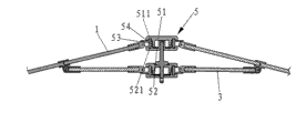
Shown in Fig. 2,3, the top structure of tent bracket described in the utility model mainly comprises some hack levers 1, and the inner of each root hack lever 1 then is articulated in more than one on the joint element for bar 5 jointly.For increasing the support steadiness of each hack lever 1, below every hack lever 1, also be supported with an auxilliary support bar 3, the inner of each auxilliary support bar 3 also is articulated on another many joint element for bar 6 jointly.Wherein:
Described many joint element for bar 5 comprise loam cake 51, lower cover 52 and some revolving parts 53.As shown in Figure 4, the opposing end surface of this loam cake 51 and lower cover 52 is respectively equipped with relative annular groove 511,521, and after both connections, its annular groove 511,521 is combined to form an annular slot 54.Again as shown in Figure 5, described revolving part 53 1 ends are provided with pin joint seat 531 in order to articulate with described hack lever 1, and the other end then is provided with T shape fixture block 532, and this T shape draw-in groove 532 can be slided and be stuck in the above-mentioned annular slot 54.
And the structure similar of the structure of described another many joint element for bar 6 and many joint element for bar 5, so repeat no more.
Many joint element for bar 5 of said structure, because pin joint seat 531 is separated with the main part that upper and lower covers 51,52 constitutes, therefore the revolving part 53 of respective numbers can be set according to the radical of actual tent hack lever 1, and the many joint element for bar that make a kind of structure are promptly applicable to the tent of multiple bar number.In addition, any slip in the annular slot 54 that described revolving part 53 can form between upper and lower covers 51,52 by its T shape fixture block 532, the tent that has various angles so upon deployment, nature draws the position that moves on to respective angles with each revolving part 53 under the drive of tarpaulin, thereby makes the tent of described many joint element for bar applicable to multiple angles.
Can interconnect by multiple structure between described loam cake 51 and the lower cover 52.For example shown in Figure 4, by being set on both respectively, internal and external threads is spirally connected then between this loam cake 51 and the lower cover 52.The utility model also can adopt screw that both are linked together, and perhaps the mode with clamping makes both connect.
Claims (4)
1. many joint element for bar of a tent top, it is characterized in that: it comprises loam cake, lower cover and some revolving parts; The opposing end surface of this loam cake and lower cover is respectively equipped with relative annular groove, and after both connected, its annular groove was combined to form an annular slot; Described revolving part one end is provided with pin joint seat, and the other end then is provided with T shape fixture block, and this T shape draw-in groove cunning is stuck in the above-mentioned annular slot.
2. many joint element for bar of tent top according to claim 1 is characterized in that: be spirally connected mutually by on both internal and external threads being set respectively between described loam cake and the lower cover.
3. many joint element for bar of tent top according to claim 1 is characterized in that: adopt screw to interconnect between described loam cake and the lower cover.
4. many joint element for bar of tent top according to claim 1 is characterized in that: the mode with clamping between described loam cake and the lower cover makes both be connected.
Priority Applications (1)
| Application Number | Priority Date | Filing Date | Title |
|---|---|---|---|
| CNU2008201022328U CN201193412Y (en) | 2008-05-05 | 2008-05-05 | Multi-rod connecting piece of tent top |
Applications Claiming Priority (1)
| Application Number | Priority Date | Filing Date | Title |
|---|---|---|---|
| CNU2008201022328U CN201193412Y (en) | 2008-05-05 | 2008-05-05 | Multi-rod connecting piece of tent top |
Publications (1)
| Publication Number | Publication Date |
|---|---|
| CN201193412Y true CN201193412Y (en) | 2009-02-11 |
Family
ID=40392951
Family Applications (1)
| Application Number | Title | Priority Date | Filing Date |
|---|---|---|---|
| CNU2008201022328U Expired - Fee Related CN201193412Y (en) | 2008-05-05 | 2008-05-05 | Multi-rod connecting piece of tent top |
Country Status (1)
| Country | Link |
|---|---|
| CN (1) | CN201193412Y (en) |
Cited By (3)
| Publication number | Priority date | Publication date | Assignee | Title |
|---|---|---|---|---|
| WO2011094948A1 (en) * | 2010-02-05 | 2011-08-11 | 秋野地(厦门)露营用品有限公司 | Tent |
| WO2012100561A1 (en) * | 2011-01-28 | 2012-08-02 | 秋野地(厦门)露营用品有限公司 | Innovative tent top module |
| WO2016155172A1 (en) * | 2015-07-31 | 2016-10-06 | 秋野地(厦门)露营用品有限公司 | Tent top portion module structure having side pull cord |
-
2008
- 2008-05-05 CN CNU2008201022328U patent/CN201193412Y/en not_active Expired - Fee Related
Cited By (7)
| Publication number | Priority date | Publication date | Assignee | Title |
|---|---|---|---|---|
| WO2011094948A1 (en) * | 2010-02-05 | 2011-08-11 | 秋野地(厦门)露营用品有限公司 | Tent |
| CN102264989A (en) * | 2010-02-05 | 2011-11-30 | 秋野地(厦门)露营用品有限公司 | Tent |
| GB2491991A (en) * | 2010-02-05 | 2012-12-19 | Q Yield Outdoor Gear Ltd | Tent |
| CN102264989B (en) * | 2010-02-05 | 2013-05-01 | 秋野地(厦门)露营用品有限公司 | Tent |
| GB2491991B (en) * | 2010-02-05 | 2015-11-04 | Q Yield Outdoor Gear Ltd | Quick-pitch foldable tent structure. |
| WO2012100561A1 (en) * | 2011-01-28 | 2012-08-02 | 秋野地(厦门)露营用品有限公司 | Innovative tent top module |
| WO2016155172A1 (en) * | 2015-07-31 | 2016-10-06 | 秋野地(厦门)露营用品有限公司 | Tent top portion module structure having side pull cord |
Similar Documents
| Publication | Publication Date | Title |
|---|---|---|
| CN201193412Y (en) | Multi-rod connecting piece of tent top | |
| CN201372600Y (en) | Supporting structure for top part of tent | |
| US7758112B2 (en) | Foldable chair capable of being overlapped with other chairs vertically | |
| CN106050823A (en) | Advanced clip retainer | |
| CN204024196U (en) | A kind of tent with single-point lock | |
| AU2011257903B2 (en) | Portable clothes line | |
| CN205445113U (en) | Folding cool covering or awning on a car, boat, etc. frame and supporting mechanism thereof | |
| CN204071321U (en) | A kind of mattress fixture | |
| CN205640134U (en) | Telescopic link and telescopic selftimer | |
| CA2651164A1 (en) | An extendable shelf | |
| CN204199847U (en) | A kind of tent frame rod of bilayer top | |
| CN201193413Y (en) | Top module of tent support | |
| CN208236085U (en) | A kind of top hack lever of awning frame | |
| CN205617905U (en) | Cool covering or awning on a car, boat, etc. frame top hack lever and cool covering or awning on a car, boat, etc. frame | |
| CN206049758U (en) | A kind of children trolley of use time length | |
| CN201243695Y (en) | Loose-leaf form nest body umbrella frame structure | |
| CN205077982U (en) | Cool covering or awning on a car, boat, etc. frame of fast assembly and cool covering or awning on a car, boat, etc | |
| EP2026016A3 (en) | Roof tile | |
| CN2937599Y (en) | Multi-way jointing device | |
| CN219183494U (en) | Kitchen utensil spoon with telescopic handle | |
| EP1800990A3 (en) | Vehicle steering column shroud assembly | |
| CN2573593Y (en) | Collapsible window canopy | |
| EP1890070A3 (en) | Coupling assembly | |
| CN209547591U (en) | A kind of top angle connecting unit | |
| CN209776654U (en) | Turning joint for hood |
Legal Events
| Date | Code | Title | Description |
|---|---|---|---|
| C14 | Grant of patent or utility model | ||
| GR01 | Patent grant | ||
| C17 | Cessation of patent right | ||
| CF01 | Termination of patent right due to non-payment of annual fee |
Granted publication date: 20090211 Termination date: 20120505 |