CN201191663Y - Electric connector component - Google Patents

Electric connector component Download PDF

Info

Publication number
CN201191663Y
CN201191663Y CNU2008200320940U CN200820032094U CN201191663Y CN 201191663 Y CN201191663 Y CN 201191663Y CN U2008200320940 U CNU2008200320940 U CN U2008200320940U CN 200820032094 U CN200820032094 U CN 200820032094U CN 201191663 Y CN201191663 Y CN 201191663Y
Authority
CN
China
Prior art keywords
circuit board
printed circuit
electrical connector
pcb
metal
Prior art date
Legal status (The legal status is an assumption and is not a legal conclusion. Google has not performed a legal analysis and makes no representation as to the accuracy of the status listed.)
Expired - Fee Related
Application number
CNU2008200320940U
Other languages
Chinese (zh)
Inventor
叶昌旗
Current Assignee (The listed assignees may be inaccurate. Google has not performed a legal analysis and makes no representation or warranty as to the accuracy of the list.)
Foxconn Kunshan Computer Connector Co Ltd
Hon Hai Precision Industry Co Ltd
Original Assignee
Foxconn Kunshan Computer Connector Co Ltd
Hon Hai Precision Industry Co Ltd
Priority date (The priority date is an assumption and is not a legal conclusion. Google has not performed a legal analysis and makes no representation as to the accuracy of the date listed.)
Filing date
Publication date
Application filed by Foxconn Kunshan Computer Connector Co Ltd, Hon Hai Precision Industry Co Ltd filed Critical Foxconn Kunshan Computer Connector Co Ltd
Priority to CNU2008200320940U priority Critical patent/CN201191663Y/en
Application granted granted Critical
Publication of CN201191663Y publication Critical patent/CN201191663Y/en
Anticipated expiration legal-status Critical
Expired - Fee Related legal-status Critical Current

Links

Images

Landscapes

  • Coupling Device And Connection With Printed Circuit (AREA)

Abstract

本实用新型公开了一种电连接器组件,包括电连接器及金属背板,其中电连接器固定至印刷电路板的上方用于电性连接芯片模组与印刷电路板,金属背板组装至印刷电路板的下方,其与印刷电路板之间设置有绝缘塑胶片,其设有卡勾扣合至金属背板,使金属背板与印刷电路板之间达到良好的绝缘效果组装简单方便。

Figure 200820032094

The utility model discloses an electrical connector assembly, which comprises an electrical connector and a metal backboard, wherein the electrical connector is fixed above a printed circuit board for electrically connecting the chip module and the printed circuit board, and the metal backboard is assembled to the Below the printed circuit board, there is an insulating plastic sheet between it and the printed circuit board, which is provided with a hook to fasten to the metal backboard, so that a good insulation effect is achieved between the metal backboard and the printed circuit board, and the assembly is simple and convenient.

Figure 200820032094

Description

Electric coupler component
[technical field]
The utility model relates to a kind of electric coupler component, relates in particular to a kind of electric coupler component that is electrically connected to printed circuit board (PCB).
[background technology]
Because the present high speed data transfer of computer and because of job requirements, the operating time of computer is also more and more longer, and correspondingly the heat that central processing unit produced is increasing, is necessary to use heat abstractor, the heat that produces when leaving computer operation.When being installed on heat abstractor on the printed circuit board (PCB), because the weight that printed circuit board (PCB) is difficult to bear radiator generally increases the intensity that a backboard is strengthened printed circuit board (PCB).At present, industry backboard commonly used generally has two kinds, and a kind of is the backboard of using plastic shaping, another kind is with metal stamping formed backboard, and is simple with the backboard manufacturing of plastic shaping, and cost is lower, but in use its intensity is restricted, and can't reach required intensity sometimes.Be illustrated in figure 1 as a kind of existing electric coupler component 100 ', it comprises and is used to electrically connect electric connector 1 ' and the metal backing 4 ' of chip module 5 ' to printed circuit board (PCB) 3 '.Metal backing 4 ' has higher intensity, can satisfy the demand of intensity, but needs the insulation effect between assurance metal backing 4 ' and the printed circuit board (PCB) 3 '.At present, a kind of existing technology is by pasting a kind of soft insulating trip (not shown) at backboard 4 ' upper surface.
Yet this kind insulating trip does not have location feature, utilizes viscose glue to fit again, therefore paste easily askew, produce phenomenons such as fold and bubble, therefore comparatively difficult in the assembling.
Therefore, be necessary to design a kind of new electric coupler component to overcome above-mentioned shortcoming.
[utility model content]
The purpose of this utility model is to provide a kind of electric coupler component, can reach good insulation performance effect and easy to assembly between its metal backing and the printed circuit board (PCB).
For achieving the above object, the utility model adopts following technical scheme: a kind of electric coupler component, comprise electric connector and metal backing, wherein the electric connector top that is fixed to printed circuit board (PCB) is used to electrically connect chip module and printed circuit board (PCB), metal backing is assembled to the below of printed circuit board (PCB), be provided with the insulation sheet between itself and the printed circuit board (PCB), it is provided with trip and fastens to metal backing.
Compared to prior art, the insulation sheet can reach the good insulation performance effect in the utility model electric coupler component, and can fasten to metal backing by trip, easily assembling and inaccurate problem can not occur locating.
[description of drawings]
Fig. 1 is the three-dimensional exploded view of the electric coupler component relevant with the utility model.
Fig. 2 is the three-dimensional exploded view of the utility model electric coupler component.
Fig. 3 is the face upwarding stereogram of the insulation sheet of the utility model electric coupler component.
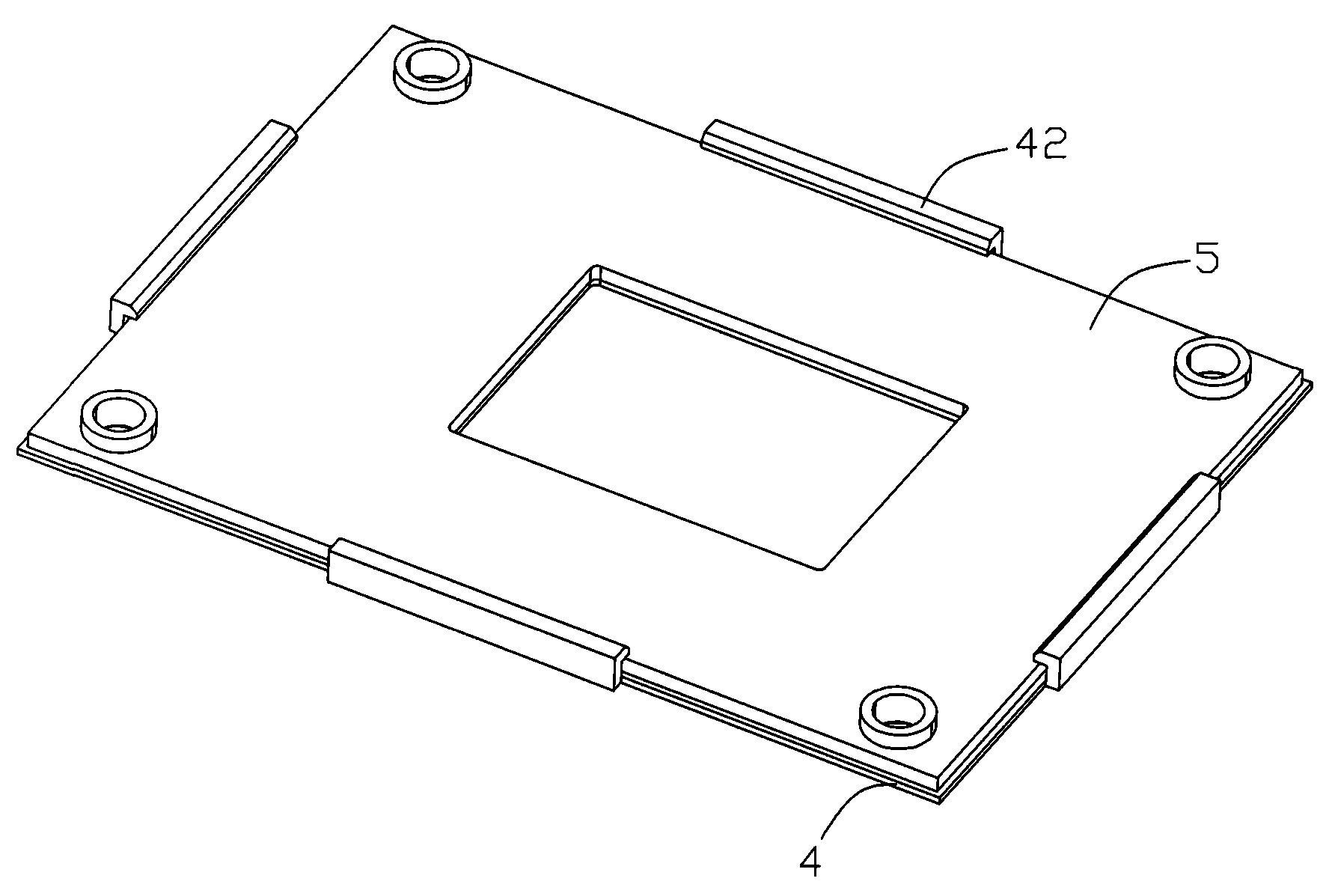
Fig. 4 is the insulation sheet of the utility model electric coupler component and the face upwarding stereogram after the backboard assembling.
[embodiment]
Shown in Fig. 2,3,4, the utility model electric coupler component 100 comprises electric connector 1, metal backing 5 and insulation sheet 4.
Electric connector 1 is installed in the top of printed circuit board (PCB) 3, is used to electrically connect chip module 6 to printed circuit board (PCB) 3, and it is provided with some installing holes 11, and correspondence is provided with some circular holes 31 on the printed circuit board (PCB) 3.
The plate-like structure that metal backing 5 forms for punching press, the below that is installed in printed circuit board (PCB) 3 is used to strengthen the intensity of printed circuit board (PCB) 3, and the circular hole 31 on its corresponding printed circuit board (PCB) 3 is provided with assembly hole 51.
Insulation sheet 4 is located between metal backing 5 and the printed circuit board (PCB) 4, it is for plate-like structure and be slightly larger than metal backing 5, trip 42 is extended on insulation sheet 4 four limits, in the present embodiment, insulation sheet 4 four limits are respectively extended a trip 42 and are fastened four limits to metal backing 5, please consult shown in Figure 3ly simultaneously, and trip 42 is provided with lead-in chamfered 421, when being assembled to metal backing 5, make assembling more convenient.Circular hole on the insulation sheet 4 corresponding printed circuit board (PCB)s 3 is provided with location hole 41.
The utility model is to pass through fixture, as screw 2, pass location hole 41 on installing hole 11 on the electric connector 1, the circular hole 31 on the printed circuit board (PCB) 3, the insulation sheet 4 and the assembly hole 51 on the metal backing 5, according to this electric connector 1, insulation sheet 4 and metal backing 5 firm be assembled to printed circuit board (PCB) 3.
The utility model emphasis structure is: an insulation sheet 4 is set between metal backing 5 and printed circuit board (PCB) 3, and it is provided with trip 42 and fastens to metal backing 5, makes and realizes good insulation performance effect and easy to assembly between metal backing 5 and the printed circuit board (PCB) 3.
Should be understood that, the above only is a kind of execution mode of the present utility model, it or not whole or unique execution mode, the variation of any equivalence that those of ordinary skills take technical solutions of the utility model by reading the utility model specification is claim of the present utility model and contains.

Claims (5)

1.一种电连接器组件,包括电连接器及金属背板;其中电连接器固定至印刷电路板的上方用于电性连接芯片模组至印刷电路板,金属背板固定至印刷电路板的下方;其特征在于:所述金属背板与印刷电路板之间设置有绝缘塑胶片,绝缘塑胶片设有卡勾扣合在金属背板上。1. An electrical connector assembly, comprising an electrical connector and a metal back plate; wherein the electrical connector is fixed to the top of the printed circuit board for electrically connecting the chip module to the printed circuit board, and the metal back plate is fixed to the printed circuit board It is characterized in that: an insulating plastic sheet is arranged between the metal backboard and the printed circuit board, and the insulating plastic sheet is provided with a hook to fasten on the metal backboard. 2.如权利要求1所述的电连接器组件,其特征在于:所述卡勾设置有引导金属背板组装的引导斜面。2. The electrical connector assembly according to claim 1, wherein the hook is provided with a guiding slope for guiding assembly of the metal backplane. 3.如权利要求1所述的电连接器组件,其特征在于:所述金属背板设置有组装孔。3. The electrical connector assembly according to claim 1, wherein the metal back plate is provided with an assembly hole. 4.如权利要求3所述的电连接器组件,其特征在于:所述绝缘塑胶片设有与所述组装孔相对应的定位孔。4. The electrical connector assembly according to claim 3, wherein the insulating plastic sheet is provided with a positioning hole corresponding to the assembly hole. 5.如权利要求4所述的电连接器组件,其特征在于:所述电连接器、绝缘塑胶片及金属背板通过固定装置如螺丝固定至印刷电路板。5 . The electrical connector assembly according to claim 4 , wherein the electrical connector, the insulating plastic sheet and the metal back plate are fixed to the printed circuit board by a fixing device such as a screw.
CNU2008200320940U 2008-03-11 2008-03-11 Electric connector component Expired - Fee Related CN201191663Y (en)

Priority Applications (1)

Application Number Priority Date Filing Date Title
CNU2008200320940U CN201191663Y (en) 2008-03-11 2008-03-11 Electric connector component

Applications Claiming Priority (1)

Application Number Priority Date Filing Date Title
CNU2008200320940U CN201191663Y (en) 2008-03-11 2008-03-11 Electric connector component

Publications (1)

Publication Number Publication Date
CN201191663Y true CN201191663Y (en) 2009-02-04

Family

ID=40335823

Family Applications (1)

Application Number Title Priority Date Filing Date
CNU2008200320940U Expired - Fee Related CN201191663Y (en) 2008-03-11 2008-03-11 Electric connector component

Country Status (1)

Country Link
CN (1) CN201191663Y (en)

Cited By (3)

* Cited by examiner, † Cited by third party
Publication number Priority date Publication date Assignee Title
WO2010096513A1 (en) * 2009-02-18 2010-08-26 Molex Incorporated Electrical connector assembly with back plate
CN102026517A (en) * 2009-09-16 2011-04-20 富准精密工业(深圳)有限公司 Back plate assembly and electronic device with same
CN107797048A (en) * 2017-11-14 2018-03-13 北京品驰医疗设备有限公司 Reliability test system and its printed circuit-board assembly

Cited By (4)

* Cited by examiner, † Cited by third party
Publication number Priority date Publication date Assignee Title
WO2010096513A1 (en) * 2009-02-18 2010-08-26 Molex Incorporated Electrical connector assembly with back plate
CN102026517A (en) * 2009-09-16 2011-04-20 富准精密工业(深圳)有限公司 Back plate assembly and electronic device with same
CN107797048A (en) * 2017-11-14 2018-03-13 北京品驰医疗设备有限公司 Reliability test system and its printed circuit-board assembly
CN107797048B (en) * 2017-11-14 2023-12-29 北京品驰医疗设备有限公司 Reliability test system and its printed circuit board assembly

Similar Documents

Publication Publication Date Title
CN203118477U (en) Solid-state hard disk
CN201178163Y (en) Electric connector assembly
CN201191663Y (en) Electric connector component
CN207321769U (en) A kind of high efficiency and heat radiation Universal machine cabinet based on conduction
CN206558668U (en) Clamp plate type antenna holder
CN203827668U (en) Metal frame for slot type acquisition case
CN204883529U (en) External card fixing frame
CN205491628U (en) a radiator
CN2901612Y (en) Connector for connecting PCB board
CN205811227U (en) DDR series memory module switching device
CN204836795U (en) Grafting circuit board
CN201654605U (en) host computer
CN210431491U (en) Mobile phone chip plug-in structure
CN202353929U (en) Flexible printed circuit
CN201252283Y (en) Electric connector component and backboard thereof
CN107196172A (en) A kind of forced connector precision positioning compression bonding apparatus
CN203880628U (en) Assembly structure of LED lamp tube and side cover
CN222655399U (en) Soft base plate of concatenation connection
CN206728363U (en) Pcb board with radiator structure
CN206225528U (en) A kind of plain antenna fixing device
CN221842739U (en) A convenient plug-in power circuit board fixed installation structure
CN201364971Y (en) Grounding strip and grounding strip device
CN207764514U (en) A kind of circle display module
CN215987137U (en) Computer display card with quick mounting structure
CN204578938U (en) The information-based storage circuit plate of a kind of assembly type

Legal Events

Date Code Title Description
C14 Grant of patent or utility model
GR01 Patent grant
CF01 Termination of patent right due to non-payment of annual fee

Granted publication date: 20090204

Termination date: 20170311

CF01 Termination of patent right due to non-payment of annual fee