CN201166364Y - gas burner - Google Patents
gas burner Download PDFInfo
- Publication number
- CN201166364Y CN201166364Y CNU200720015458XU CN200720015458U CN201166364Y CN 201166364 Y CN201166364 Y CN 201166364Y CN U200720015458X U CNU200720015458X U CN U200720015458XU CN 200720015458 U CN200720015458 U CN 200720015458U CN 201166364 Y CN201166364 Y CN 201166364Y
- Authority
- CN
- China
- Prior art keywords
- burner
- gas
- main
- duty
- air
- Prior art date
- Legal status (The legal status is an assumption and is not a legal conclusion. Google has not performed a legal analysis and makes no representation as to the accuracy of the status listed.)
- Expired - Fee Related
Links
- 238000002485 combustion reaction Methods 0.000 claims abstract description 28
- 239000000203 mixture Substances 0.000 claims description 16
- 238000002347 injection Methods 0.000 claims description 10
- 239000007924 injection Substances 0.000 claims description 10
- 238000010586 diagram Methods 0.000 description 4
- 238000010438 heat treatment Methods 0.000 description 2
- 238000000034 method Methods 0.000 description 2
- 230000009286 beneficial effect Effects 0.000 description 1
- 239000012141 concentrate Substances 0.000 description 1
- 238000009434 installation Methods 0.000 description 1
- 230000008092 positive effect Effects 0.000 description 1
- 239000000243 solution Substances 0.000 description 1
- 238000005496 tempering Methods 0.000 description 1
Images


Classifications
-
- Y—GENERAL TAGGING OF NEW TECHNOLOGICAL DEVELOPMENTS; GENERAL TAGGING OF CROSS-SECTIONAL TECHNOLOGIES SPANNING OVER SEVERAL SECTIONS OF THE IPC; TECHNICAL SUBJECTS COVERED BY FORMER USPC CROSS-REFERENCE ART COLLECTIONS [XRACs] AND DIGESTS
- Y02—TECHNOLOGIES OR APPLICATIONS FOR MITIGATION OR ADAPTATION AGAINST CLIMATE CHANGE
- Y02E—REDUCTION OF GREENHOUSE GAS [GHG] EMISSIONS, RELATED TO ENERGY GENERATION, TRANSMISSION OR DISTRIBUTION
- Y02E20/00—Combustion technologies with mitigation potential
- Y02E20/34—Indirect CO2mitigation, i.e. by acting on non CO2directly related matters of the process, e.g. pre-heating or heat recovery
Landscapes
- Pre-Mixing And Non-Premixing Gas Burner (AREA)
- Gas Burners (AREA)
Abstract
本实用新型提供的是燃气燃烧器。在底腔的上部连接有主燃气、空气混合气导管和主燃烧器外壳,外壳上安装有主燃烧器内环,其上设有燃烧孔,中心部位固定有值班燃烧器护罩并安装有值班燃烧器,主燃烧器内环与主燃烧器外壳之间形成主燃气、空气预热混合腔,主燃气、空气混合腔内安装有扰流器;值班燃烧器通过值班燃气、空气混合气导管与值班燃气进气管和值班空气进口相连通,在底腔的一侧安装有值班燃气进气管和主燃气进气管,其上设有主燃气喷出孔,主燃气喷出孔置于主燃气、空气混合腔内。本实用新型具有受外界干扰小、火焰高度低、温度高、燃烧充分、热利用率高、节能、安全的特点。适宜各种燃气器具燃烧获得热量使用。
The utility model provides a gas burner. The upper part of the bottom cavity is connected with the main gas, air mixed gas conduit and the main burner casing. The main burner inner ring is installed on the casing, and there are combustion holes on it. For the burner, the main gas and air preheating mixing cavity is formed between the inner ring of the main burner and the outer shell of the main burner, and a spoiler is installed in the mixing cavity of the main gas and air; The duty gas inlet pipe is connected with the duty air inlet. On one side of the bottom chamber, the duty gas inlet pipe and the main gas inlet pipe are installed. inside the mixing chamber. The utility model has the characteristics of little external interference, low flame height, high temperature, sufficient combustion, high heat utilization rate, energy saving and safety. It is suitable for burning various gas appliances to obtain heat.
Description
技术领域 technical field
本实用新型提供的是热工领域的燃烧供热器械,具体地说是燃气燃烧器。The utility model provides a combustion heating device in the field of thermal engineering, in particular a gas burner.
背景技术 Background technique
在本实用新型提出以前,有一种燃气燃烧器,其结构是:在底腔上通过燃气、空气混合管连接有炉头,在炉头的一侧设有值班燃烧器,在燃气、空气混合管的内部安装有燃气进气管,其上端开口为燃气喷出孔,燃气与空气呈同一方向供应给炉头进行燃烧。这种燃烧器存在的缺点是:1、燃气进气管的喷出孔与空气进气方向同向,混合性差,导致混合不均,影响燃烧性能,从而降低燃气燃烧效率;2、值班燃烧器安装在炉头的一侧,容易受到外界气流扰动,也容易熄火。再点燃炉头时还需要重新点燃值班燃烧器,操作麻烦,安全性差;3、炉头的内环环壁上所设的燃烧孔为垂直与环壁的直孔,燃焰容易漂移,火力不容易集中,火焰高度高,燃烧温度低,导致热效率低。4、容易产生回火,导致供气及供风设备的损坏,也容易引起安全事故。Before the utility model was proposed, there was a kind of gas burner, its structure was: on the bottom cavity, a burner was connected through a gas and air mixing tube, a burner on duty was arranged on one side of the burner, and the gas and air mixing tube A gas inlet pipe is installed inside the furnace, and its upper end is opened as a gas injection hole, and the gas and air are supplied to the burner in the same direction for combustion. The disadvantages of this kind of burner are: 1. The ejection hole of the gas inlet pipe is in the same direction as the air inlet direction, and the mixing property is poor, resulting in uneven mixing, which affects the combustion performance, thereby reducing the gas combustion efficiency; 2. The on-duty burner installation On the side of the burner, it is easy to be disturbed by the external airflow, and it is also easy to turn off the flame. Also need to relight the burner on duty when relighting the burner head again, troublesome operation, poor safety; It is easy to concentrate, the flame height is high, and the combustion temperature is low, resulting in low thermal efficiency. 4. Tempering is easy to occur, resulting in damage to air supply and air supply equipment, and also easy to cause safety accidents.
发明内容 Contents of the invention
为了克服现有燃气燃烧器的缺点,本实用新型提供了一种新型的燃气燃烧器。该燃烧器主要通过在燃气、空气混合腔内增设扰流器和改变燃气喷出孔的角度设计及值班燃烧器位置来实现燃气的充分燃烧、提高火焰温度,提高安全性及减少对燃烧部件的损害的技术问题。In order to overcome the shortcomings of the existing gas burner, the utility model provides a novel gas burner. The burner mainly achieves full combustion of gas, increases flame temperature, improves safety and reduces damage to combustion parts by adding a spoiler in the gas and air mixing chamber and changing the angle design of the gas injection hole and the position of the on-duty burner. Damaged technical issues.
本实用新型解决技术问题的方案是:在底腔的一侧设有进风口,在底腔上部连接有主燃气、空气混合气导管和主燃烧器外壳,在主燃烧器外壳与主燃烧器内环配合环口内安装有主燃烧器内环,主燃烧器内环环壁上设有若干个燃烧孔,中心部位固定有值班燃烧器护罩,在其内平面的环壁上通过值班燃烧器紧固器安装有值班燃烧器,主燃烧器内环与主燃烧器外壳之间形成主燃气、空气预热混合腔并与主燃气、空气混合腔通过扰流器相连通;The solution of the utility model to solve the technical problem is: an air inlet is provided on one side of the bottom cavity, and the main gas, air mixture conduit and the main burner casing are connected on the upper part of the bottom cavity, and the main burner casing and the main burner The inner ring of the main burner is installed in the matching ring mouth of the ring. Several combustion holes are arranged on the ring wall of the inner ring of the main burner. The on-duty burner is installed in the solidifier, and the main gas and air preheating mixing chamber is formed between the inner ring of the main burner and the outer shell of the main burner, and is connected with the main gas and air mixing chamber through a spoiler;
值班燃烧器通过值班燃气、空气混合气导管与值班燃气进气管和值班空气进口相连通,值班燃气进气管安装在底腔的一侧;The on-duty burner is connected with the on-duty gas inlet pipe and the on-duty air inlet through the on-duty gas and air mixture ducts, and the on-duty gas inlet pipe is installed on one side of the bottom cavity;
设在燃烧器内环环壁上的燃烧孔在与环壁垂直方向可排列3排,从上到下的水平角度分别是20°、25°和5°,孔与圆心连线夹角分别是:15°、15°和0°。The combustion holes set on the inner ring wall of the burner can be arranged in three rows in the vertical direction to the ring wall, the horizontal angles from top to bottom are 20°, 25° and 5° respectively, and the angles between the holes and the center of the circle are respectively : 15°, 15° and 0°.
在底腔一侧还安装有主燃气进气管,其上端横向设有若干个主燃气喷出孔,主燃气喷出孔置于主燃气、空气混合腔内。A main gas inlet pipe is also installed on one side of the bottom cavity, and several main gas injection holes are horizontally arranged on its upper end, and the main gas injection holes are placed in the main gas and air mixing chamber.
在主燃烧器内环的环壁上所设的燃烧孔与底平面夹角a在0~30°之间,与圆心连线夹角b在0~30°之间。The included angle a between the combustion hole and the bottom plane on the ring wall of the inner ring of the main burner is between 0° and 30°, and the included angle b between the line connecting the center of the circle and the center of the circle is between 0° and 30°.
在扰流器的中心设有值班燃气、空气混合气导管孔,在其外周设有若干放射形倾斜排列的叶板,在叶板之间形成过气腔。In the center of the spoiler, there are duty gas and air mixture duct holes, and a number of blades arranged radially and obliquely are arranged on the outer periphery of the spoiler, and an air passage cavity is formed between the blades.
积极效果是:1、由于在主进气管上设有横置的主燃气喷出孔,有利于燃气与空气的充分混合;2、由于值班空气进口设在值班燃气进气管的下部并置于在底腔内,有利于新鲜空气的进入与混合;3、由于在主燃气、空气混合腔内安装有扰流器,可以使燃气与空气的混合气进一步分散与混合;4、由于在主燃烧器外壳和主燃烧器内环之间设有主燃气、空气预热混合腔,有利于燃气、空气混合器的预热与充分燃烧;5、由于值班燃烧器设在主燃烧器内环中间并在其外侧设有值班燃烧器护罩,可以保证其燃烧不受气流扰动的干扰,不易熄火,保证其安全性,与设置在外侧相比使用寿命长并防止烧损;6、由于燃烧孔设置具有角度,可以实现火焰的旋转与重叠,从而降低火焰高度,提高火焰温度并防止烧损燃烧器内环,提高使用寿命。所以本实用新型具有受外界干扰小、火焰高度低、温度高、燃烧充分、热利用率高、节能、安全的特点。适宜各种燃气器具燃烧获得热量使用。The positive effects are: 1. Since the main gas inlet pipe is provided with a horizontal main gas injection hole, it is conducive to the full mixing of gas and air; 2. Since the duty air inlet is located at the lower part of the duty gas inlet pipe and placed The bottom chamber is conducive to the entry and mixing of fresh air; 3. Due to the turbulence installed in the main gas and air mixing chamber, the mixture of gas and air can be further dispersed and mixed; 4. Since the main burner There is a main gas and air preheating mixing chamber between the shell and the inner ring of the main burner, which is beneficial to the preheating and full combustion of the gas and air mixer; 5. Since the on-duty burner is located in the middle of the inner ring of the main burner and There is a burner guard on duty on the outside, which can ensure that its combustion will not be disturbed by air flow disturbance, and it is not easy to extinguish the flame to ensure its safety. Compared with the setting on the outside, it has a longer service life and prevents burnout; The angle can realize the rotation and overlap of the flame, thereby reducing the height of the flame, increasing the temperature of the flame and preventing the inner ring of the burner from being burned, and improving the service life. Therefore, the utility model has the characteristics of less external interference, low flame height, high temperature, sufficient combustion, high heat utilization rate, energy saving and safety. It is suitable for burning various gas appliances to obtain heat.
附图说明 Description of drawings
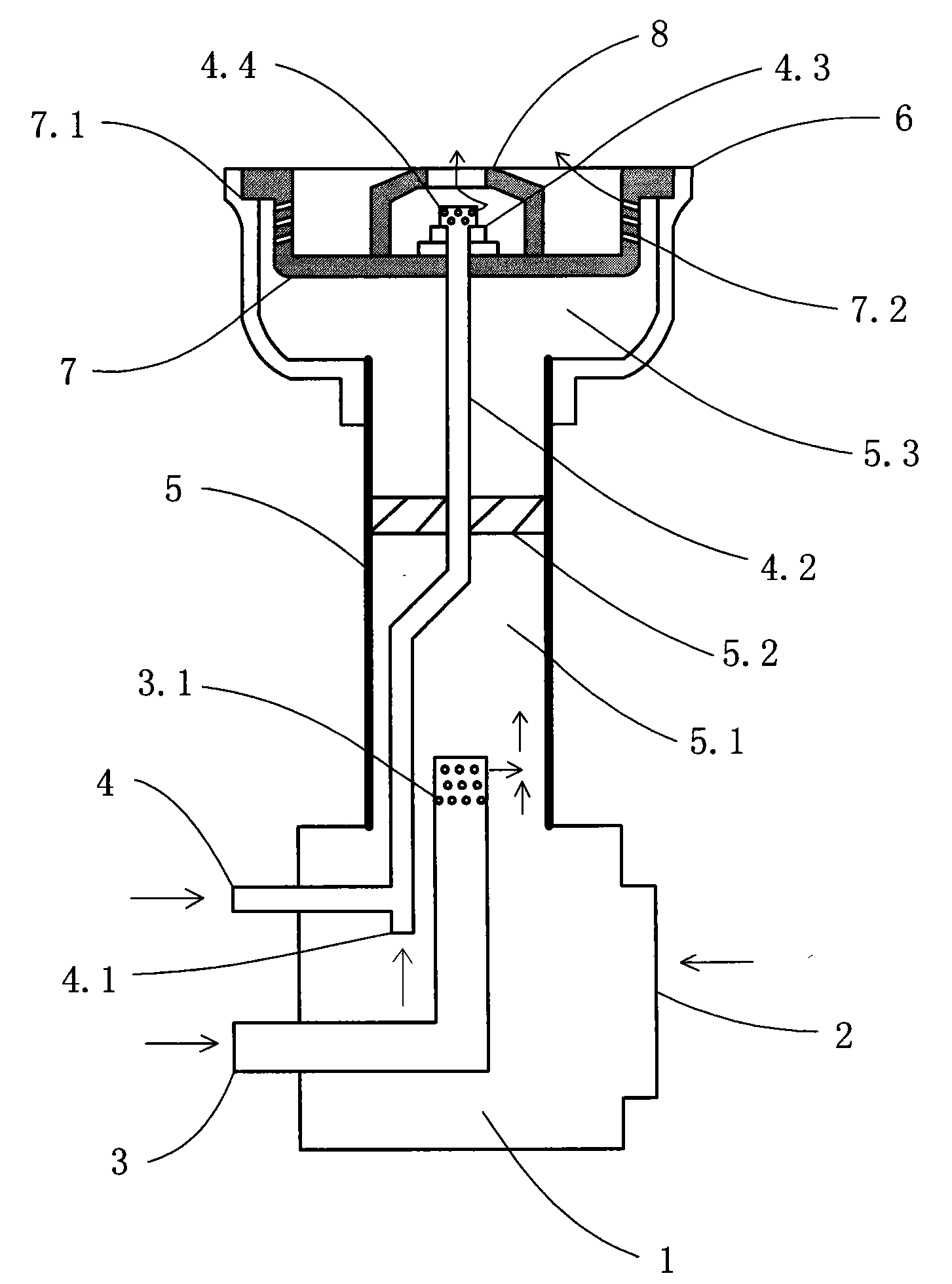
图1为本实用新型燃烧器结构图Fig. 1 is the structural diagram of the utility model burner
图2为本实用新型燃烧孔底平面夹角状态图Fig. 2 is the angle state diagram of the bottom plane of the combustion hole of the present invention
图3为本实用新型燃烧孔圆心连线夹角状态图Fig. 3 is a state diagram of the included angle between the lines connecting the centers of the combustion holes of the utility model
图4为本实用新型扰流器示意图Figure 4 is a schematic diagram of the utility model spoiler
图中,1.底腔,2.进风口,3.主燃气进气管,3.1.主燃气喷出孔,4.值班燃气进气管,4.1.值班空气进口,4.2.值班燃气、空气混合气导管,4.3.值班燃烧器紧固器,4.4.值班燃烧器,5.主燃气、空气混合气导管,5.1.主燃气、空气混合腔,5.2.扰流器,5.2.1.叶板,5.2.2.过气腔,5.2.3.值班燃气、空气混合气导管孔,5.3.主燃气、空气预热混合腔,6.主燃烧器外壳,7.主燃烧器内环,7.1.主燃烧器外壳与主燃烧器内环配合环口,7.2.燃烧孔,8.值班燃烧器护罩。In the figure, 1. Bottom cavity, 2. Air inlet, 3. Main gas inlet pipe, 3.1. Main gas outlet hole, 4. Duty gas inlet pipe, 4.1. Duty air inlet, 4.2. Duty gas, air mixture duct , 4.3. On-duty burner fastener, 4.4. On-duty burner, 5. Main gas and air mixture duct, 5.1. Main gas and air mixing chamber, 5.2. Spoiler, 5.2.1. Blade plate, 5.2. 2. Passing gas chamber, 5.2.3. Duty gas, air mixture duct hole, 5.3. Main gas, air preheating mixing chamber, 6. Main burner shell, 7. Main burner inner ring, 7.1. Main burner The outer shell matches the inner ring of the main burner, 7.2. The combustion hole, 8. The guard of the burner on duty.
具体实施方式 Detailed ways
据图1所示,在底腔1的一侧设有进风口2,在底腔上部连接有主燃气、空气混合气导管5和主燃烧器外壳6,在主燃烧器外壳与主燃烧器内环配合环口7.1内安装有主燃烧器内环7,主燃烧器内环环壁上设有若干个燃烧孔7.2,中心部位固定有值班燃烧器护罩8,在其内平面的环壁上通过值班燃烧器紧固器4.3安装有值班燃烧器4.4,主燃烧器内环与主燃烧器外壳之间形成主燃气、空气预热混合腔5.3并与主燃气、空气混合腔5.1通过扰流器5.2相连通;As shown in Figure 1, an
值班燃烧器通过值班燃气、空气混合气导管4.2与值班燃气进气管4和值班空气进口4.1相连通,值班燃气进气管安装在底腔的一侧;The on-duty burner communicates with the on-duty
设在燃烧器内环环壁上的燃烧孔在与环壁垂直方向可排列3排,从上到下的水平角度分别是20°、25°和5°,孔与圆心连线夹角分别是:15°、15°和0°。The combustion holes on the inner ring wall of the burner can be arranged in three rows in the vertical direction to the ring wall, the horizontal angles from top to bottom are 20°, 25° and 5° respectively, and the angles between the holes and the center of the circle are respectively : 15°, 15° and 0°.
在底腔一侧还安装有主燃气进气管3,其上端横向设有若干个主燃气喷出孔3.1,主燃气喷出孔置于主燃气、空气混合腔5.1内。One side of the bottom chamber is also equipped with a main
据图2和图3所示,在主燃烧器内环7的环壁上所设的燃烧孔7.2与底平面夹角a在0~30°之间,与圆心连线夹角b在0~30°之间。As shown in Figure 2 and Figure 3, the angle a between the combustion hole 7.2 and the bottom plane set on the ring wall of the
据图4所示,在扰流器5.2的中心设有值班燃气、空气混合气导管孔5.2.3,在其外周设有若干放射形倾斜排列的叶板5.2.1,在叶板之间形成过气腔5.2.2。As shown in Figure 4, the center of the spoiler 5.2 is provided with duty gas and air mixture duct holes 5.2.3, and a number of blades 5.2.1 arranged radially and obliquely are arranged on its outer periphery, forming 5.2.2 over the gas cavity.
本实用新型的工作过程Working process of the utility model
进风口接于送风机上,主燃气进气管与值班燃气进气管接于燃气源上。The air inlet is connected to the blower, and the main gas inlet pipe and the on-duty gas inlet pipe are connected to the gas source.
打开送风机向底腔内送入空气,接通值班燃气进气管,点燃值班燃烧器,然后接通主燃气进气管,燃气通过主燃气喷出孔横向与空气接触混合形成燃气、空气混合气,燃气、空气混合气通过扰流器进一步混合后到达主燃气、空气预热混合腔进行预热再混合,然后通过具有设定角度的燃烧孔喷出,与值班燃烧器火焰相遇点燃形成高温燃焰用于加热,燃焰以抛物线螺旋叠加方式形成高温区。Turn on the blower to send air into the bottom cavity, connect the gas inlet pipe on duty, ignite the burner on duty, and then connect the main gas inlet pipe, and the gas will contact and mix with the air horizontally through the main gas injection hole to form a gas-air mixture. The air mixture is further mixed through the spoiler and then reaches the main gas and air preheating mixing chamber for preheating and remixing, and then it is sprayed out through the combustion hole with a set angle, meets and ignites with the flame of the on-duty burner to form a high-temperature combustion flame. During heating, the combustion flame forms a high-temperature zone in a parabolic helical superimposition manner.
经过试验,本实用新型的燃气燃烧器燃烧效率在90%以上,主燃烧器燃烧火焰高度在20~80mm之间,火焰温度在1000~1500℃之间,说明本燃烧器性能优良,节能性更好。After testing, the combustion efficiency of the gas burner of the utility model is above 90%, the combustion flame height of the main burner is between 20-80mm, and the flame temperature is between 1000-1500°C, which shows that the burner has excellent performance and more energy-saving performance. good.
Claims (2)
Priority Applications (1)
| Application Number | Priority Date | Filing Date | Title |
|---|---|---|---|
| CNU200720015458XU CN201166364Y (en) | 2007-10-23 | 2007-10-23 | gas burner |
Applications Claiming Priority (1)
| Application Number | Priority Date | Filing Date | Title |
|---|---|---|---|
| CNU200720015458XU CN201166364Y (en) | 2007-10-23 | 2007-10-23 | gas burner |
Publications (1)
| Publication Number | Publication Date |
|---|---|
| CN201166364Y true CN201166364Y (en) | 2008-12-17 |
Family
ID=40191754
Family Applications (1)
| Application Number | Title | Priority Date | Filing Date |
|---|---|---|---|
| CNU200720015458XU Expired - Fee Related CN201166364Y (en) | 2007-10-23 | 2007-10-23 | gas burner |
Country Status (1)
| Country | Link |
|---|---|
| CN (1) | CN201166364Y (en) |
Cited By (2)
| Publication number | Priority date | Publication date | Assignee | Title |
|---|---|---|---|---|
| CN104246368A (en) * | 2012-04-20 | 2014-12-24 | Bsh博世和西门子家用电器有限公司 | Burner for a gas-heated cooking appliance |
| CN108758705A (en) * | 2018-06-25 | 2018-11-06 | 佛山市顺德区好老婆电器有限公司 | Double direct spraying type energy-saving environment-protection ovens |
-
2007
- 2007-10-23 CN CNU200720015458XU patent/CN201166364Y/en not_active Expired - Fee Related
Cited By (3)
| Publication number | Priority date | Publication date | Assignee | Title |
|---|---|---|---|---|
| CN104246368A (en) * | 2012-04-20 | 2014-12-24 | Bsh博世和西门子家用电器有限公司 | Burner for a gas-heated cooking appliance |
| US10317086B2 (en) | 2012-04-20 | 2019-06-11 | BSH Hausgeräte GmbH | Burner for a gas-heated cooking appliance |
| CN108758705A (en) * | 2018-06-25 | 2018-11-06 | 佛山市顺德区好老婆电器有限公司 | Double direct spraying type energy-saving environment-protection ovens |
Similar Documents
| Publication | Publication Date | Title |
|---|---|---|
| CN202092129U (en) | Gas burner | |
| CN108443876B (en) | Burn low NO, boiler and its application method with it on water-cooled surface | |
| CN102052677A (en) | Industrial gas burner | |
| CN203848291U (en) | Premixed fuel gas positive pressure burning energy-saving burner | |
| CN203848290U (en) | Premixed fuel gas positive pressure burning energy-saving steam generator | |
| CN201606876U (en) | Low-NOx coal burner | |
| CN206669731U (en) | A kind of premixed high-speed jet burner | |
| CN109253630A (en) | A kind of two-stage exchanges heat low NOx self preheating burner | |
| CN201166364Y (en) | gas burner | |
| CN103953928A (en) | Energy-saving burner for premixed fuel gas to be burnt at positive pressure and steam generator | |
| CN205579573U (en) | Pitch aggregate is dried, heating combustor | |
| CN201954547U (en) | Gas burner with high pressure head | |
| CN201351913Y (en) | Swirl combustion heating device | |
| CN201265885Y (en) | Combustion machine | |
| CN205782931U (en) | Spiral-flow type combustion furnace | |
| CN110006032A (en) | biomass burner | |
| CN202092183U (en) | Energy-saving stove with cyclone generator | |
| CN202747348U (en) | Abeam air-intake blowing-type gas burner | |
| CN113339848A (en) | High-efficiency energy-saving gas stove special for cooking | |
| CN201909355U (en) | Dual mixing thermalization energy-saving gas furnace | |
| CN202303378U (en) | Furnace end structure of jet type gas furnace | |
| CN222086018U (en) | Regenerative flat flame low nitrogen burner | |
| CN200940865Y (en) | Turbine rotary jet energy-saving high-fire stove | |
| CN206890591U (en) | A kind of energy-saving burner | |
| CN206191572U (en) | Fluidized bed boiler lighting up and low -load stable -combustion combustor |
Legal Events
| Date | Code | Title | Description |
|---|---|---|---|
| C14 | Grant of patent or utility model | ||
| GR01 | Patent grant | ||
| ASS | Succession or assignment of patent right |
Owner name: WANG ZHIQIANG Free format text: FORMER OWNER: ZHANG MING Effective date: 20090925 |
|
| C41 | Transfer of patent application or patent right or utility model | ||
| TR01 | Transfer of patent right |
Effective date of registration: 20090925 Address after: No. 17-1 Longwan Avenue, Liaoning, Huludao, Huludao patent office, 125000 Patentee after: Wang Zhiqiang Address before: Huludao Construction Engineering Quality Supervision Station, No. 34 Longcheng street, Longgang District, Liaoning, Huludao 125000, China Patentee before: Zhang Ming |
|
| C17 | Cessation of patent right | ||
| CF01 | Termination of patent right due to non-payment of annual fee |
Granted publication date: 20081217 Termination date: 20101023 |