CN201166340Y - Explosion-proof lamp - Google Patents
Explosion-proof lamp Download PDFInfo
- Publication number
- CN201166340Y CN201166340Y CNU2008200324034U CN200820032403U CN201166340Y CN 201166340 Y CN201166340 Y CN 201166340Y CN U2008200324034 U CNU2008200324034 U CN U2008200324034U CN 200820032403 U CN200820032403 U CN 200820032403U CN 201166340 Y CN201166340 Y CN 201166340Y
- Authority
- CN
- China
- Prior art keywords
- lower house
- upper shell
- explosion
- proof lamp
- groove
- Prior art date
- Legal status (The legal status is an assumption and is not a legal conclusion. Google has not performed a legal analysis and makes no representation as to the accuracy of the status listed.)
- Expired - Fee Related
Links
- 238000005452 bending Methods 0.000 claims description 9
- 230000015572 biosynthetic process Effects 0.000 claims description 5
- 230000000694 effects Effects 0.000 claims description 3
- 238000010586 diagram Methods 0.000 description 3
- 230000002950 deficient Effects 0.000 description 1
- 238000005516 engineering process Methods 0.000 description 1
- 238000009434 installation Methods 0.000 description 1
- 238000012423 maintenance Methods 0.000 description 1
Images


Landscapes
- Arrangement Of Elements, Cooling, Sealing, Or The Like Of Lighting Devices (AREA)
Abstract
The utility model relates to an explosion-proof lamp, which comprises an upper casing and a lower casing, wherein the lower casing is arranged on the lower end of the upper casing, and is movably connected with the upper casing. A groove is arranged on the outer walls of the lower casing, a ring drawing ring is movably clamped in the groove to form the clearance fit, and a hanger plate is fixed on the outer wall of the upper casing, folding edges are formed on the other end of the hanger plate corresponding to the fixed end, a draw bar is movably sleeved in the through-hole on the folding edges of the hanger plate to form the clearance fit, the fixed end of the draw bar is fixed on the ring drawing ring, and the other end of the draw bar has large diameter than the inner diameter of the through-hole. The utility model improves the hanger connection way of the lower casing. Compared with the prior art, the draw bar has simpler structure, the connection of the draw bar and the ring drawing ring is convenient, and the ring drawing ring and the lower casing is in the clearance fit, and the ring drawing ring can not be driven to rotate when wrings the lower casing, thereby having simple structure and convenience and practicability.
Description
Technical field
The utility model relates to a kind of explosion-proof lamp.
Background technology
Existing explosion-proof lamp is by upper shell, lower house, parts such as light fixture are formed, lamp installation is on the bottom surface of upper shell, lower house constitutes flexible connection with the light fixture parcel and with upper shell, on the outer wall of lower house, be provided with chain, the other end of chain is fixed on the outer wall of upper shell, the purpose that chain is set is when needs are changed light fixture or maintenance, want earlier lower house to be pulled down, because lower house is heavier, therefore by chain lower house is hung, but it is the situation that screw is connected with lower house that such situation is only limited to upper shell, is threaded the situation that can exist chain to rotate with lower house if both adopt, the words that chain is too short, then can not turn on,, just lose the practical significance of chain if oversize.
Summary of the invention
The purpose of this utility model is to provide a kind of explosion-proof lamp simple in structure, easy to use at not enough defective of the prior art.
For achieving the above object, the utility model adopts a kind of explosion-proof lamp, comprise upper shell, lower house, lower house is arranged on the lower end of upper shell, and constitute to flexibly connect with upper shell, the outer wall of lower house is provided with draw-in groove, annular draws the circle active card to be located at formation matched in clearance in the draw-in groove, be fixed with boatswain chair on the outer wall of upper shell, the other end of relative its stiff end forms flanging on the boatswain chair, one pull bar is movably set in the through hole on the flanging of boatswain chair and constitutes matched in clearance, and the stiff end of pull bar is fixed on annular and draws on the circle, and the other end diameter of pull bar is greater than the internal diameter of through hole.
The utility model further is set to annular and draws circle one side to form flange, forms vertical bending plate on the flange, and along laterally offering fixing hole, the stiff end of pull bar forms the bending of radian on the bending plate, and the stiff end activity is arranged in and constitutes matched in clearance in the fixing hole.
The utility model further is set to a plurality of fixture blocks of outer wall upper edge radial distribution of lower house, and the circle draw-in groove is drawn in fixture block side formation outwardly, constitutes above-mentioned draw-in groove.
After the utility model employing hung lower house with upper connecting rod, lower house both can adopt with upper shell and be threaded, and also can adopt screw to connect.
The utility model has improved the mode of connecing of hanging of lower house, adopt chain to compare with prior art, Tiebar structure is simpler, and pull bar draws being connected of circle also convenient with annular, and annular to draw circle and lower house be matched in clearance because when backing out housing, can not drive annular yet and draw circle to rotate, simple in structure, convenient and practical.
Description of drawings
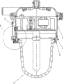
Fig. 1 looks schematic diagram for the utility model embodiment profile master.
Fig. 2 is the utility model embodiment profile schematic side view.
Fig. 3 is the utility model embodiment internal structure schematic diagram.
Fig. 4 is the F portion enlarged diagram of Fig. 3.
The specific embodiment
As Fig. 1,2,3,4, shown in 5, specific embodiment of the utility model is a kind of explosion-proof lamp, comprise upper shell 1, lower house 2, bulb 3, lower house 2 is arranged on the lower end of upper shell 1, and constitute with upper shell 1 and to be threaded, the a plurality of fixture blocks 21 of outer wall upper edge radial distribution of lower house 2, circle draw-in groove 211 is drawn in fixture block 21 side formation outwardly, annular is drawn circle 4 active card to be located at and is drawn in the circle draw-in groove 211 and constitutes matched in clearance, be fixed with boatswain chair 5 on the outer wall of upper shell 1, the other end of relative its stiff end forms flanging 51 on the boatswain chair 5, one pull bar 6 is movably set in the through hole 521 on the flanging 51 of boatswain chair 5 and constitutes matched in clearance, annular draws circle 4 one sides to form flange 41, form vertical bending plate 42 on the flange 41, along laterally offering fixing hole 421, the stiff end 61 of pull bar 6 forms the bending of radian on the bending plate 42, stiff end 61 activities are arranged in and constitute matched in clearance in the fixing hole 421, and the other end diameter of pull bar 6 is greater than the internal diameter of through hole 521.
The utility model has improved the mode of connecing of hanging of lower house 2, adopt chain to compare with prior art, pull bar 6 structures are simpler, and pull bar 6 draws being connected of circle 4 also convenient with annular, and annular to draw circle 4 and lower house 2 are matched in clearance because when backing out housing 2, can not drive annular yet and draw circle 4 to rotate, simple in structure, convenient and practical.
Claims (5)
1, a kind of explosion-proof lamp, comprise upper shell, lower house, lower house is arranged on the lower end of upper shell, and constitute to flexibly connect with upper shell, it is characterized in that: the outer wall of described lower house is provided with draw-in groove, annular draws the circle active card to be located at formation matched in clearance in the draw-in groove, be fixed with boatswain chair on the outer wall of upper shell, the other end of relative its stiff end forms flanging on the boatswain chair, one pull bar is movably set in the through hole on the flanging of boatswain chair and constitutes matched in clearance, the stiff end of pull bar is fixed on annular and draws on the circle, and the other end diameter of pull bar is greater than the internal diameter of through hole.
2, explosion-proof lamp according to claim 1, it is characterized in that: described annular draws circle one side to form flange, form vertical bending plate on the flange, the edge laterally offers fixing hole on the bending plate, the stiff end of pull bar forms the bending of radian, and the stiff end activity is arranged in and constitutes matched in clearance in the fixing hole.
3, explosion-proof lamp according to claim 1 and 2 is characterized in that: the circle draw-in groove is drawn in the side formation outwardly of a plurality of fixture blocks of outer wall upper edge radial distribution of described lower house, fixture block, constitutes above-mentioned draw-in groove.
4, explosion-proof lamp according to claim 1 and 2 is characterized in that: described lower house is threaded with upper shell.
5, explosion-proof lamp according to claim 1 and 2 is characterized in that: described lower house is connected with the upper shell screw.
Priority Applications (1)
| Application Number | Priority Date | Filing Date | Title |
|---|---|---|---|
| CNU2008200324034U CN201166340Y (en) | 2008-02-29 | 2008-02-29 | Explosion-proof lamp |
Applications Claiming Priority (1)
| Application Number | Priority Date | Filing Date | Title |
|---|---|---|---|
| CNU2008200324034U CN201166340Y (en) | 2008-02-29 | 2008-02-29 | Explosion-proof lamp |
Publications (1)
| Publication Number | Publication Date |
|---|---|
| CN201166340Y true CN201166340Y (en) | 2008-12-17 |
Family
ID=40191730
Family Applications (1)
| Application Number | Title | Priority Date | Filing Date |
|---|---|---|---|
| CNU2008200324034U Expired - Fee Related CN201166340Y (en) | 2008-02-29 | 2008-02-29 | Explosion-proof lamp |
Country Status (1)
| Country | Link |
|---|---|
| CN (1) | CN201166340Y (en) |
Cited By (2)
| Publication number | Priority date | Publication date | Assignee | Title |
|---|---|---|---|---|
| CN101871623A (en) * | 2010-06-29 | 2010-10-27 | 海洋王照明科技股份有限公司 | Lamp casing and lamp |
| CN111174182A (en) * | 2019-04-17 | 2020-05-19 | 海洋王照明科技股份有限公司 | Mining explosion-proof LED lamp |
-
2008
- 2008-02-29 CN CNU2008200324034U patent/CN201166340Y/en not_active Expired - Fee Related
Cited By (3)
| Publication number | Priority date | Publication date | Assignee | Title |
|---|---|---|---|---|
| CN101871623A (en) * | 2010-06-29 | 2010-10-27 | 海洋王照明科技股份有限公司 | Lamp casing and lamp |
| CN101871623B (en) * | 2010-06-29 | 2012-08-01 | 海洋王照明科技股份有限公司 | Lamp casing and lamp |
| CN111174182A (en) * | 2019-04-17 | 2020-05-19 | 海洋王照明科技股份有限公司 | Mining explosion-proof LED lamp |
Similar Documents
| Publication | Publication Date | Title |
|---|---|---|
| CN203742034U (en) | Lamplight decoration strip and curtain wall system | |
| CN203177089U (en) | Installing structure of light-emitting diode (LED) panel lamp | |
| CN201166340Y (en) | Explosion-proof lamp | |
| CN203298222U (en) | Movable outdoor LED lamp support | |
| CN206080037U (en) | Easily splice formula track linker | |
| CN202675164U (en) | Lampshade suspension structure for lamp | |
| CN202927775U (en) | Lamp positioning structure | |
| CN205388236U (en) | Flying saucer lamp | |
| CN205560418U (en) | Combination floor lamp | |
| CN210637989U (en) | Consolidate waterproof outdoor lamp stand | |
| CN201589131U (en) | Floor lamp | |
| CN201892172U (en) | New Downlight Mounting Frame | |
| CN220061504U (en) | Medical lighthouse | |
| CN206831340U (en) | New chandelier with wire protection function | |
| CN207065199U (en) | A kind of light fixture | |
| CN203286492U (en) | Emergency exit indicator lamp with multiple installation modes | |
| CN204785936U (en) | Wall lamp | |
| CN202501273U (en) | Lamp with buckle connection of lampshades | |
| CN203980184U (en) | Wall lamp | |
| CN202993084U (en) | Novel ceiling lamp frame | |
| CN204318354U (en) | A kind of curtain rail | |
| CN203533314U (en) | Lamp cap with GX53 energy-saving bulb as light source | |
| CN204213768U (en) | A kind of light | |
| CN203190093U (en) | Hinge type LED lamp box | |
| CN202629841U (en) | LED subway section lamp |
Legal Events
| Date | Code | Title | Description |
|---|---|---|---|
| C14 | Grant of patent or utility model | ||
| GR01 | Patent grant | ||
| C17 | Cessation of patent right | ||
| CF01 | Termination of patent right due to non-payment of annual fee |
Granted publication date: 20081217 |