CN201162019Y - Semi-high trestle type smoke drip catcher for blast furnace mixer - Google Patents
Semi-high trestle type smoke drip catcher for blast furnace mixer Download PDFInfo
- Publication number
- CN201162019Y CN201162019Y CNU2008200316292U CN200820031629U CN201162019Y CN 201162019 Y CN201162019 Y CN 201162019Y CN U2008200316292 U CNU2008200316292 U CN U2008200316292U CN 200820031629 U CN200820031629 U CN 200820031629U CN 201162019 Y CN201162019 Y CN 201162019Y
- Authority
- CN
- China
- Prior art keywords
- hood
- hot metal
- support
- petticoat pipe
- semi
- Prior art date
- Legal status (The legal status is an assumption and is not a legal conclusion. Google has not performed a legal analysis and makes no representation as to the accuracy of the status listed.)
- Expired - Lifetime
Links
Images


Landscapes
- Waste-Gas Treatment And Other Accessory Devices For Furnaces (AREA)
- Refinement Of Pig-Iron, Manufacture Of Cast Iron, And Steel Manufacture Other Than In Revolving Furnaces (AREA)
Abstract
The utility model discloses a semi-overhead dust extractor for a blast furnace mixer, which comprises a dedusting pipe (1), a supporting stand (2), a fixed hood (3) and a mobile hood (4), wherein the fixed hood (3) is arranged on the supporting stand (2), a guide rail (5) is arranged on the supporting stand (2), the mobile hood (4) can move along the guide rail (5), and can be combined with the fixed hood (3) to form an enclosed dust excluding hood, a hot-metal bottle overturn device (6) is arranged in the supporting stand (2), and the dedusting pipe (1) is arranged on one side of the fixed hood (3). The semi-overhead dust extractor is convenient for using, which can guarantee smoke to have high trapping rate when a blast furnace mixer receives iron. The semi-overhead dust extractor has excellent dedusting effect, which saves energy, lowers operation cost, and can simultaneously improve operating environment of operation staffs and reduce the operating rate of hoisting machines in workplaces.
Description
Technical field
The utility model relates to a kind of device of accepting high temperature fluid, converting the flue dust that the process of falling the high temperature fluid produces that is used for being captured in, relate in particular to a kind of be used for hot metal mixer at the hot metal mixer of the flue dust that produced by the iron process with half overhead system smoke catching device.
Background technology
In steelmaking process, hot metal mixer will be converted iron and the operation of tapping a blast furnace, in this process, can produce a large amount of flue dust, so just need carry out smoke catching with extraction hood, the layout that will accomplish extraction hood simultaneously neither influences production operation, and the capture rate of flue dust is high, and the difficulty of therefore carrying out the high-level efficiency smoke catching is very big.
The smoke catching of hot metal mixer in being subjected to the iron process is the dust separating main difficult point of hot metal mixer, at present smoke catching in the hot metal mixer production process and dust separating main mode are had: 1, set up one independently between hot metal mixer, whole workshop flue gas is captured, and carry out dedusting, reduced pollution to the factory building outside atmosphere; But this mode dedusting air quantity is big, the cost height, the post flue dust problem of operational zone does not solve in the factory building, workman's operating environment is poor, cause in the workshop operating ambient temperature of crane higher, up to more than 60 ℃, and the graphite in the flue dust and iron dust containing easily cause electric installation to damage, crane failure rate height, serviceman's maintenance inclement condition; 2, be subjected to the top of iron mouth that petticoat pipe is set at hot metal mixer, on the roof petticoat pipe be set simultaneously flue gas is captured; This mode is to the capture weak effect of flue dust and be subject to cross-flow influence, therefore causes the dedusting air quantity big, the cost height, and dust removing effects is poor; 3, by being provided with fixedly above the metal trough that side sucking hood captures flue gas converting; In this manner, convert the dolly of metal trough by a band, will convert metal trough and insert hot metal mixer, molten iron flows in the hot metal mixer through converting metal trough; Be subjected to the flue gas that produces in the iron process converting metal trough, by be subjected to iron position side top be provided with one fixedly side sucking hood capture, and carry out dedusting.Top, the left and right sides of dirt pits can only seal a part, the front portion can not seal, and influenced by crosswind owing to produce, and the dedusting air quantity is bigger, and dust removing effects is still undesirable.4, adopting the blowing and drawing type air curtain to cover draught hood captures flue gas; This kind mode is suspended to petticoat pipe directly over the hot metal mixer hot metal charging mouth center, and three exhausting of petticoat pipe leave one side and allow iron ladle pass in and out, the petticoat pipe end face adopts air curtain to stop flue gas rising flight, therefore the dedusting air quantity is less relatively, better dust removal effect, and do not influence the operation sight line.When the hot metal charging amount is big, when the flue gas lift velocity was fast, flue gas still can be dispersed in the factory building, and the air curtain air also increased exhaust gas volumn, thus dedusting to capture effect still not ideal.
The utility model content
The technical problems to be solved in the utility model provide a kind of easy to use and be subjected at hot metal mixer that flue gas trapping rate height in the iron process, exhaust gas volumn are little, hot metal mixer that good dedusting effect, energy consumption are low is with half overhead system smoke catching device.
For solving the problems of the technologies described above, the utility model adopts following technical scheme:
A kind of hot metal mixer is with half overhead system smoke catching device, comprise dust removing tube, this hot metal mixer also comprises support, fixedly petticoat pipe and movable gas hood with half overhead system smoke catching device, wherein fixedly petticoat pipe is located on the support, be provided with guide rail on support, movable gas hood can move along guide rail, and can be combined to form airtight dust excluding hood with fixing petticoat pipe, in support, be provided with the hot-metal bottle tipping device, and dust removing tube is located at a fixedly side of petticoat pipe.
Side at support is provided with moving door, this moving door and movable gas hood are positioned at the homonymy of support, and the travel direction of moving door is vertical with the travel direction of movable gas hood, and is movable about this moving door energy, makes things convenient for iron ladle turnover and iron ladle to be placed on the hot-metal bottle tipping device.
On the inwall of fixedly petticoat pipe and movable gas hood, be provided with refractory layer.
On support, be provided with smoke deflector.
Compared with prior art, the utility model technology has the following advantages:
1, the utility model is easy to use.In the utility model, movable gas hood can move along the guide rail on the support, and combine with fixing petticoat pipe and to form an airtight dust excluding hood, in this airtight dust excluding hood, be provided with the molten iron tank tipple, and the metal trough of converting that will be placed on the travelling car moves to corresponding position in this airtight dust excluding hood, movable gas hood is removed, the workshop casting crane is placed on iron ladle on the hot-metal bottle tipping device, after withdrawing from Deng the workshop casting crane, movable gas hood moved to and fixedly the petticoat pipe junction form above-mentioned airtight dust excluding hood, at this moment, start the hot-metal bottle tipping device, molten iron just flows in the hot metal mixer through converting metal trough, promptly finish the side hot metal charging of hot metal mixer, whole hot metal mixer is all carried out in seal closure by the iron process, and operation is very easy to go out iron process, and avoided directly carrying out toppling over of iron ladle with the workshop casting crane, reduced the operating rate of workshop casting crane.
2, the utility model can guarantee to be subjected at hot metal mixer that flue gas trapping rate height in the iron process, exhaust gas volumn are few, good dedusting effect, energy consumption be low.In the utility model, since movable gas hood can with fixing petticoat pipe in conjunction with forming airtight dust excluding hood, and convert metal trough convert iron produce dirt pits above be provided with smoke deflector, so just can guarantee that the flue gas that hot metal mixer produces all concentrates in the above-mentioned airtight dust excluding hood in being subjected to the iron process, because flue gas is more concentrated, therefore, blower fan just can be extracted the flue gas in the airtight dust excluding hood out, the amount that air outside the airtight dust excluding hood is taken away through dedusting fan is less, when therefore adopting the utility model, the required rate of air sucked in required of dedusting fan can reduce.Show that through on-the-spot test reach same dust removing effects, the rate of air sucked in required of dedusting fan of the present utility model can reduce 30%~50%, concrete numerical value is with reference to following table:
| The hot metal mixer nominal capacity | Adopt overhead guard to carry out the exhaust gas volumn (m that flue dust is caught 3/h) | Exhaust gas volumn (the m of smoke catching when adopting the utility model 3/h) |
| |
15~20 | ~10 |
| 600t | 25~25 | ~15 |
| 900t | 25~30 | ~20 |
| 1300t | 35~40 | ~25 |
3, the utility model can be realized energy-conservationly, reduces running cost.Because the movable gas hood in the utility model and fixedly petticoat pipe formed an airtight dust excluding hood, the whole iron process that is subjected to of hot metal mixer is all carried out in this airtight dust excluding hood, therefore for the hot metal mixer of same nominal capacity, reach same dust removing effects, the rate of air sucked in required of blower fan will reduce than other form method for dust removals when adopting the utility model, use just can be satisfied dust separating need of work than the motor of low capacity, has saved electric energy, thereby has reduced running cost.
4, the utility model can improve operating environment.The fixedly petticoat pipe in the utility model and the inwall of movable gas hood be provided with flame retardant coating, reduced the temperature that hot metal mixer is subjected to the Working environment of iron process, reduced thermal radiation, improved operator's Working environment; Simultaneously, owing to adopt dust trapping device of the present utility model, the flue dust that hot metal mixer whole is subjected to produce in the iron process all passes through dust removing tube and discharges, and the flue dust that is dispersed into the work factory building has seldom so just reduced because the consumer fault that graphite in the flue dust and iron dust containing cause.
Description of drawings
Below in conjunction with the drawings and specific embodiments the utility model is described in further detail:
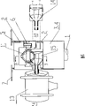
Fig. 1 is the structural representation of the utility model hot metal mixer with half overhead system smoke catching device.
Fig. 2 is the sectional view along the A-A line of Fig. 1.
Fig. 3 is the sectional view along the B-B line of Fig. 1.
Fig. 4 is the working process synoptic diagram of the utility model hot metal mixer with half overhead system smoke catching device.
Embodiment
With reference to Fig. 3, a kind of hot metal mixer is with half overhead system smoke catching device, comprise dust removing tube 1, this hot metal mixer also comprises support 2, fixedly petticoat pipe 3 and movable gas hood 4 with half overhead system smoke catching device, and wherein fixedly petticoat pipe 3 is located on the support 2, is provided with guide rail 5 on support 2, movable gas hood 4 can move along guide rail 5, and can be combined to form airtight dust excluding hood with fixing petticoat pipe 3, in support 2, be provided with hot-metal bottle tipping device 6, and dust removing tube 1 is located at a fixedly side of petticoat pipe 3; See figures.1.and.2, side at support 2 is provided with moving door 7, this moving door 7 and movable gas hood 4 are positioned at the homonymy of support 2, and the travel direction of moving door 7 is vertical with the travel direction of movable gas hood 4, movable about these moving door 7 energy, make things convenient for iron ladle turnover and iron ladle to be placed on the hot-metal bottle tipping device 6.The form of moving door 7 can be an independent door, also can be two doors of splitting; On the inwall of fixedly petticoat pipe 3 and movable gas hood 4, be provided with refractory layer 8; On support 2, be provided with smoke deflector 9, and smoke deflector 9 is positioned at the top that the hot metal mixer side is subjected to the iron mouth, is convenient to smoke catching.
In the present embodiment, hot-metal bottle tipping device 6 is arranged on the tipple support 10, simultaneously.The height of support 2 generally should be higher than the height of tipple support 10, and fixedly the thickness of petticoat pipe and movable gas hood is generally 100~300mm.
With reference to Fig. 1,2,3,4, working process of the present utility model is as follows: the metal trough 11 of converting that will be placed on the travelling car moves to and converts 15 places, ironworker position from maintenance station 14, movable gas hood 4 is removed, moving door 7 is opened, the workshop casting crane is placed on iron ladle 12 on the hot-metal bottle tipping device 6, and be locked, after withdrawing from Deng the workshop casting crane, movable gas hood 4 is moved,, close moving door 7 until being combined to form above-mentioned airtight dust excluding hood with fixing petticoat pipe, at this moment, start hot-metal bottle tipping device 6, molten iron just flows in the hot metal mixer 13 through converting metal trough 11, finishes the side hot metal charging technology of hot metal mixer 13.After converting metal trough 11 and reaching work-ing life, the metal trough 11 of converting that is placed on the travelling car just moves to maintenance station 14 from converting ironworker position 15, will convert metal trough 11 handlings with the workshop crane and walk, and changes the baked metal trough of converting; That changes converts metal trough, remove waste refractory materials, build by laying bricks or stones again, toast stand-by.The whole like this iron process that is subjected to is all carried out in above-mentioned airtight dust excluding hood, has improved operating environment, has improved efficiency of dust collection, and has realized energy-conservationly, has reduced running cost.
In the present embodiment, also can on the support 2 below two guide rails sealing plate be set, perforate on the sealing plate of the turnover position of converting metal trough 11 is convenient to allow and is converted metal trough 11 and free in and out, because sealing plate makes the sealing effectiveness of whole enclosed hood strengthen, dust removing effects is also better so like this.
Claims (4)
1, a kind of hot metal mixer is with half overhead system smoke catching device, comprise dust removing tube (1), it is characterized in that: this hot metal mixer also comprises support (2), fixedly petticoat pipe (3) and movable gas hood (4) with half overhead system smoke catching device, wherein fixedly petticoat pipe (3) is located on the support (2), on support (2), be provided with guide rail (5), movable gas hood (4) can move along guide rail (5), and can be combined to form airtight dust excluding hood with fixing petticoat pipe (3), in support (2), be provided with hot-metal bottle tipping device (6), and dust removing tube (1) is located at a fixedly side of petticoat pipe (3).
2, hot metal mixer according to claim 1 is with half overhead system smoke catching device, it is characterized in that: the side at support (2) is provided with moving door (7), this moving door (7) and movable gas hood (4) are positioned at the homonymy of support (2), and the travel direction of moving door (7) is vertical with the travel direction of movable gas hood (4).
3, hot metal mixer according to claim 1 is characterized in that with half overhead system smoke catching device: be provided with refractory layer (8) on the inwall of fixedly petticoat pipe (3) and movable gas hood (4).
4, hot metal mixer according to claim 1 and 2 is characterized in that: be provided with smoke deflector (9) on support (2) with half overhead system smoke catching device.
Priority Applications (1)
| Application Number | Priority Date | Filing Date | Title |
|---|---|---|---|
| CNU2008200316292U CN201162019Y (en) | 2008-01-30 | 2008-01-30 | Semi-high trestle type smoke drip catcher for blast furnace mixer |
Applications Claiming Priority (1)
| Application Number | Priority Date | Filing Date | Title |
|---|---|---|---|
| CNU2008200316292U CN201162019Y (en) | 2008-01-30 | 2008-01-30 | Semi-high trestle type smoke drip catcher for blast furnace mixer |
Publications (1)
| Publication Number | Publication Date |
|---|---|
| CN201162019Y true CN201162019Y (en) | 2008-12-10 |
Family
ID=40182960
Family Applications (1)
| Application Number | Title | Priority Date | Filing Date |
|---|---|---|---|
| CNU2008200316292U Expired - Lifetime CN201162019Y (en) | 2008-01-30 | 2008-01-30 | Semi-high trestle type smoke drip catcher for blast furnace mixer |
Country Status (1)
| Country | Link |
|---|---|
| CN (1) | CN201162019Y (en) |
Cited By (4)
| Publication number | Priority date | Publication date | Assignee | Title |
|---|---|---|---|---|
| CN102814493A (en) * | 2012-09-13 | 2012-12-12 | 中冶华天南京工程技术有限公司 | Environment-friendly molten iron transferring system |
| CN104815830A (en) * | 2015-04-24 | 2015-08-05 | 北京首钢国际工程技术有限公司 | Casting area moving type dust removing device for continuous casting machine |
| CN104907306A (en) * | 2015-06-16 | 2015-09-16 | 北方重工集团有限公司 | Retractable dust collecting cover |
| CN113263169A (en) * | 2021-04-07 | 2021-08-17 | 河北新兴铸管有限公司 | Hot metal bottle turns over iron system |
-
2008
- 2008-01-30 CN CNU2008200316292U patent/CN201162019Y/en not_active Expired - Lifetime
Cited By (4)
| Publication number | Priority date | Publication date | Assignee | Title |
|---|---|---|---|---|
| CN102814493A (en) * | 2012-09-13 | 2012-12-12 | 中冶华天南京工程技术有限公司 | Environment-friendly molten iron transferring system |
| CN104815830A (en) * | 2015-04-24 | 2015-08-05 | 北京首钢国际工程技术有限公司 | Casting area moving type dust removing device for continuous casting machine |
| CN104907306A (en) * | 2015-06-16 | 2015-09-16 | 北方重工集团有限公司 | Retractable dust collecting cover |
| CN113263169A (en) * | 2021-04-07 | 2021-08-17 | 河北新兴铸管有限公司 | Hot metal bottle turns over iron system |
Similar Documents
| Publication | Publication Date | Title |
|---|---|---|
| CN100577820C (en) | Mobile smoke blast trapping device for furnace mixer | |
| CN201166520Y (en) | Intermediate frequency furnace flue gas trapping device | |
| CN206911907U (en) | Double auto-converting type moves dust shield during a kind of iron making | |
| CN201162019Y (en) | Semi-high trestle type smoke drip catcher for blast furnace mixer | |
| CN210411847U (en) | Movable dust removal system for scrap steel cutting | |
| CN204321118U (en) | A kind of mobile smoke capturing device | |
| CN111872007A (en) | Multi-station movable dust removal device | |
| CN201406439Y (en) | Blast furnace fume gas shunting collecting and parallel dedusting device | |
| CN203731844U (en) | Electric arc furnace device | |
| CN104250840B (en) | Go out aluminium exhaust apparatus and method | |
| CN211367623U (en) | Combined converter tertiary dust collecting device and converter steelmaking system | |
| CN211084816U (en) | Automatic feeding device for aluminum ingots | |
| CN202730157U (en) | Wing-type top-suction dust removal device for blast furnace casting house | |
| CN201330259Y (en) | Blast furnace taphole-suspended lifting top-draft soot collector | |
| CN101559305B (en) | Blast furnace flue gas shunting trapping parallel dust-removing technology | |
| CN102912075A (en) | Method for improving coal gas recovery of semi-steel steel-making dry dedusting system | |
| CN216989097U (en) | Hot stuffy dust removal exhaust apparatus of steel slag | |
| CN202030779U (en) | Fume colleting shield for tilting trough of shaft furnace | |
| CN213826347U (en) | Ferrosilicon molten iron discharging process flue gas collection device | |
| CN210394480U (en) | Intermediate frequency furnace smelting production line with dust removal function | |
| CN212469187U (en) | Multi-station movable dust removal device | |
| CN204589218U (en) | A kind of movable dust removal cover of blast furnace iron notch | |
| CN201530837U (en) | CAS-OB dedusting device | |
| CN110551896A (en) | intermediate frequency furnace smelting production line with dust removal function | |
| CN205635664U (en) | Blast furnace iron notch dust collector |
Legal Events
| Date | Code | Title | Description |
|---|---|---|---|
| C14 | Grant of patent or utility model | ||
| GR01 | Patent grant | ||
| AV01 | Patent right actively abandoned |
Effective date of abandoning: 20080130 |
|
| C25 | Abandonment of patent right or utility model to avoid double patenting |