Submarine pipeline underwater flange seal protecting device
Technical field
The utility model relates to submarine pipeline equipment, relates in particular to a kind of seawater and marine growth of preventing and corrodes the submarine pipeline underwater flange seal protecting device of sea-bottom oil-gas conveyance conduit.
Background technique
With the shortage gradually of the landing field energy, marine energy becomes the important support point of economic development gradually.Last century the seventies, China has begun the development and utilization of marine energy, mainly is the development and utilization of submarine oil and rock gas.Through the development of three more than ten years, offshore oil and rock gas have become the important component part of China's energy.
The capital equipment of offshore oil and natural gas extraction is a drill platform, and the oil and natural gas transmission of exploiting out is main by submarine pipeline.But owing to be subjected to the influence of ocean condition, there are higher risk in submarine oil and gas extraction and transfer ratio land.In recent years, along with expand a large amount of uses of curved/flange of submarine pipeline, how to prevent that submarine pipeline from leaking is the major safety problems of seabed energy transmission.The internal corrosion of the erosion of the burn into marine growth of seawater, the mechanical deterioration of the operation of rise/casting anchor and fed sheet of a media is four big hidden danger of submarine pipeline safety.
Generally speaking, internal corrosion can solve by add corrosion inhibitor in medium; Method by buried pipeline solves the mechanical deterioration problem; The external coated corrosion-inhibiting coating of pipeline solves seawater and marine growth erosion problem.But for the pipeline protection of flange connecting and packing ring under water, at present domestic also do not have special device and corresponding techniques means thereof.External existing flange protection device; the annular cover body that only is provided in a side of the flange border; inject the hydrophoby binding material in the cover; only can play anti-corrosion protection effect after the curing to flange gasket; can't play a protective role to the anticorrosion of flange bolt; and its packing material costs an arm and a leg, and therefore the cost that causes a flanged joint of protection is difficult to promote the use of near 500,000 yuan.
The model utility content
Main purpose of the present utility model is to overcome the above-mentioned shortcoming that existing product exists; and provide a kind of submarine pipeline underwater flange seal protecting device; it comprises the body that is located at the flange outside, be filled in the foaming body of body inside and be filled in epoxy resin layer between two flanges and the packing ring outer rim; can prevent the erosion of seawater and marine growth effectively to flange and packing ring; prolong pipeline working life of flange connecting and packing ring under water; improve the security of operation of submarine pipeline; reduce the cost of offshore oil and natural gas extraction, the using effect ideal.
The purpose of this utility model is realized by following technological scheme.
The utility model submarine pipeline underwater flange seal protecting device is characterized in that, comprises the body that is located at the flange outside, is filled in the foaming body of body inside and is filled in epoxy resin layer between two flanges and the packing ring outer rim; This body comprises two and half cover bodies and end socket, and each half cover body two ends is respectively equipped with end socket, and the mutual involutory back of two and half cover bodies and end socket links into an integrated entity by the joint correspondence that is located at this apposition position; One of them half cover body is provided with gas tube, stabilizer ascending pipe, outlet pipe (stabilizer expansion tube), and another half cover body is provided with waste pipe; This gas tube, stabilizer ascending pipe and outlet pipe (stabilizer expansion tube) are equipped with the pillar cap.
Aforesaid submarine pipeline underwater flange seal protecting device; wherein two and half cover bodies are semicircular bodies; end socket is to be made of semicircular ring body corresponding with half cover body shape and one-body molded pipe clamp at semicircular ring body inner edge place; the outer rim of the semicircular ring body of this end socket and the two ends of half cover body welding one, pipe clamp inner edge place is provided with pad and is fastened on the body of adpting flange.
Aforesaid submarine pipeline underwater flange seal protecting device; wherein two and half cover bodies are the half-watt body; end socket is to be made of half-watt body corresponding with half cover body shape and one-body molded pipe clamp at half-watt body inner edge place; the outer rim of this end socket half-watt body and the two ends of half cover body welding one, pipe clamp inner edge place is provided with pad and is fastened on the body of adpting flange.
Aforesaid submarine pipeline underwater flange seal protecting device, wherein in the joint of two and half cover bodies and the mutual apposition position of end socket, the joint that is positioned at two and half cover bodies, one side is that hinge type connects, all the other joints are for being screwed together.
Aforesaid submarine pipeline underwater flange seal protecting device, wherein two and half cover bodies are all established rubber pad and are utilized bolton to be connected one with the joint of the mutual apposition position of end socket.
Aforesaid submarine pipeline underwater flange seal protecting device wherein is respectively equipped with several stiffening ribs on two and half cover bodies.
The beneficial effect of the utility model submarine pipeline underwater flange seal protecting device, it is rational in infrastructure simple, and cost is lower, only is equivalent to 1/10th of external like product; Easy construction, the reliability height; Have good antiseptic property, can effectively prevent the erosion of seawater and marine growth, improve the security of operation of submarine pipeline greatly the seabed flange; If pipeline uses through long-term, the difference that liquid difference variation or flange bolt tighten power produces minor leakage, and the foam material in epoxy resin between flange plate and the overcoat protective gear can also stop the seal for pipe joints under the lower pressure to be leaked.
Description of drawings:
Fig. 1 is the utility model submarine pipeline underwater flange seal protecting device structural representation.
Fig. 2 is the utility model submarine pipeline underwater flange seal protecting device user mode schematic representation.
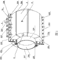
Major label description in figure: 1 flange, 2 cover bodies, 3 foaming bodies, 4 epoxy resin layers, 5 hinges, 6 flange bolts, the body of 7 adpting flanges, 8 anodes, 9 hangers, 10 pipe caps, 21 upper outlet bodies, 211 end sockets, 212 joints, 213 bolts (nut), 214 waste pipes, 215 stiffening ribs, 216 pads, 217 pipe clamps, 22 lower covers, 221 end sockets, 222 joints, 223 is the PUF ascending pipe, 224 bolts (nut), 225 pads, 226 stiffening ribs, 227 outlet pipes (foaming body expansion tube), 228 gas tubes, 229 pipe clamps.
Embodiment
Consult Fig. 1, shown in Figure 2, the utility model submarine pipeline underwater flange seal protecting device, it comprises the body 2 that is located at flange 1 outside, be filled in the foaming body 3 of body 2 inside and be filled in epoxy resin layer 4 between two flanges and the packing ring outer rim; This body 2 comprises two and half cover bodies 21 and 22 and end socket 211 and 221, two and half cover bodies 21 and 22 two ends be respectively equipped with end socket 211 and 221, two half cover bodies 21 and 22 and end socket 211 and 221 mutual involutory backs link into an integrated entity by joint 212 and 222 correspondences that are located at this apposition position; One of them half cover body 22 is provided with gas tube 228, stabilizer PUF ascending pipe 223, outlet pipe (stabilizer expansion tube) 227, another half cover body 21 is provided with waste pipe 214, and this gas tube 228, stabilizer ascending pipe 223, waste pipe 214 and outlet pipe 227 (stabilizer expansion tube) are equipped with pillar cap 10.
The utility model submarine pipeline underwater flange seal protecting device, wherein two and half cover bodies can be semicircular bodies, and end socket is to be made of semicircular ring body corresponding with half cover body shape and one-body molded pipe clamp at semicircular ring body inner edge place respectively; The two ends welding one of external edge of the semi-round ring shape of this end socket and half cover body, the pipe clamp inner edge place of end socket is provided with pad and is fastened on the body of adpting flange.
Consult Fig. 1, shown in Figure 2; the utility model submarine pipeline underwater flange seal protecting device; wherein two and half cover bodies 21 and 22 are the half-watt body; end socket 211 and 221 is to be made of half-watt annular solid corresponding with half cover body shape and one-body molded pipe clamp 217,229 at half-watt body inner edge place respectively; the two ends welding one of this end socket 211 and 221 half-watt body outer rim and half cover body 21 and 22, end socket 211 and 221 pipe clamp 217,229 inner edge places are provided with pad 216 and 225 and be fastened on the adpting flange body.
Consult Fig. 1, shown in Figure 2, the utility model submarine pipeline underwater flange seal protecting device, wherein two and half cover bodies 21 and 22 and the joint of end socket 211 and 221 mutual apposition positions in, the joint that is positioned at two and half cover bodies 21 and 22 1 sides is connected by hinge 5, and all the other joints are that bolt connects; The joint that also can be two and half cover bodies and the mutual apposition position of end socket is rubber pad bolt driving fit connection.
Consult Fig. 1, shown in Figure 2, the utility model submarine pipeline underwater flange seal protecting device wherein is respectively equipped with several stiffening ribs 215 and 226 on two and half cover bodies 21 and 22; And a corrosion protection anode 8 and hanger 9 are installed respectively also on two and half cover bodies 21 and 22.
Consult Fig. 1, shown in Figure 2, the preparation of the utility model submarine pipeline underwater flange seal protecting device and installation, two and half cover bodies 21 and 22 that adopt steel plate to roll half-watt shape, one-body molded respectively on this half cover body 21 and 22 by 3 stiffening ribs 215 and 226; Wherein be preset with gas tube 228, stabilizer ascending pipe 223 and outlet pipe 227 (stabilizer expansion tube) on half cover body 22, be preset with waste pipe 214 on second half cover body 21, this gas tube 228, stabilizer ascending pipe 223, waste pipe 214 and outlet pipe 227 (stabilizer expansion tube) are equipped with pipe cap; Punching out and two and half cover bodies 21 and the corresponding half-watt shape of 22 shapes end socket 211 and 221 and one-body molded pipe clamp 217,229 on the steel plate identical at this half-watt shape end socket 211 and 221 inner edge places with cover body steel plate specification, and make pipe clamp sidewall and half-watt body inner edge be vertical configuration, with the outer edge of two half-watt shape end sockets 211 and 221 respectively with the two ends welding one of two and half cover bodies 21 and 22, end socket 211 and 221 pipe clamp inner edge place are provided with pad 216 and 225 and be fastened on the body 7 of adpting flange; Two and half cover bodies 21 and 22 and the mutual apposition position weldering of end socket 211 and 221 establish joint 212 and 222, the joint that wherein is positioned at two and half cover bodies 21 and 22 1 sides is connected by hinge 5, remaining joint bolt 213 is with 224 and driving fit is connected.In addition, weld respectively on two and half cover bodies 21 and 22 and establish hanger 9, use when supplying water fitting operation; And, also be welded with corrosion protection anode 8 on two and half cover bodies 21 and 22 respectively.This corrosion protection anode 8 and hanger 9 are prior art, and the corrosion protection anode and the hanger that are provided with in its structure and working principle and the existing underwater flange protective gear are identical, so, no longer give unnecessary details.
Dive beneath the water by the diving personnel and to search out the flange that needs protection, use under water and around flange, go out enough big working pit towards mud equipment, use the dirt in cleaning tool and high pressure water cleaning flange and the flange gap then, clear up the dirt of each 50cm left and right sides scope inner conduit surface of flange both sides again; In the flange gap, inject encapsulating epoxy resin under water, after waiting to solidify, with two and half cover bodies 21 that are half-watt shape and the 22 sheathed outsides that are installed in underwater flange 1 of a side by hinge 5 connections, to be placed on end socket pipe clamp inner edge place respectively with the corresponding pad of end socket pipe clamp inner edge then, and be fastened on the body 7 of adpting flange 1, again with two and half cover bodies 21 and 22 and the joint closing of end socket 211 and 221 mutual apposition positions together, 213 and 224 bolts (nut) are installed, are made two and half cover bodies screw togather the moulding one.Gas ducting is connected to gas tube 228 mouths of pipe of half cover body 22 by the diving personnel, exhaust line (foaming and intumescing pipe) is connected to the tube head of the outlet pipe 227 of half cover body 22, and polyurethane foam material (PUF) pipeline is connected to stabilizer ascending pipe 223 mouths of pipe of this half cover body 22, open 214 and 228 valve, close 223 and 227 valve; (pressure is determined according to the depth of water to the inner injecting compressed air of the body of flange seal protecting device by the water surface, be generally the depth of water/10+0.02Mpa), treat to continue ventilation more than 30 minutes after the water discharge in the flange seal protecting device body, close 214 and 228 valves, open outlet pipe 227 (foaming and intumescing pipe) valve and stabilizer ascending pipe 223 valves, to the inner polyurethane foam material (PUF) that injects of flange seal protecting device body, foamed time generally is decided to be 90 seconds (s), and injection amount is calculated according to the body internal capacity of flange seal protecting device; Foaming body is removed each temporary pipeline after filling and finishing, and throttle down is installed each mouth of pipe pillar cap, prevents the foaming body immersion; At last, landfill sandbag in working pit, protection pipeline.
The design and the working principle of the utility model submarine pipeline underwater flange seal protecting device be, the adpting flange of submarine pipeline and packing ring are exposed in the seawater, therefore as easy as rolling off a logly is subjected to the erosion of seawater and marine growth and damages, and influences the security of operation of pipeline.After the flange installation; use submarine pipeline underwater flange seal protecting device of the present utility model; can prevent the erosion of seawater and marine growth effectively to flange and packing ring; prolong pipeline working life of flange connecting and packing ring under water; improve the security of operation of submarine pipeline; reduce the cost of offshore oil and natural gas extraction, the using effect ideal.At first use epoxy resin layer to fill up the gap that forms between two flanges and the packing ring, make seawater can not enter the gap that forms between two flanges and the packing ring, avoid seawater and marine growth this part erosion of flange; Fill up foaming body then at the outside sheathed body of flange, and in the body inner space, flange is sealed fully, thorough and seawater completely cuts off, and therefore effective protection flange can not be subjected to the erosion of seawater and marine growth, makes the design service life of flange life-span greater than pipeline.
The advantage of the utility model submarine pipeline underwater flange seal protecting device is; can effectively protect flange can not be subjected to the erosion of seawater and marine growth; improve working life; foam material in epoxy resin between flange plate and the overcoat protective gear can stop the seal for pipe joints under the lower pressure to be leaked; guarantee the safe operation of submarine pipeline; simple and reasonable, material price is lower, just promotes the use of.
The above, it only is preferred embodiment of the present utility model, be not that the utility model is done any pro forma restriction, every foundation technical spirit of the present utility model all still belongs in the scope of technical solutions of the utility model any simple modification, equivalent variations and modification that above embodiment did.