CN201125834Y - Energy-saving type hydroturbine - Google Patents
Energy-saving type hydroturbine Download PDFInfo
- Publication number
- CN201125834Y CN201125834Y CNU2007201283427U CN200720128342U CN201125834Y CN 201125834 Y CN201125834 Y CN 201125834Y CN U2007201283427 U CNU2007201283427 U CN U2007201283427U CN 200720128342 U CN200720128342 U CN 200720128342U CN 201125834 Y CN201125834 Y CN 201125834Y
- Authority
- CN
- China
- Prior art keywords
- impeller
- water
- hydrophone
- energy
- main shaft
- Prior art date
- Legal status (The legal status is an assumption and is not a legal conclusion. Google has not performed a legal analysis and makes no representation as to the accuracy of the status listed.)
- Expired - Fee Related
Links
Images


Classifications
-
- Y—GENERAL TAGGING OF NEW TECHNOLOGICAL DEVELOPMENTS; GENERAL TAGGING OF CROSS-SECTIONAL TECHNOLOGIES SPANNING OVER SEVERAL SECTIONS OF THE IPC; TECHNICAL SUBJECTS COVERED BY FORMER USPC CROSS-REFERENCE ART COLLECTIONS [XRACs] AND DIGESTS
- Y02—TECHNOLOGIES OR APPLICATIONS FOR MITIGATION OR ADAPTATION AGAINST CLIMATE CHANGE
- Y02E—REDUCTION OF GREENHOUSE GAS [GHG] EMISSIONS, RELATED TO ENERGY GENERATION, TRANSMISSION OR DISTRIBUTION
- Y02E10/00—Energy generation through renewable energy sources
- Y02E10/20—Hydro energy
Abstract
The utility model discloses an energy-saving hydraulic turbine which comprises an external box body, a bearing, a principal shaft and an impeller of the principal shaft. The invention is characterized in that the external box body is provided with a principal shaft impeller driving mechanism which emits jetting water from the inner side to the outside. The driving mechanism comprises an inner box body and water injecting openings which are provided in 360 degree direction of the external circumference. The base or side surface of the internal box body is connected with a water inlet opening. The external box body is provided with a water outlet mechanism, namely a water outlet opening connected with the side surface of the external box body. The water injecting opening is an independent plug-in type installation part. The water outlet mechanism can be a form of sprinkler which is designed to be integrated with the hydraulic turbine, and comprises a sprinkler impeller and a sprinkler pipe which is engaged with the sprinkle impeller. When the water inlet opening is vertically inserted from the base of the inner box body, the sprinkle impeller is sleeved outside the impeller of the principal shaft. When the water inlet opening is horizontally inserted from the side surface of the inner box body, the sprinkler impeller is correspondingly arranged below the impeller of the principal shaft. The utility model has the advantages of energy saving, high cooling efficiency, no drift-water and suitability for the improvement of existing cooling tower.
Description
Technical field
The utility model relates to the cooling tower system, is a kind of novel energy-saving water turbine.
Background technique
In the cooling unit of present cooling tower system, hot water, by the rotary fan air draft at top, is taken away the heat in the water, to reach the purpose of cooling in the process that falls from the eminence of tower trickle down.The rotation of fan is rotated drive by motor and speed reducer device, and motor operation all the year round can consume a large amount of electric power.The purchasing of speed reducer, installation and maintenance simultaneously also needs cost, in the transmission process of speed reducer, also can lose part energy.Simultaneously in following time, drenched with hot water in the cooling tower system, and the mode of employing is generally the mode of dispersion, can produce a large amount of water that wafts in the course of the work like this, and the one, caused the waste of water resources, the 2nd, also influence the effect of cooling, the 3rd, environment has been produced influence.And the hydrophone that spreads of existing outlet system is a separated type on the market, can take bigger space, thereby influences flowing of hot air.
The position of water intake and water outlet, also difference in addition along with the different model of cooling tower.If that changes is too big, can cause engineering work load increasing and the prolongation of operation cycle, do not do a good job and also can destroy cooling tower and water pipe system.Existing water intake is generally fixedly bore and fixed qty, under different situations, can't regulate like this, can't make full use of energy.
The model utility content
For addressing the above problem, the utility model provides a kind of energy that utilizes the hot water margin head, promotes the flabellum rotation by water turbine, thereby reaches the energy-saving water turbine of suction heat.
The technological scheme that the utility model adopted is as follows:
A kind of energy-saving water turbine comprises outer casing, bearing, main shaft, is placed in main shaft impeller on the main shaft, is placed in the fan on the main shaft, it is characterized in that, is provided with the drive unit of the main shaft impeller of dispersing injection water from inside to outside in the described outer casing.
The drive unit of described main shaft impeller comprises internal box and the some water orifices of being located on the internal box of being located at outer casing inside, the blade of described main shaft impeller is between outer casing and internal box, internal box bottom or side are connected with water intake, outer casing is provided with effluent mechanism, and described effluent mechanism is the form of the water outlet that is connected with the outer casing side.
Described water orifice is along distributing on the excircle 360 degree directions of internal box, and high pressure water sprays from water orifice, impacts the main shaft impeller from inside to outside, thereby drives the fan rotation on the main shaft.
Each is individual part described water orifice, and the employing plug-in type is installed, and adopts the baffle plate sealing to insert mouth when not assigning; The sectional shape of described water orifice is a rectangle; The quantity and the cross-sectional sizes of described water orifice are set according to actual needs.
The angle of the water spraying direction of described water orifice and the circular arc tangential line of its position is between 0 °~60 ° or 120 °~180 °.
Described effluent mechanism is the form of spreading hydrophone, and it and water turbine adopt integrated design, and such design makes the volume of whole device littler, is more conducive to the ventilation in cooling tower space; Described spread hydrophone comprise spread the hydrophone impeller and with spread that the hydrophone impeller is connected spread the hydrophone water pipe.
Described water intake inserts from the internal box bottom vertical, and the described hydrophone impeller that spreads is nested in main shaft impeller outside; Perhaps water intake inserts from internal box side level, spreads hydrophone impeller correspondence and is located at main shaft impeller below.Aforesaid way needs the concrete condition according to different cooling tower inlet and outlet systems, can MIN transformation original system with how as the foundation of selecting.
Described spreading between hydrophone impeller and the main shaft impeller is provided with the guiding swash plate.
The described hydrophone water pipe lower end of spreading is provided with several short tubes vertically downward.
With respect to prior art, the utlity model has following beneficial effect: (1) has cancelled motor and reducer arrangement, has saved electric power; (2) make full use of water and spray remaining inertia behind the impeller, drive and spread the hydrophone rotation, reach the purpose of evenly spreading water; (3) because the integrated design of spreading hydrophone and water turbine makes the volume of whole device littler, save the height in space, increased the stroke that hot water falls, thereby improved the efficient of cooling; (4) be provided with short tube, the water phenomenon of having avoided wafing owing to spread hydrophone water pipe lower end.(5) owing to adopt the mode of injection water from inside outwards, so water intake can be located at side or bottom, is convenient to the renovation and utilization to existing cooling tower.
Description of drawings
Below in conjunction with the drawings and specific embodiments the utility model is described in further details
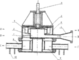
Fig. 1 is the utility model vertical inlet structural representation
Fig. 2 is the F-F cross-sectional view of Fig. 1
Fig. 3 is the horizontal water inlet structure schematic representation of the utility model
Fig. 4 is the G-G cross-sectional view of Fig. 3
Fig. 5 spreads the schematic representation behind the hydrophone for first kind of structure of the utility model adopts
Fig. 6 is the E-E cross-sectional view of Fig. 5
Fig. 7 spreads the schematic representation behind the hydrophone for second kind of structure of the utility model adopts
Fig. 8 is the A-A cross-sectional view of Fig. 7
Fig. 9 is the B-B cross-sectional view of Fig. 7
Figure 10 is the C-C cross-sectional view of Fig. 7
Embodiment
As Fig. 1, Fig. 2, Fig. 3, energy-saving water turbine shown in Figure 4, overall two round box that are configured to are nested together, and promptly outer casing 6 and internal box 2 are nested together.Internal box 2 bottoms (as Fig. 1) or side (as Fig. 3) are connected with water intake 1, and outer casing 6 sides are connected with water outlet 11.High-pressure water flow enters internal box 2 from water intake 1, after the impact impeller blade, flows out from water outlet 11.
When effluent mechanism adopt with the water turbine integrated design spread the form of hydrophone the time, spread hydrophone and can be divided into two kinds of different structures according to the difference of water inlet position, as Fig. 5, Fig. 6 is nesting type: from the Vertical direction water inlet, spread hydrophone impeller 8 and be nested in main shaft impeller 4 outsides; As Fig. 7 to Figure 10 is last following formula: from the substantially horizontal water inlet, spread hydrophone impeller 8 correspondences and be located at main shaft impeller 4 belows.
The press water of coming in by water intake 1, enter internal box 2, the spout 3 that is no less than 4 is arranged around internal box 2, each water orifice 3 go out water line, all the circular arc tangential line with the position has a certain degree, the value of angle is 0 ° to 60 ° or 120 ° to 180 °, with this near water outlet direction along tangent to periphery, outwards spray the main shaft impeller 4 on the high speed water jet impact main shaft 5, and make it to rotate, the main shaft 5 that connects with it also rotates simultaneously, drives the flabellum rotation that main shaft 5 upper ends connect then, and hot blast is discharged.
And current still have certain speed after impacting main shaft impeller 4, and this part water moves between main shaft impeller 4 and outer casing 6, impact through guiding swash plate 7 and spread hydrophone impeller 8, and the hydrophone rotation is spread in drive.The inclination of guiding swash plate 7 and the absolute value of moving direction angle are between 5 ° to 60 °.Main shaft impeller 4, spread hydrophone impeller 8, water orifice 3 ultimate range in the axial direction in 40 centimetres.The design has made full use of the kinetic energy that impacts main shaft impeller 4 back water.
The last flow direction of water that impact is spread after the hydrophone impeller 8 spread hydrophone water pipe 9, spreads hydrophone water pipe 9 and has several holes be used to spread water on direction vertically downward, in order not produce the water that wafts, is connected to short tube 10 vertically downward on the hole, is used to guide water to flow vertically downward.
Claims (10)
1. energy-saving water turbine, comprise outer casing (6), bearing, main shaft (5), be placed in the main shaft impeller (4) on the main shaft (5), it is characterized in that, be provided with the drive unit of the main shaft impeller (4) of dispersing injection water from inside to outside in the described outer casing (6).
2. energy-saving water turbine according to claim 1 is characterized in that, the drive unit of described main shaft impeller (4) comprises is located at outer casing (6) inner internal box (2) and some water orifices of being located on the internal box (2) (3); The blade of described main shaft impeller (4) is positioned between outer casing (6) and the internal box (2), internal box (2) bottom or side are connected with water intake (1), outer casing (6) is provided with effluent mechanism, and described effluent mechanism is the form of the water outlet (11) that is connected with outer casing (6) side.
3. as energy-saving water turbine as described in the claim 2, it is characterized in that described water orifice (3) is along distributing on the excircle 360 degree directions of internal box (2).
4. as energy-saving water turbine as described in the claim 3, it is characterized in that each is individual part described water orifice (3), adopt plug-in type to install, adopt the baffle plate sealing to insert mouthful when assigning; The sectional shape of described water orifice (3) is a rectangle.
5. as energy-saving water turbine as described in claim 3 or 4, it is characterized in that the angle of the water spraying direction of described water orifice (3) and the circular arc tangential line of its position is between 0 °~60 ° or 120 °~180 °.
6. as energy-saving water turbine as described in the claim 2, it is characterized in that, the form of described effluent mechanism (11) for spreading hydrophone, described spread hydrophone comprise spread hydrophone impeller (8) and with spread that hydrophone impeller (8) is connected spread hydrophone water pipe (9); Described hydrophone and the water turbine of spreading adopts integrated design.
7. as energy-saving water turbine as described in claim 2 or 6, it is characterized in that described water intake (1) inserts from internal box (2) bottom vertical, the described hydrophone impeller (8) that spreads is nested in main shaft impeller (4) outside.
8. as energy-saving water turbine as described in claim 2 or 6, it is characterized in that described water intake (1) inserts from internal box (2) side level, described hydrophone impeller (8) correspondence of spreading is located at main shaft impeller (4) below.
9. as energy-saving water turbine as described in the claim 6, it is characterized in that described spreading is provided with guiding swash plate (7) between hydrophone impeller (8) and the main shaft impeller (4).
10. as energy-saving water turbine as described in the claim 6, it is characterized in that described hydrophone water pipe (9) lower end of spreading is provided with several short tubes (10) vertically downward.
Priority Applications (1)
| Application Number | Priority Date | Filing Date | Title |
|---|---|---|---|
| CNU2007201283427U CN201125834Y (en) | 2007-07-30 | 2007-07-30 | Energy-saving type hydroturbine |
Applications Claiming Priority (1)
| Application Number | Priority Date | Filing Date | Title |
|---|---|---|---|
| CNU2007201283427U CN201125834Y (en) | 2007-07-30 | 2007-07-30 | Energy-saving type hydroturbine |
Publications (1)
| Publication Number | Publication Date |
|---|---|
| CN201125834Y true CN201125834Y (en) | 2008-10-01 |
Family
ID=39999303
Family Applications (1)
| Application Number | Title | Priority Date | Filing Date |
|---|---|---|---|
| CNU2007201283427U Expired - Fee Related CN201125834Y (en) | 2007-07-30 | 2007-07-30 | Energy-saving type hydroturbine |
Country Status (1)
| Country | Link |
|---|---|
| CN (1) | CN201125834Y (en) |
Cited By (11)
| Publication number | Priority date | Publication date | Assignee | Title |
|---|---|---|---|---|
| CN102996319A (en) * | 2011-09-13 | 2013-03-27 | 襄阳六合春发电研究中心 | Tap ring on periphery of water and wind power generation groove |
| CN106640491A (en) * | 2017-01-13 | 2017-05-10 | 溧阳市金土地节能科技有限公司 | Efficient and durable special water turbine for cooling tower |
| CN109441699A (en) * | 2018-10-18 | 2019-03-08 | 深圳朴方环保发展有限公司 | A kind of power generating network system of siphon pipe network composition |
| CN109488511A (en) * | 2018-10-15 | 2019-03-19 | 深圳朴方环保发展有限公司 | A kind of hydroelectric installation |
| CN111379653A (en) * | 2018-12-28 | 2020-07-07 | 李岭群 | Permanent magnet suspension water turbine device |
| CN112049748A (en) * | 2020-08-14 | 2020-12-08 | 深圳广蓝电力有限公司 | Water turbine and hydroelectric generator |
| CN112879197A (en) * | 2021-01-18 | 2021-06-01 | 深圳广蓝电力有限公司 | Water turbine and hydroelectric generator |
| CN113323785A (en) * | 2021-07-21 | 2021-08-31 | 陆庆森 | Straight-flow side deflection discrete water turbine |
| WO2022032643A1 (en) * | 2020-08-14 | 2022-02-17 | 深圳广蓝电力有限公司 | Water turbine and hydroelectric generator |
| WO2022151468A1 (en) * | 2021-01-18 | 2022-07-21 | 深圳广蓝电力有限公司 | Hydro turbine and hydroelectric generator |
| CN116085170A (en) * | 2023-04-10 | 2023-05-09 | 广东海洋大学 | Multi-rotor structure residual pressure energy recovery device and sea water desalination system |
-
2007
- 2007-07-30 CN CNU2007201283427U patent/CN201125834Y/en not_active Expired - Fee Related
Cited By (12)
| Publication number | Priority date | Publication date | Assignee | Title |
|---|---|---|---|---|
| CN102996319A (en) * | 2011-09-13 | 2013-03-27 | 襄阳六合春发电研究中心 | Tap ring on periphery of water and wind power generation groove |
| CN106640491A (en) * | 2017-01-13 | 2017-05-10 | 溧阳市金土地节能科技有限公司 | Efficient and durable special water turbine for cooling tower |
| CN106640491B (en) * | 2017-01-13 | 2024-02-27 | 溧阳市金土地节能科技有限公司 | Special hydraulic turbine of high-efficient durable cooling tower |
| CN109488511A (en) * | 2018-10-15 | 2019-03-19 | 深圳朴方环保发展有限公司 | A kind of hydroelectric installation |
| CN109441699A (en) * | 2018-10-18 | 2019-03-08 | 深圳朴方环保发展有限公司 | A kind of power generating network system of siphon pipe network composition |
| CN111379653A (en) * | 2018-12-28 | 2020-07-07 | 李岭群 | Permanent magnet suspension water turbine device |
| CN112049748A (en) * | 2020-08-14 | 2020-12-08 | 深圳广蓝电力有限公司 | Water turbine and hydroelectric generator |
| WO2022032643A1 (en) * | 2020-08-14 | 2022-02-17 | 深圳广蓝电力有限公司 | Water turbine and hydroelectric generator |
| CN112879197A (en) * | 2021-01-18 | 2021-06-01 | 深圳广蓝电力有限公司 | Water turbine and hydroelectric generator |
| WO2022151468A1 (en) * | 2021-01-18 | 2022-07-21 | 深圳广蓝电力有限公司 | Hydro turbine and hydroelectric generator |
| CN113323785A (en) * | 2021-07-21 | 2021-08-31 | 陆庆森 | Straight-flow side deflection discrete water turbine |
| CN116085170A (en) * | 2023-04-10 | 2023-05-09 | 广东海洋大学 | Multi-rotor structure residual pressure energy recovery device and sea water desalination system |
Similar Documents
| Publication | Publication Date | Title |
|---|---|---|
| CN201125834Y (en) | Energy-saving type hydroturbine | |
| CN201540040U (en) | Cooling tower for waterpower fan | |
| CN103335539B (en) | Blower-free is unpowered energy consumption safe environment protection type cooling tower | |
| CN104728048A (en) | Wind power and water power mixed power generation device of cooling tower | |
| CN201155405Y (en) | Double water inlet type energy-saving hydroturbine | |
| CN105973025A (en) | Novel energy-saving spraying ventilation cooling tower | |
| CN203274584U (en) | Mechanical draft cooling tower provided with high-position water collecting device | |
| CN203479053U (en) | Fan-free power-energy-consumption-free safe environmental-friendly cooling tower | |
| CN103017565A (en) | Variable flow combined type energy-saving type cooling tower of hydraulic driving impeller | |
| CN203053258U (en) | Hydraulic driving blade wheel variable flow combined type energy-saving cooling tower | |
| CN201803605U (en) | Polygonal counter flow cooling tower | |
| CN103438725A (en) | Water cooling tower | |
| CN201311199Y (en) | Forced draft type packless spray cooling tower | |
| CN202329273U (en) | Spraying propulsion energy-saving circular cooling tower | |
| CN212109635U (en) | Pipeline structure of transverse flow closed cooling tower spray pump | |
| CN205102630U (en) | Improve cooling tower | |
| CN204064026U (en) | Adverse current rotary-jet cooling tower | |
| CN211060694U (en) | Water kinetic energy jet device | |
| CN203810955U (en) | Power-consumption-free water energy recovery cooling tower | |
| CN203785482U (en) | Water cooling tower | |
| CN202787260U (en) | Cylinder type diesel pile hammer capable of carrying out forced cooling | |
| CN207963538U (en) | A kind of high-performance combined-type cooling tower | |
| CN201974064U (en) | Cooling tower of water dynamic fan | |
| CN213747971U (en) | High-efficient cooling tower | |
| CN201434608Y (en) | Energy-saving cold water tower |
Legal Events
| Date | Code | Title | Description |
|---|---|---|---|
| C14 | Grant of patent or utility model | ||
| GR01 | Patent grant | ||
| C17 | Cessation of patent right | ||
| CF01 | Termination of patent right due to non-payment of annual fee |
Granted publication date: 20081001 Termination date: 20110730 |