CN201115093Y - Ventilation door plate - Google Patents
Ventilation door plate Download PDFInfo
- Publication number
- CN201115093Y CN201115093Y CNU2007201753386U CN200720175338U CN201115093Y CN 201115093 Y CN201115093 Y CN 201115093Y CN U2007201753386 U CNU2007201753386 U CN U2007201753386U CN 200720175338 U CN200720175338 U CN 200720175338U CN 201115093 Y CN201115093 Y CN 201115093Y
- Authority
- CN
- China
- Prior art keywords
- door
- plate
- air filter
- scaleboard
- ventilation
- Prior art date
- Legal status (The legal status is an assumption and is not a legal conclusion. Google has not performed a legal analysis and makes no representation as to the accuracy of the status listed.)
- Expired - Lifetime
Links
Images


Abstract
The utility model discloses a ventilating door panel, comprising a door panel, an inner door scale board and a dust gauze component; wherein, the door panel is an installation substrate which is provided with a louvered hole opening downward; the inner door scale is an installation support and the inner door scale board and the door panel are sealed together; the dust gauze component and the inner door scale board are fixedly connected together and the dust gauze component is provided with a louvered hole opening upward, which is sealed together with the inner door scale board. The ventilating door panel of the utility model realizes the ventilation and heat exchange between the inner side and the outer side of the cabinet, on the basis of realizing the sealing function.
Description
Technical field
The utility model relates to a kind of communication cabinet, relates in particular to a kind of ventilation door-plate of communication cabinet.
Background technology
In the communications field, used a large amount of outdoor communication cabinets at present, or the communication cabinet of some indoor special seal requirement.
The seal request of IP55 (a kind of shell protection calling hierarchy requires dustproof, the anti-spraying of shell) is the basic demand of this class cabinet design.
For reaching the seal request of IP55, the door-plate design of this class rack is generally full-closed structure; Or door-plate design ventilation hole, but ventilation and rack internal insulation, to prevent the rack water inlet, promptly door-plate and rack inside do not have the ability of ventilation heat exchange.
But because the communication cabinet internal element all is heater usually, in order to guarantee the reliably working of built-in function unit, system need with extraneous heat exchange to reach the purpose of self cooling.
So present communication cabinet has guaranteed the requirement of sealing, but the ventilation heat exchange between can not realizing inside and outside the communication cabinet by door-plate.
The utility model content
The utility model provides a kind of ventilation door-plate, in order to the ventilation heat exchange problem between solving inside and outside the communication cabinet.
Ventilation door-plate described in the utility model comprises: door-plate 1, inner door scaleboard 3, Air Filter assembly 5;
Wherein, door-plate 1 is provided with the ventilating blind fenestra that Open Side Down in the above for matrix is installed; Inner door scaleboard 3 supports for installing, and described inner door scaleboard 3 is sealed with described door-plate 1;
Described Air Filter assembly 5 is fixed together with described inner door scaleboard 3, is provided with the ventilating blind fenestra that opening makes progress above the Air Filter assembly 5, and described Air Filter assembly 5 is sealed with described inner door scaleboard 3.
Further, described Air Filter assembly 5 specifically comprises: ventilating board 6, Air Filter 7, pressing plate 8;
Wherein, Air Filter 7 is filled in pressing plate 8, and pressing plate 8 is fixed together with ventilating board 6.
Further, described pressing plate 8 and ventilating board 6 are fixed together by screw.
Further, described Air Filter (7) is made for sponge material.
Further, the blinds fenestra that descends row most of described door-plate 1 is lower than the installation faying face of inner door scaleboard 3 and door-plate 1.
Further, described Air Filter assembly 5 and described inner door scaleboard 3 are fixed together by screw.
Further, be sealed by sealing strip 2 between described inner door scaleboard 3 and the described door-plate 1.
Further, be sealed by sealing strip 4 between described Air Filter assembly 5 and the described inner door scaleboard 3.
In sum, the utility model has improved a kind of ventilation door-plate, Open Side Down for the blinds fenestra of door-plate 1 of the present utility model, the blinds fenestra opening of Air Filter assembly 5 upwards, and by with the cooperating of sealing strip, sponge air filter, reach the IP55 seal request, outer jet water can't arrive rack inside, can resident water liquid in the door-plate, and it has well realized the inside and outside air-conditioning requirement of rack on the basis of realizing sealing.
Description of drawings
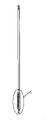
Fig. 1 is the outside overall schematic of ventilation door-plate described in the utility model;
Fig. 2 is the inboard overall schematic of ventilation door-plate described in the utility model;
Fig. 3 is the structural representation of ventilation door-plate described in the utility model;
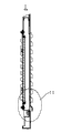
Fig. 4 is a ventilation door-plate hermetically-sealed construction cross-sectional view described in the utility model;
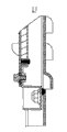
Fig. 5 is the details enlarged drawing of I part in the ventilation door-plate hermetically-sealed construction cross-sectional view shown in Figure 4;
Fig. 6 is the details enlarged drawing of II part in the details enlarged drawing shown in Figure 5;
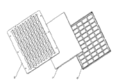
Fig. 7 is the structural representation of Air Filter assembly described in the utility model.
Embodiment
Below in conjunction with accompanying drawing ventilation door-plate described in the utility model is elaborated.
As depicted in figs. 1 and 2, Fig. 1 and Fig. 2 are respectively the outside and the inboard overall schematic of described ventilation door-plate.
As shown in Figure 3, Fig. 3 is the concrete structure schematic diagram of described ventilation door-plate, and described ventilation door-plate mainly comprises: door-plate 1, sealing strip 2, inner door scaleboard 3, sealing strip 4, Air Filter assembly 5.
Wherein, door-plate 1 is opened wind blinds fenestra in the above for matrix is installed, and Open Side Down for described blinds fenestra; Inner door scaleboard 3 supports for installing, its with door-plate 1 between sealing strip 2 is installed, realize sealing; Certainly, those of ordinary skills should be understood that between described inner door scaleboard 3 and the described door-plate 1 and also can seal by other modes, as long as reach the effect of sealing.
Described Air Filter assembly 5 is fixed together with described inner door scaleboard 3, in specific implementation process of the present utility model, described Air Filter assembly 5 can be fastenedly connected by screw with inner door scaleboard 3, the opening of the ventilating blind fenestra of described Air Filter assembly 5 upwards, between described Air Filter assembly 5 and the described inner door scaleboard 3 sealing strip 4 is installed, realizes sealing.Certainly, those of ordinary skills should be understood that between described dust preventing component 5 and the described inner door scaleboard 3 and also can seal by other modes, as long as reach the effect of sealing.
Fig. 4 is described ventilation door-plate hermetically-sealed construction cross-sectional view, and Fig. 5 is the details enlarged drawing of I part in the ventilation door-plate hermetically-sealed construction cross-sectional view shown in Figure 4, and Fig. 6 is the details enlarged drawing of II part in the details enlarged drawing shown in Figure 5.As can be seen, outside the rack, Open Side Down for door-plate 1 blinds fenestra from Fig. 4 to Fig. 6; Rack inboard, Air Filter assembly 5 blinds fenestra openings are upwards; Its principle is that injection water can only spray the access door intralamellar part from the below, and because Air Filter assembly 5 blinds fenestra openings make progress, water droplet will inevitably flow back to door-plate inside, and can not enter rack inside.
And the blinds fenestra that descends row most of door-plate 1 is a little less than the installation faying face of inner door scaleboard 3 with door-plate 1.Like this, can guarantee that the inner ponding of door-plate can flow out, and realizes not ponding.
As shown in Figure 7, Fig. 7 is described Air Filter assembly 5 concrete structure schematic diagrames, and described Air Filter assembly mainly comprises: ventilating board 6, Air Filter 7, pressing plate 8.
Wherein, Air Filter 7 is filled in pressing plate 8, and pressing plate 8 is fixed together with ventilating board 6, and in specific implementation process of the present utility model, described pressing plate 8 can be fastenedly connected by screw with ventilating board 6; Air Filter 7 is generally sponge material, and sponge material can reach dustproof and absorb the effect of moisture.
In sum, ventilation door-plate described in the utility model, Open Side Down for the blinds fenestra of its door-plate 1, the blinds fenestra opening of Air Filter assembly 5 upwards, and by with the cooperating of sealing strip, sponge air filter, reach the IP55 seal request, outer jet water can't arrive rack inside, can resident water liquid in the door-plate, and it has well realized the inside and outside air-conditioning requirement of rack on the basis of realizing sealing.
The above; it only is the preferable embodiment of utility model; but protection range of the present utility model is not limited thereto; anyly be familiar with those skilled in the art in the technical scope that the utility model discloses; the variation that can expect easily or replacement all should be encompassed within the protection range of the present utility model.Therefore, the protection range of utility model should be as the criterion with the protection range of claims.
Claims (8)
1. a ventilation door-plate is characterized in that, comprising: door-plate (1), inner door scaleboard (3), Air Filter assembly (5);
Wherein, door-plate (1) is provided with the ventilating blind fenestra that Open Side Down in the above for matrix is installed; Inner door scaleboard (3) supports for installing, and described inner door scaleboard (3) is sealed with described door-plate (1);
Described Air Filter assembly (5) is fixed together with described inner door scaleboard (3), is provided with the ventilating blind fenestra that opening makes progress above the Air Filter assembly (5), and described Air Filter assembly (5) is sealed with described inner door scaleboard (3).
2. ventilation door-plate according to claim 1 is characterized in that, described Air Filter assembly (5) specifically comprises: ventilating board (6), Air Filter (7), pressing plate (8);
Wherein, Air Filter (7) is filled in pressing plate (8), and pressing plate (8) is fixed together with ventilating board (6).
3. ventilation door-plate according to claim 2 is characterized in that, described pressing plate (8) is fixed together by screw with ventilating board (6).
4. ventilation door-plate according to claim 2 is characterized in that, described Air Filter (7) is made for sponge material.
5. according to any described ventilation door-plate in the claim 1 to 4, it is characterized in that the blinds fenestra that descends row most of described door-plate 1 is lower than the installation faying face of inner door scaleboard 3 and door-plate 1.
6. according to any described ventilation door-plate in the claim 1 to 4, it is characterized in that described Air Filter assembly (5) is fixed together by screw with described inner door scaleboard (3).
7. according to any described ventilation door-plate in the claim 1 to 4, it is characterized in that, be sealed by sealing strip (2) between described inner door scaleboard (3) and the described door-plate (1).
8. according to any described ventilation door-plate in the claim 1 to 4, it is characterized in that, be sealed by sealing strip (4) between described Air Filter assembly (5) and the described inner door scaleboard (3).
Priority Applications (1)
| Application Number | Priority Date | Filing Date | Title |
|---|---|---|---|
| CNU2007201753386U CN201115093Y (en) | 2007-09-03 | 2007-09-03 | Ventilation door plate |
Applications Claiming Priority (1)
| Application Number | Priority Date | Filing Date | Title |
|---|---|---|---|
| CNU2007201753386U CN201115093Y (en) | 2007-09-03 | 2007-09-03 | Ventilation door plate |
Publications (1)
| Publication Number | Publication Date |
|---|---|
| CN201115093Y true CN201115093Y (en) | 2008-09-10 |
Family
ID=39966845
Family Applications (1)
| Application Number | Title | Priority Date | Filing Date |
|---|---|---|---|
| CNU2007201753386U Expired - Lifetime CN201115093Y (en) | 2007-09-03 | 2007-09-03 | Ventilation door plate |
Country Status (1)
| Country | Link |
|---|---|
| CN (1) | CN201115093Y (en) |
Cited By (7)
| Publication number | Priority date | Publication date | Assignee | Title |
|---|---|---|---|---|
| CN102256467A (en) * | 2011-06-29 | 2011-11-23 | 上海三思电子工程有限公司 | Light-emitting diode (LED) display screen body framework |
| CN103826407A (en) * | 2012-11-16 | 2014-05-28 | 通用电气公司 | Method and apparatus for cover for enclosure and enclosure having cover |
| CN107200187A (en) * | 2016-03-16 | 2017-09-26 | 马丁工程技术(昆山)有限公司 | Air bubble with louvre blade dustproof construction |
| CN107910791A (en) * | 2017-12-26 | 2018-04-13 | 索凌电气有限公司 | A kind of distribution box and its ventilation chamber door |
| CN109219289A (en) * | 2018-10-11 | 2019-01-15 | 青岛特锐德电气股份有限公司 | A kind of waterproof cover and water repellent component for JP cabinet |
| CN113286505A (en) * | 2021-05-24 | 2021-08-20 | 北京广利核系统工程有限公司 | Ventilation shielding window and electrical equipment |
| CN113473773A (en) * | 2021-06-18 | 2021-10-01 | 苏州浪潮智能科技有限公司 | Automatic server rack windshield that removes dust |
-
2007
- 2007-09-03 CN CNU2007201753386U patent/CN201115093Y/en not_active Expired - Lifetime
Cited By (8)
| Publication number | Priority date | Publication date | Assignee | Title |
|---|---|---|---|---|
| CN102256467A (en) * | 2011-06-29 | 2011-11-23 | 上海三思电子工程有限公司 | Light-emitting diode (LED) display screen body framework |
| CN103826407A (en) * | 2012-11-16 | 2014-05-28 | 通用电气公司 | Method and apparatus for cover for enclosure and enclosure having cover |
| CN107200187A (en) * | 2016-03-16 | 2017-09-26 | 马丁工程技术(昆山)有限公司 | Air bubble with louvre blade dustproof construction |
| CN107910791A (en) * | 2017-12-26 | 2018-04-13 | 索凌电气有限公司 | A kind of distribution box and its ventilation chamber door |
| CN109219289A (en) * | 2018-10-11 | 2019-01-15 | 青岛特锐德电气股份有限公司 | A kind of waterproof cover and water repellent component for JP cabinet |
| CN113286505A (en) * | 2021-05-24 | 2021-08-20 | 北京广利核系统工程有限公司 | Ventilation shielding window and electrical equipment |
| CN113286505B (en) * | 2021-05-24 | 2022-11-25 | 北京广利核系统工程有限公司 | Ventilation shielding window and electrical equipment |
| CN113473773A (en) * | 2021-06-18 | 2021-10-01 | 苏州浪潮智能科技有限公司 | Automatic server rack windshield that removes dust |
Similar Documents
| Publication | Publication Date | Title |
|---|---|---|
| CN201115093Y (en) | Ventilation door plate | |
| CN201629923U (en) | Novel outdoor cabinet | |
| CN107396581A (en) | A kind of ventilated type outdoor power cabinet system | |
| CN201726618U (en) | Waterproof and dustproof case | |
| CN201160348Y (en) | One kind communication rack | |
| CN202759691U (en) | Machine cabinet door and machine cabinet | |
| CN206005041U (en) | A kind of crane electrical control cubicles | |
| CN208257195U (en) | Outdoor box switching station comprising DTU distribution terminal | |
| CN200973206Y (en) | Water-froof device for outdoor cabinet | |
| CN112282609B (en) | Door and window with fresh air ventilation function | |
| CN201533109U (en) | Outdoor combined power cabinet | |
| CN210832419U (en) | Building outer wall ventilation unit that insulates against heat | |
| CN213682689U (en) | Outer circulation ventilation curtain | |
| CN210659838U (en) | Multi-cavity drainage plate used in door and window | |
| CN217538074U (en) | Miniature communication computer lab of assembling | |
| CN216253726U (en) | Outdoor integrated communication cabinet | |
| CN206113164U (en) | Air condensing units protective housing | |
| CN217789148U (en) | High temperature resistant switch board that leakproofness is good | |
| CN205985833U (en) | Waterproof distribution box | |
| CN216625007U (en) | Heat dissipation rainproof distribution box for building construction | |
| CN202103801U (en) | Far-end machine chassis of outdoor communication repeater | |
| CN212376552U (en) | Drainage structure of outdoor cabinet shutter | |
| CN205355605U (en) | Ventilation cooling structure of container of integrated electrical equipment cabinet | |
| CN216204264U (en) | Total heat recovery system for animal laboratory | |
| CN218091674U (en) | Whole roofing system of green photovoltaic of modularization |
Legal Events
| Date | Code | Title | Description |
|---|---|---|---|
| C14 | Grant of patent or utility model | ||
| GR01 | Patent grant | ||
| CX01 | Expiry of patent term | ||
| CX01 | Expiry of patent term |
Granted publication date: 20080910 |