CN201112159Y - Automatic changeover using permanent magnetic operating mechanism - Google Patents
Automatic changeover using permanent magnetic operating mechanism Download PDFInfo
- Publication number
- CN201112159Y CN201112159Y CNU2007201123413U CN200720112341U CN201112159Y CN 201112159 Y CN201112159 Y CN 201112159Y CN U2007201123413 U CNU2007201123413 U CN U2007201123413U CN 200720112341 U CN200720112341 U CN 200720112341U CN 201112159 Y CN201112159 Y CN 201112159Y
- Authority
- CN
- China
- Prior art keywords
- permanent
- over
- automatic change
- pair
- base plate
- Prior art date
- Legal status (The legal status is an assumption and is not a legal conclusion. Google has not performed a legal analysis and makes no representation as to the accuracy of the status listed.)
- Expired - Lifetime
Links
Images


Abstract
The utility model discloses an automatic conversion switch which adopts a permanent operation mechanism. A pair of single pole or multi-pole moving contact systems, a pair of single pole or multi-pole arc extinguishing systems and a fixed contact which is arranged corresponding to the moving contact system are arranged on a base plate. The automatic conversion switch is characterized in that the base plate is also provided with a pair of brackets and two permanent magnetism operation mechanisms; the bracket is provided with a pair of rotary shafts which are linked with the moving contact systems and two rotary shafts are respectively provided with a link rod which is linked with the two permanent magnetism operation mechanisms. The operation mechanism of the automatic conversion switching device of the utility model adopts the permanent magnetism operation mechanism and the automatic conversion switch is characterized by realizing an automatic conversion switching device with one power terminal or another power terminal being closed (or cut) by adopting the permanent magnetism operation mechanism to drive the rotary shaft to rotate at certain angles through the link rod, sparing the mechanical tripping and fastening system of the traditional automatic conversion switch and keeping the automatic conversion switch in the closing or tripping position by the retention generated by the permanent magnet.
Description
Technical field
The utility model relates to low-voltage electrical apparatus, relates in particular to automatic transfer switching electric appliance, specifically a kind of automatic transfer switching electric appliance that adopts permanent magnet mechanism.
Background technology
Existing automatic transfer switching electric appliance divides PC level and CB level two big classes, and the operating mechanism of PC level automatic change-over all is to adopt coil moment excitatory, motion in the coil rotating shaft rotation that drives a power supply or another power supply by mechanical chain mechanism unshakable in one's determination, thereby realize the power end or the another one power end closure of automatic change-over, finish the conversion of the power supply from a road to other a tunnel in the circuit.This kind mechanism element is many, complex structure, and the requirement on machining accuracy height, the difficult control of reliability and consistency, the life-span generally has only 3000-8000 time, and needs periodic maintenance.As device for switching indispensable in the distribution system, concerning automatic change-over, will realize high reliability, long-life, non-maintaining requirement now, all also can't meet the demands fully by the automatic change-over of present this structure.And adopted the middle pressure vacuum circuit-breaker of permanent-magnet operating mechanism now widely-used, and realized high reliability, the long-life, non-maintainingly, easy to operate satisfied the market development demand, still, only be used on the less direct-acting vacuum circuit breaker of contact travel.
Summary of the invention
To be solved in the utility model is the above-mentioned defective that prior art exists, and aims to provide a kind of PC level automatic transfer switching electric appliance of employing permanent-magnet operating mechanism of novelty, and this structure can be applicable to the PC level automatic transfer switching electric appliance of various performances.
The technical scheme that addresses the above problem employing is: a kind of automatic change-over that adopts permanent-magnet operating mechanism, base plate be provided with the utmost point one to one or multipole moving contact system, one to one the utmost point or multipole arc quenching system with the fixed contact of the relative configuration of described moving contact system, it is characterized in that also being provided with on the described base plate pair of brackets and two permanent-magnet operating mechanisms, described support is provided with the rotating shaft of a pair of and described a pair of moving contact system interlock, is respectively equipped with the connecting rod with described two permanent-magnet operating mechanism interlocks in described two rotating shafts.
The operating mechanism of automatic transfer switching electric appliance of the present utility model adopts permanent-magnet operating mechanism, the characteristics of this utility model are: realize the automatic transfer switching electric appliance of a power end or another one power end closure or disconnection thereby adopt permanent-magnet operating mechanism to turn an angle by connecting rod drive rotating shaft, the machinery of having cancelled traditional automatically moving change over switch is threaded off, fastener system, and the confining force that produces by permanent magnet remains on branch, closing position with automatic change-over.
Can axially stagger as two permanent magnet mechanisms of the present utility model is fixed on the base plate, also can be set in parallel on the base plate.
Further improve again as of the present utility model, described permanent-magnet operating mechanism comprises static iron core, moving iron core, permanent magnet, switching winding and closing coil, described switching winding and closing coil split up and down, described moving iron core is located in the coil rack of switching winding and closing coil, and described permanent magnet places between switching winding and the closing coil; The described moving iron core upper end connecting rod corresponding with it connects.
Description of drawings
The utility model is described in further detail below in conjunction with drawings and Examples.
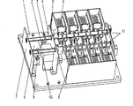
Fig. 1 is the axonometric drawing of automatic change-over of the present utility model;
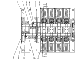
Fig. 2 is the structural representation of automatic change-over of the present utility model;
Fig. 3 be Fig. 2 along A-A to cutaway view, wherein two power ends all are in gate-dividing state;
Fig. 4 is that automatic change-over east power end of the present utility model closes a floodgate the structure chart during the power end separating brake of left side;
Fig. 5 is an automatic change-over east power end separating brake of the present utility model, the structure chart when the left side power end closes a floodgate;
Fig. 6 is the be arranged in parallel axonometric drawings of the execution mode on base plate of two permanent-magnet operating mechanisms of automatic change-over of the present utility model.
Fig. 7 is the structural representation of automatic change-over of the present utility model at Fig. 6 execution mode, and wherein two of automatic change-over power ends all are in gate-dividing state.
Embodiment
With reference to Fig. 1,2, it is a kind of multipole (can be the two poles of the earth, three utmost points or four utmost points, embodiment be depicted as four utmost points among the figure) automatic change-over that the utility model adopts the automatic transfer switching electric appliance of permanent-magnet operating mechanism.It comprises base plate 1, and support 5, support 7, fixed contact 12 are housed on base plate 1, and permanent-magnet operating mechanism 2, permanent-magnet operating mechanism 8 as figure axially dislocation are arranged in support 5 and the support 7 and are fixed on the base plate 1.Arc quenching system 6 is equipped with in fixed contact 12 tops.A pair of moving contact system 11 is arranged in two power ends of automatic change-over, and an end is fixed on the base plate 1, and rotating shaft 4, rotating shaft 10 penetrate respectively in the square hole of a moving contact system 11 of its correspondence.Connecting rod 3 is fixed in the rotating shaft 4, and is connected with the moving iron core of permanent-magnet operating mechanism 2 by axle 13.Connecting rod 9 is fixed in the rotating shaft 10, and is connected with the moving iron core of permanent-magnet operating mechanism 8 by axle 13.
With reference to Fig. 3, described permanent-magnet operating mechanism 8 comprises fixed core 17, moving iron core 14, permanent magnet 16, switching winding 15 and closing coil 18, described moving unshakable in one's determination 14 are located in the coil rack, described switching winding 15 and closing coil 18 are separately positioned on the two ends in the fixed core 17, described permanent magnet 16 is fixed on the fixed core 17, and places between switching winding 15 and the closing coil 18; Described moving 14 upper ends unshakable in one's determination are connected with described connecting rod 9.
The structure of permanent-magnet operating mechanism 2 is identical with permanent-magnet operating mechanism 8, and its moving 14 upper ends unshakable in one's determination are connected with described connecting rod 3.
State when two power ends of shown in Figure 3 is automatic change-over all are in separating brake.
Permanent-magnet operating mechanism is to adopt electromagnetism actuating, permanent magnetism maintenance, Electronic Control, compare with traditional mechanism and to have lacked that divide-shut brake position machinery is threaded off, fastener system, only the confining force that produces by permanent magnet just can allow circuit breaker remain on branch, close on the position, part has only its 40%, thereby has realized high reliability, long-life, non-maintaining, easy to operate.
As shown in Figure 3, when automatic change-over east power end is in the separating brake position, when there is switching signal the outside, the magnetic potential that closing coil 18 produces left, and it is synthetic with the magnetic field superposition of permanent magnet 16 generations, under the power effect of resultant magnetic field, moving iron core 14 drives in official hour and finishes stroke H, moving simultaneously unshakable in one's determination 14 connecting rods 9 that drive in the rotating shaft 10 10 rotate around the shaft, the angle that rotating shaft 10 is rotated under the drive of connecting rod 9 just in time satisfies automatic change-over close a floodgate required the overcome contact pressure and the required excess of stroke, guarantees the breaking capacity and the temperature rise of automatic change-over.After feed motion finished, each position component as shown in Figure 4.At this moment, the magnetic line of force that permanent magnet 16 produces from fixed core 17 bottoms through fixed core 17 left sides, fixed core 17 middle parts, left side permanent magnet 16, moving unshakable in one's determination 14, right side permanent magnet 16, fixed core 17 right sides get back to fixed core 17 bottoms at last, form a closed magnetic circuit around closing coil 18, near the switching winding the magnetic line of force almost disappears, Distribution of Magnetic Field guarantees that automatic change-over is in reliable closing position near closing coil.Find out that from the above course of work having only moving iron core 14 is moving components, the machinery of having cancelled easy initiating failure from structure takes off, locker, has improved the reliability of system, need not replace and regulate any parts, and the life-span can reach 3-5 ten thousand times.Simultaneously, also need not provide power supply energy, thereby energy consumption is also lower in the on/off switch position.
Fig. 5 be Fig. 2 along B-B to cutaway view, shown in the figure, the left power end of automatic change-over is in the structure chart when gate-dividing state under "on" position, the east power end, and wherein the principle of this left side power end closure is as the principle of the east power end closure shown in Fig. 3,4.
Fig. 6 is be arranged in parallel structure charts on base plate of another kind of two permanent-magnet operating mechanisms of automatic change-over of the present utility model.
Fig. 7 is two permanent-magnet operating mechanisms of automatic change-over of the present utility model when being arranged in parallel, and during any one power end closed, the operation principle of permanent-magnet operating mechanism is identical with last execution mode in the automatic change-over.Here just repeat no more.
What should be understood that is: the foregoing description is just to explanation of the present utility model, rather than to restriction of the present utility model, any innovation and creation that do not exceed in the utility model connotation scope all fall within the protection range of the present utility model.
Claims (5)
1. automatic change-over that adopts permanent-magnet operating mechanism, base plate (1) is provided with the utmost point or multipole moving contact system (11) one to one, one to one the utmost point or multipole arc quenching system (6) with the fixed contact (12) of the relative configuration of described moving contact system (11), it is characterized in that (1) also is provided with pair of brackets (7 on the described base plate, 5) and two permanent-magnet operating mechanisms (8,2), described support (7,5) be provided with the rotating shaft (4 of a pair of and described a pair of moving contact system (11) interlock, 10), described two rotating shafts (4,10) be respectively equipped with on and described two permanent-magnet operating mechanisms (2,8) connecting rod (3 of interlock, 9).
2. automatic change-over as claimed in claim 1 is characterized in that described two permanent-magnet operating mechanisms (8,2) axially stagger to be arranged on the described base plate (1).
3. automatic change-over as claimed in claim 1 is characterized in that described two permanent-magnet operating mechanisms (8,2) are set in parallel on the described base plate (1).
4. as any one described automatic change-over of claim 1-3, it is characterized in that described each permanent-magnet operating mechanism (8,2) comprises static iron core (17), moving iron core (14), permanent magnet (16), switching winding (15) and closing coil (18), described switching winding (15) and closing coil (18) split up and down, described moving iron core (14) is located in the coil rack of switching winding (15) and closing coil (18), and described permanent magnet (16) places between switching winding (15) and the closing coil (18); Described moving iron core (14) upper end is connected on its corresponding connecting rod (3,9).
5. automatic change-over as claimed in claim 4 is characterized in that described two rotating shafts (4,10) penetrate respectively in the square hole of a moving contact system (11) of its correspondence to locate.
Priority Applications (1)
| Application Number | Priority Date | Filing Date | Title |
|---|---|---|---|
| CNU2007201123413U CN201112159Y (en) | 2007-07-27 | 2007-07-27 | Automatic changeover using permanent magnetic operating mechanism |
Applications Claiming Priority (1)
| Application Number | Priority Date | Filing Date | Title |
|---|---|---|---|
| CNU2007201123413U CN201112159Y (en) | 2007-07-27 | 2007-07-27 | Automatic changeover using permanent magnetic operating mechanism |
Publications (1)
| Publication Number | Publication Date |
|---|---|
| CN201112159Y true CN201112159Y (en) | 2008-09-10 |
Family
ID=39963903
Family Applications (1)
| Application Number | Title | Priority Date | Filing Date |
|---|---|---|---|
| CNU2007201123413U Expired - Lifetime CN201112159Y (en) | 2007-07-27 | 2007-07-27 | Automatic changeover using permanent magnetic operating mechanism |
Country Status (1)
| Country | Link |
|---|---|
| CN (1) | CN201112159Y (en) |
Cited By (7)
| Publication number | Priority date | Publication date | Assignee | Title |
|---|---|---|---|---|
| CN101145468B (en) * | 2007-07-27 | 2010-11-10 | 浙江正泰电器股份有限公司 | Automatic switching switch adopting permanent-magnet operation device |
| WO2016173461A1 (en) * | 2015-04-28 | 2016-11-03 | 上海电科电器科技有限公司 | Operating mechanism of circuit breaker |
| WO2016173464A1 (en) * | 2015-04-28 | 2016-11-03 | 上海电科电器科技有限公司 | Secondary latch mechanism for operating mechanism of circuit breaker |
| WO2016173462A1 (en) * | 2015-04-28 | 2016-11-03 | 上海电科电器科技有限公司 | Fusion welding isolation mechanism for operating mechanism of circuit breaker |
| WO2016206067A1 (en) * | 2015-06-26 | 2016-12-29 | 康明斯发电Ip公司 | Permanent magnet operating mechanism for use in automatic transfer switch |
| CN111463033A (en) * | 2014-01-30 | 2020-07-28 | 康明斯发电Ip公司 | Automatic transfer switch and method thereof |
| US11495417B2 (en) | 2017-09-15 | 2022-11-08 | Abb Schweiz Ag | Switching apparatus |
-
2007
- 2007-07-27 CN CNU2007201123413U patent/CN201112159Y/en not_active Expired - Lifetime
Cited By (15)
| Publication number | Priority date | Publication date | Assignee | Title |
|---|---|---|---|---|
| CN101145468B (en) * | 2007-07-27 | 2010-11-10 | 浙江正泰电器股份有限公司 | Automatic switching switch adopting permanent-magnet operation device |
| CN111463033A (en) * | 2014-01-30 | 2020-07-28 | 康明斯发电Ip公司 | Automatic transfer switch and method thereof |
| US10199196B2 (en) | 2015-04-28 | 2019-02-05 | Seari Electric Technology Co., Ltd. | Two-level latch mechanism for operation mechanism of circuit breaker |
| WO2016173462A1 (en) * | 2015-04-28 | 2016-11-03 | 上海电科电器科技有限公司 | Fusion welding isolation mechanism for operating mechanism of circuit breaker |
| WO2016173464A1 (en) * | 2015-04-28 | 2016-11-03 | 上海电科电器科技有限公司 | Secondary latch mechanism for operating mechanism of circuit breaker |
| US10256066B2 (en) | 2015-04-28 | 2019-04-09 | Seari Electric Technology Co., Ltd. | Operation mechanism of circuit breaker |
| US10332715B2 (en) | 2015-04-28 | 2019-06-25 | Seari Electric Technology Co., Ltd. | Fusion welding isolation mechanism for operation mechanism of circuit breaker |
| RU2696014C2 (en) * | 2015-04-28 | 2019-07-30 | Сэари Электрик Технолоджи Ко., Лтд. | Two-stage mechanical interlocking mechanism for automatic circuit breaker actuator |
| RU2699389C2 (en) * | 2015-04-28 | 2019-09-05 | Сэари Электрик Технолоджи Ко., Лтд. | Actuator of automatic circuit breaker |
| RU2699386C2 (en) * | 2015-04-28 | 2019-09-05 | Сэари Электрик Технолоджи Ко., Лтд. | Fusion welding isolation mechanism for automatic circuit breaker actuator |
| WO2016173461A1 (en) * | 2015-04-28 | 2016-11-03 | 上海电科电器科技有限公司 | Operating mechanism of circuit breaker |
| WO2016206067A1 (en) * | 2015-06-26 | 2016-12-29 | 康明斯发电Ip公司 | Permanent magnet operating mechanism for use in automatic transfer switch |
| CN107924774A (en) * | 2015-06-26 | 2018-04-17 | 康明斯发电Ip公司 | Permanent-magnet operating mechanism for automatic change-over |
| US10692677B2 (en) | 2015-06-26 | 2020-06-23 | Cummins Power Generation Ip Inc. | Permanent magnet operating mechanism for use in automatic transfer switch |
| US11495417B2 (en) | 2017-09-15 | 2022-11-08 | Abb Schweiz Ag | Switching apparatus |
Similar Documents
| Publication | Publication Date | Title |
|---|---|---|
| CN101145468B (en) | Automatic switching switch adopting permanent-magnet operation device | |
| CN201112159Y (en) | Automatic changeover using permanent magnetic operating mechanism | |
| CN202217627U (en) | Magnetic latching relay | |
| CN101430986B (en) | Outdoor high-voltage permanent magnet type vacuum circuit breaker | |
| CN105118746B (en) | Automatic divide-shut brake drive mechanism | |
| CN103077837A (en) | Automatic change-over switch and method of automatically changing over power supply | |
| CN101022061B (en) | Air circuit breaker with permanent magnetic operating mechanism | |
| CN205752007U (en) | A kind of outdoor high-voltage vacuum breaker | |
| CN102064600A (en) | Tristable differential permanent magnetic operating mechanism | |
| CN202977311U (en) | Electromagnetic relay and switching device | |
| CN203456944U (en) | Double-power switch | |
| CN101188166A (en) | A permanent magnetic mechanism | |
| CN203288541U (en) | A novel contactor auxiliary contact apparatus | |
| CN202332750U (en) | Control and protection switch | |
| CN201038045Y (en) | Air circuit breaker adopting permanent-magnet operation device | |
| CN103560055A (en) | Permanent magnet variable air gap limited rotation angle motor operation mechanism of high-voltage breaker | |
| CN103681124A (en) | Sealed multi-electrode circuit breaker | |
| CN201413798Y (en) | Sealed magnetic control isolating switch | |
| CN202339884U (en) | Permanent operating mechanism | |
| CN205303294U (en) | Load switch on adoption permanent -magnet type operating device's post | |
| CN202736828U (en) | Indoor AC high-voltage vacuum circuit breaker | |
| CN104658814B (en) | breaker and its transmission device | |
| CN210052686U (en) | High-speed electromagnetic permanent magnet composite operating mechanism | |
| CN204991515U (en) | Two power change -over switch's quick switching mechanism | |
| CN203859051U (en) | Three-phase directly operated type disconnecting switch |
Legal Events
| Date | Code | Title | Description |
|---|---|---|---|
| C14 | Grant of patent or utility model | ||
| GR01 | Patent grant | ||
| AV01 | Patent right actively abandoned |
Granted publication date: 20080910 Effective date of abandoning: 20070727 |