CN201081163Y - LED lamp holder structure - Google Patents
LED lamp holder structure Download PDFInfo
- Publication number
- CN201081163Y CN201081163Y CNU2007201219670U CN200720121967U CN201081163Y CN 201081163 Y CN201081163 Y CN 201081163Y CN U2007201219670 U CNU2007201219670 U CN U2007201219670U CN 200720121967 U CN200720121967 U CN 200720121967U CN 201081163 Y CN201081163 Y CN 201081163Y
- Authority
- CN
- China
- Prior art keywords
- lamp
- cover
- back cover
- led
- holder structure
- Prior art date
- Legal status (The legal status is an assumption and is not a legal conclusion. Google has not performed a legal analysis and makes no representation as to the accuracy of the status listed.)
- Expired - Fee Related
Links
Images


Landscapes
- Arrangement Of Elements, Cooling, Sealing, Or The Like Of Lighting Devices (AREA)
- Fastening Of Light Sources Or Lamp Holders (AREA)
Abstract
The utility model discloses an LED lamp cap structure which comprises a back cover, a lamp cover, a lamp bracket arranged between the back cover and the lamp cover, and a plurality of LED lamp modules fixed the lamp bracket. The lamp bracket is a hollow dissipating cone, wherein, the peak of the hollow cone forms a platform which faces the lamp cover and is provided with via holes. The hollow cone is divided into a plurality of fan shaped areas by a plurality of nicks uniformly distributed on the conical surface. The LED lamp modules are fixed on the fan shaped areas respectively. The back cover and the lamp cover are provided with a plurality of dissipating holes respectively. The utility model has the advantages that the dissipating space between the back cover and the lamp bracket is large and thus the dissipating performance of the LED lamp cap is improved greatly and the anti optical weakening ability is improved greatly as well. Meanwhile, the lamp cover is provided with a sandblasting belt which has the function of reflecting and refracting light, which thus softens the light emitted by the LED lamp.
Description
Technical field
The utility model relates to lighting, more particularly, relates to a kind of LED holder structure.
Background technology
The LED lamp holder appears at the sixties in last century, from that time, people just look forward to having one day LED lamp holder can replace conventional bulb, but realize this dream, must solve two problems, be high power output and life problems, and the solution of these two problems all depend on the solution of LED node heat dissipation problem.But in the middle of prior art, as shown in Figure 1, though going up, the lamp back cover 1` of LED light fixture is provided with louvre, but only be provided with the lamp bracket 3` of one flat plate shape in the back cover, LED lamp assembly is installed on lamp bracket 3`, the shortcoming of this way is, space between lamp bracket 3` and the back cover 1` is too little, it is not smooth that air flows, and causes poor heat radiation, thereby lower LED lamp luminescence efficient and shortened life-span of LED light fixture.In addition, the LED light fixture that uses mostly is the irradiation of a LED lamp one straight line at present, and light is too concentrated, is easy to generate lighting dead angle, also injures eyes.And casual light formula LED lamp of the prior art mostly adopts the light cover with lens, complex structure.
The utility model content
The purpose of this utility model is to overcome defective of the prior art, provides between a kind of lamp bracket and the back cover to have than large space, thereby strengthens the LED holder structure that air flows.
Another purpose of the present utility model is that a kind of casual light formula LED holder structure simple in structure is provided.
For achieving the above object, the technical scheme that the utility model provides is as follows: construct a kind of LED holder structure, comprise back cover, light cover, be installed in the lamp bracket between back cover and the light cover, be fixed on the some LED lamp assemblies on the lamp bracket, described lamp bracket comprises a conulite, at the platform of described conulite top formation towards light cover, platform is provided with through hole, described conulite is separated into some fan annular sections by some breach uniform on the conical surface, described some LED lamp assemblies are separately fixed on described some fan annular sections, are respectively equipped with louvre on described back cover and the light cover.
Described light cover has the arc shape that cooperates described conulite, is evenly equipped with some sandblast bands on it.
Described sandblast band is that arrange radially at the center with light cover cambered surface top.
Described lamp bracket closely contacts with the outer rim of described back cover, and both are aluminium matter or copper member.
Platform becomes 20 °-70 ° with the described conical surface.
Described conulite is multiple-angle pyramid or cone.
The beneficial effects of the utility model are: because lamp bracket is conulite, space between lamp bracket and the back cover is bigger, lamp bracket closely contacts with back cover, also be provided with breach on the conulite conical surface, the platform of cone front end is provided with through hole, also is provided with through hole on back cover and the lampshade, formed unobstructed heat dissipation channel, strengthen LED lamp holder heat-sinking capability greatly, thereby effectively guaranteed the luminous efficiency of LED lamp, prolonged the life-span of LED lamp.The band of sandblast simultaneously is that arrange radially at the center with light cover cambered surface top, and this sandblast has the function of reverberation and refracted ray, makes the LED lamp can exhale soft casual light.
Description of drawings
Fig. 1 is the structural representation of lampshade and lamp bracket in the prior art;
Fig. 2 is the stereogram of the utility model LED holder structure;
Fig. 3 is the explosive view of the utility model LED holder structure;
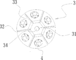
Fig. 4 is the front view of the utility model LED holder structure lamp bracket;
Fig. 5 is the front view of the utility model LED holder structure light cover
The specific embodiment
Below in conjunction with the accompanying drawing and the specific embodiment the utility model LED holder structure is described in further detail:
With reference to Fig. 2, Fig. 3, Fig. 4, a kind of LED holder structure is provided, comprise back cover 1, light cover 2, be installed in the lamp bracket 3 between back cover 1 and the light cover 2, be fixed on 6 LED lamp assemblies 4 on the lamp bracket 3, lamp bracket 3 is a conulite 30, conulite 30 can be multiple-angle pyramid or cone, what present embodiment adopted is multiple-angle pyramid, at the platform 31 of conulite 30 tops formation towards light cover 2, platform 31 is provided with a through hole 34, conulite 30 is separated into 6 fan annular sections 33 by 6 uniform on conical surface breach 32,6 LED lamp assemblies 4 are separately fixed on 6 fan annular sections 33, platform 31 becomes 20 °-70 ° with the conical surface, lamp bracket 3 closely contacts with the outer rim of back cover 1, and both can be aluminium matter or copper member.Be respectively equipped with louvre 10,20 on back cover 1 and the light cover 2.Because lamp bracket 3 is conulite, and closely contact with back cover 1, space between lamp bracket and the back cover is bigger, also be provided with breach 32 on the conulite conical surface, the platform of cone front end is provided with through hole, also is provided with through hole on back cover and the lampshade, formed unobstructed heat dissipation channel, strengthen LED lamp holder heat-sinking capability greatly, thereby effectively guaranteed the luminous efficiency of LED lamp, prolonged the life-span of LED lamp.
With reference to Fig. 5, light cover 2 has the arc shape that cooperates described conulite 30, is evenly equipped with some sandblast bands 21 on it.Sandblast band 21 is that arrange radially at the center with light cover 2 cambered surface tops, and the light that LED lamp assembly sends spills between sandblast band 21 after 21 reflections of sandblast band again, forms soft casual light.
Claims (6)
1. LED holder structure, it is characterized in that, comprise back cover (1), light cover (2), be installed in the lamp bracket (3) between back cover (1) and the light cover (2), be fixed on the lamp bracket if LED lamp assembly (4), described lamp bracket (3) comprises a conulite (30), at the platform (31) of described conulite (30) top formation towards light cover (2), platform (31) is provided with through hole (34), described conulite (30) is separated into some fan annular sections (33) by some breach (32) uniform on the conical surface, described some LED lamp assemblies (4) are separately fixed on described some fan annular sections (33), are respectively equipped with louvre on described back cover (1) and the light cover (2).
2. LED holder structure according to claim 1 is characterized in that, described light cover (2) has the arc shape that cooperates described conulite (30), is evenly equipped with some sandblast bands (21) on it.
3. LED holder structure according to claim 2 is characterized in that, described sandblast band (21) is that arrange radially at the center with light cover (2) cambered surface top.
4. LED holder structure according to claim 1 is characterized in that, described lamp bracket (3) closely contacts with the outer rim of described back cover (1), and both are aluminium matter or copper member.
5. LED holder structure according to claim 1 is characterized in that, platform (31) becomes 20 °-70 ° with the described conical surface.
6. LED holder structure according to claim 1 or 5 is characterized in that described conulite (30) is multiple-angle pyramid or cone.
Priority Applications (1)
| Application Number | Priority Date | Filing Date | Title |
|---|---|---|---|
| CNU2007201219670U CN201081163Y (en) | 2007-08-03 | 2007-08-03 | LED lamp holder structure |
Applications Claiming Priority (1)
| Application Number | Priority Date | Filing Date | Title |
|---|---|---|---|
| CNU2007201219670U CN201081163Y (en) | 2007-08-03 | 2007-08-03 | LED lamp holder structure |
Publications (1)
| Publication Number | Publication Date |
|---|---|
| CN201081163Y true CN201081163Y (en) | 2008-07-02 |
Family
ID=39614835
Family Applications (1)
| Application Number | Title | Priority Date | Filing Date |
|---|---|---|---|
| CNU2007201219670U Expired - Fee Related CN201081163Y (en) | 2007-08-03 | 2007-08-03 | LED lamp holder structure |
Country Status (1)
| Country | Link |
|---|---|
| CN (1) | CN201081163Y (en) |
Cited By (3)
| Publication number | Priority date | Publication date | Assignee | Title |
|---|---|---|---|---|
| CN101832521A (en) * | 2010-04-28 | 2010-09-15 | 海洋王照明科技股份有限公司 | Transparent lamp element and LED lamp |
| CN102427109A (en) * | 2011-10-10 | 2012-04-25 | 郭小华 | Auxiliary part and connecting circuit of light source |
| CN101713525B (en) * | 2008-10-08 | 2012-11-21 | 富准精密工业(深圳)有限公司 | LED indoor lamp and ventilating device using same |
-
2007
- 2007-08-03 CN CNU2007201219670U patent/CN201081163Y/en not_active Expired - Fee Related
Cited By (3)
| Publication number | Priority date | Publication date | Assignee | Title |
|---|---|---|---|---|
| CN101713525B (en) * | 2008-10-08 | 2012-11-21 | 富准精密工业(深圳)有限公司 | LED indoor lamp and ventilating device using same |
| CN101832521A (en) * | 2010-04-28 | 2010-09-15 | 海洋王照明科技股份有限公司 | Transparent lamp element and LED lamp |
| CN102427109A (en) * | 2011-10-10 | 2012-04-25 | 郭小华 | Auxiliary part and connecting circuit of light source |
Similar Documents
| Publication | Publication Date | Title |
|---|---|---|
| CN201363590Y (en) | Large-power LED light source with saturated and gentle light and large-power LED illumination lamp using same | |
| CN201513774U (en) | Internal heat dissipation flower type LED post-shaped lamp | |
| CN202008039U (en) | Big-angle LED lamp tube | |
| CN102095131A (en) | Anti-glare LED (light emitting diode) spotlight | |
| TW200938762A (en) | Assembly of light emitting unit | |
| CN101608785A (en) | LED lamp with combination heat dissipation structure | |
| CN201081163Y (en) | LED lamp holder structure | |
| CN201916737U (en) | LED illuminating lamp and LED illuminating tube | |
| CN203162680U (en) | LED (light emitting diode) illumination lamp | |
| CN202484691U (en) | High-dissipating light-emitting diode (LED) light | |
| CN215259590U (en) | Shine headlight before train | |
| CN202125756U (en) | Omnibearing LED (Light Emitting Diode) lamp | |
| CN201661996U (en) | Reflecting structure for workshop lamps and workshop lamp with the same | |
| WO2009056000A1 (en) | Combined lens and light fixture using the same | |
| CN201983149U (en) | High-power double-light source LED (light-emitting diode) street lamp | |
| CN203585886U (en) | Full-peripheral-light LED bulb lamp | |
| CN203907271U (en) | Ceramic substrate type energy-saving LED bulb | |
| CN202674930U (en) | LED (light-emitting diode) bulb lamp with whole body light emission effect | |
| CN202252979U (en) | Horizontally-inserted type light emitting diode (LED) lamp | |
| CN203115600U (en) | Novel light-emitting diode (LED) lamp | |
| CN101737740A (en) | Shadowless lamp | |
| CN201354955Y (en) | Easy assembled LED spot lamp | |
| CN219082849U (en) | Desk lamp luminescent plate and lamp holder | |
| CN204345556U (en) | A kind of SMD LED component | |
| CN214405689U (en) | Lamp structure convenient for replacing and disassembling optical assembly |
Legal Events
| Date | Code | Title | Description |
|---|---|---|---|
| C14 | Grant of patent or utility model | ||
| GR01 | Patent grant | ||
| C17 | Cessation of patent right | ||
| CF01 | Termination of patent right due to non-payment of annual fee |
Granted publication date: 20080702 Termination date: 20110803 |