CN201070451Y - Breech massager - Google Patents
Breech massager Download PDFInfo
- Publication number
- CN201070451Y CN201070451Y CNU2007200522810U CN200720052281U CN201070451Y CN 201070451 Y CN201070451 Y CN 201070451Y CN U2007200522810 U CNU2007200522810 U CN U2007200522810U CN 200720052281 U CN200720052281 U CN 200720052281U CN 201070451 Y CN201070451 Y CN 201070451Y
- Authority
- CN
- China
- Prior art keywords
- massage
- gear
- motor
- massage head
- buttocks
- Prior art date
- Legal status (The legal status is an assumption and is not a legal conclusion. Google has not performed a legal analysis and makes no representation as to the accuracy of the status listed.)
- Expired - Fee Related
Links
Images

Abstract
The utility model discloses a hip massager, which comprises a controller, as well as a vibration mechanism and a massage-head mechanism which are electrically connected with the controller, wherein, the vibration mechanism consists of a motor and an eccentric block that is connected with the driving shaft of the motor; the massage-head mechanism comprises a motor, a worm rod, a worm gear, a massage gear, a massage shaft and at least one massage head, the driving shaft of the motor is connected with the worm rod, the worm gear is engaged with the worm rod, the massage gear is engaged with the worm gear, one end of the massage shaft is connected with the massage gear, and the other end of the massage shaft is connected with the massage head. Compared with the prior art, the vibration mechanism of the utility model can perform the trembling massage on the hip of the human body, the massage head mechanism can perform the rolling pressing massage on the hip of the human body, and the massage mechanism can produce good massage effect simulating the manual massage, thereby overcoming the weakness of the prior hip massager that the massage way is single and the massage effect simulating the manual massage is poor.
Description
Technical field
This utility model relates to a kind of body-care apparatus, relates in particular to a kind ofly can carry out the buttocks masseur that multiple mode is massaged to the human buttock simultaneously.
Background technology
Along with improving constantly of living standards of the people, corresponding social rhythm and operating pressure also strengthen thereupon, and the people of work need relax the tired out of the pressure of the work of extenuating and health, thereby various body-care apparatus enters into popular family gradually.
At present, massage for the human buttock mainly contains artificial massage and mechanical massage, artificial massage is hand labor, it is bigger that it is influenced by anthropic factor, massage is difficult to be guaranteed qualitatively, and need to the service specified place, and also need specialty the personage can, can not massage anywhere or anytime; And for mechanical massage, the massaging way of existing buttocks masseur is too dull, owes soft in the time of can not realizing the effect of basic massage manipulation and massage work well, does not reach imitation manual massage's effect.
The utility model content
The purpose of this utility model provides a kind of buttocks masseur that has multiple massaging way and can produce manual massage's effect.
For achieving the above object, the technical solution of the utility model is for providing a kind of buttocks masseur, comprise controller and be electrically connected at the vibrating mechanism and the massage head mechanism of controller, described vibrating mechanism is made up of motor and the eccentric block that is connected in motor drive shaft, described massage head mechanism comprises motor, worm screw, worm gear, the massage gear, massaging shaft and at least one massage head, the power transmission shaft of described motor is connected with above-mentioned worm screw, described worm gear and above-mentioned worm engaging, described massage gear and the engagement of above-mentioned worm gear, described massaging shaft one end is connected with above-mentioned massage gear, and the other end is connected with described massage head.
According to a kind of embodiment of the present utility model, described massage head mechanism also comprises transition gear, the number of gears of described transition gear is greater than the number of gears of massage gear, described transition gear one side and the engagement of above-mentioned worm gear, opposite side and above-mentioned massage gears engaged are to regulate the speed that the massage gear rotates.
According to another kind of embodiment of the present utility model, described massage head mechanism also comprises massage bracket, and described massage bracket is connected between described massage head and the massaging shaft.Preferably, described massage head has a plurality of, is installed on the above-mentioned massage bracket, and has different height, thereby realize more large tracts of land and the different massage of weight.
Preferably, massage head mechanism also comprises guard circle utmost point ornament lamp, and described guard circle is used to protect the rotation of massage bracket not to be subjected to the interference of other article outside above-mentioned massage head; Described ornament lamp and above-mentioned controller electrically connect, and when the buttocks masseur was worked, opening ornament lamp simultaneously can increase and show off sense.
This utility model is compared with prior art, vibrating mechanism can carry out the chatter massage to the human buttock, and massage head mechanism can roll to the human buttock and rubs pressing massage, and this massage mechanism can produce extraordinary imitation manual massage's effect, has overcome the defective that current buttocks massage device mode is single and imitate manual massage's weak effect.
For detailed explanation technology contents of the present utility model, structural feature, the purpose that is realized and effect, further illustrate this utility model below in conjunction with the drawings and the specific embodiments.
Description of drawings
Fig. 1 is the three-dimensional combination figure of this utility model buttocks masseur.
Fig. 2 is the three-dimensional exploded view of buttocks masseur shown in Figure 1.
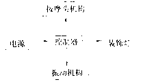
Fig. 3 is the circuit theory diagrams of this utility model buttocks masseur.
Fig. 4 is the three-dimensional exploded view of the vibrating mechanism of buttocks masseur shown in Figure 2.
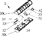
Fig. 5 is the three-dimensional exploded view of the massage head mechanism of buttocks masseur shown in Figure 2.
The specific embodiment
As Fig. 1, Fig. 2 and shown in Figure 3, this utility model buttocks masseur comprises foam 1 and is placed in controller 2, vibrating mechanism 3 and massage head mechanism 5 in the foam 1, described controller 2 electrically connects with the motor of vibrating mechanism 3 and massage head mechanism 5 respectively, be used to control the work of vibrating mechanism 3 and massage head mechanism 5, described vibrating mechanism 3 is placed in the vibration area 10 of foam 1, described massage head mechanism 5 is placed in the massaged region 11 of foam 1, and described controller 2 is placed in the control area 12 of foam 1.
Please cooperate and consult Fig. 2 and Fig. 4, the vibration of described vibrating mechanism 3 is to drive the eccentric block 32 that is connected on motor 31 power transmission shafts 33 by motor 31 to realize that described motor 31 and eccentric 32 thereof are contained in by in motor lower carriage 30a and the formed space of motor upper bracket 30b.More specifically, the upper and lower support 30a of described motor, 30b are the bathtub construction of cross section semicircular in shape, and inwall is provided with some supports 34, and the upper and lower support 30a of motor, 30b fasten the cylinder that a hollow is formed in the back in a conventional manner.Described vibrating mechanism 3 comprises two groups of motors 3 and eccentric block 32, and these two groups of motors 31 and eccentric block 32 are distributed in cylindrical two ends, and is carried on the corresponding support 34.Certainly the group number and the layout type of motor and eccentric block are not limited thereto, and can select as required.
Please cooperate and consult Fig. 2 and Fig. 5, described massage head mechanism 5 comprises motor 50, motor lower fixed frame 52a, motor upper holder 52b, worm screw 51, worm gear 53, transition gear 54, massage gear 55, massaging shaft 56, massage bracket 58 and massage head 57a, 57b.Described worm gear 53, massage gear 54, transition gear 54 and massaging shaft 56 are installed between motor lower fixed frame 52a and the motor upper holder 52b, and described massaging shaft 56 and massage head 57a, 57b reach outside the motor upper holder 52b.More specifically, the power transmission shaft 500 of described motor 50 is connected with above-mentioned worm screw 51, described worm gear 53 be distributed in above-mentioned worm screw 51 1 sides and with its engagement, on the described worm gear 53 rotating pillars 521 that are connected on the motor lower fixed frame 52a, described transition gear 54 is between above-mentioned worm gear 53 and massage gear 55 and on the rotating pillar 522 that is connected on the motor lower fixed frame, motor upper holder 52b is placed on the said motor lower fixed frame 52a, described massaging shaft 56 1 ends are connected with above-mentioned massage gear 55, the other end passes said motor upper holder 52b and is connected on the support connecting hole 580 of described massage bracket 58, and massaging shaft 56 and massage bracket 58 can be rotated with massage gear 55 like this.Described massage head 57a is connected on the pillar 58a of massage bracket 58, and described massage head 57b is connected on the pillar 58b of massage bracket 58, and described massage head 57a, 57b are distributed in the both sides of the support connecting hole 580 of above-mentioned massage bracket 58.Driving worm screw 51 when motor 50 is driven rotates, described worm screw 51 drives the worm gear 53 with its engagement again, the rotation of above-mentioned worm gear 53 drives the transition gear 54 with its engagement again, described transition gear 54 drives the massage gear 55 with its engagement again, driving massage bracket 58 by above-mentioned massage gear 55 by massaging shaft 56 again rotates, massage head 57a, 57b that the rotation of described massage bracket 58 drives around the support connecting hole 580 that is distributed in massage bracket 58 again rotate, thereby the realization massage head is done circumference and is rolled, and realizes the effect that pressing massage is rubbed in the artificial rolling of imitation.Alternatively, if massage head has only one, can omit massage bracket, and massaging shaft is designed to bent axle, massage head is directly connected in bent axle massage the tip of the axis, and so same energy makes the massage head that connects thereon do the circumference rolling, thereby realizes the artificial effect of rolling and rubbing pressing massage of imitation.
The preferably, as shown in Figure 5, the number of gears of described transition gear 54 is greater than the number of gears of massage gear 55, described transition gear 54 1 sides and 53 engagements of above-mentioned worm gear, opposite side and 55 engagements of above-mentioned massage gear, play the effect that massage gear 55 rotates speed of regulating, thereby be adjusted to the effect that the massage head 57a, the 57b that are driven by massage gear 55 rotate speed, certainly, if need not regulate the rotating speed of massage gear 55, then transition gear 54 can omit, and directly is engaged in worm gear 53 and will massage gear 55.The described massage bracket 58 of described massage head mechanism 5 is mainly used in and connects a plurality of massage head, and described massage head is distributed in around the support connecting hole 580 of massage bracket 58, rotates together, realizes more large-area massage effect.Described massage head mechanism 5 also comprises guard circle 59, and described guard circle 59 is used to protect the rotation of massage bracket 58 not to be subjected to the interference of other article, thereby guarantees the normal operation of massage head 57a, 57b outside above-mentioned massage bracket 58; Thereby described massage head 57a, 57b have different height to be formed to the human body weight different rollings and rubs pressure, makes the better effects if of imitating body massaging like this; More specifically, described massage head mechanism comprises two groups of worm gears 53, transition gear 54, massage gear 55, massaging shaft 56, massage bracket 58 and massage head 57a, 57b, and these two groups are symmetrically distributed in worm screw 51 both sides.Certainly, group number and the layout type of the worm gear 53 in the massage head mechanism, transition gear 54, massage gear 55, massaging shaft 56, massage bracket 58 and massage head 57a, 57b are not limited thereto, and can select as required.
This utility model buttocks masseur also comprises ornament lamp 4, described ornament lamp 4 is installed on the said motor upper holder 52b, and be connected with above-mentioned controller electricity 2 property, when the buttocks masseur is worked, open the sense of showing off that ornament lamp 4 can increase this utility model buttocks masseur simultaneously.
In conjunction with Fig. 2 and Fig. 3, the work process of this utility model buttocks masseur is done a detailed explanation, vibrating mechanism 3 of the present utility model, massage head mechanism 5 and ornament lamp 4 electrically connect with controller 2 respectively, controller 2 provides power supply by external power, controller 2 is used for controlling the duty of vibrating mechanism 3, massage head mechanism 5 and ornament lamp 4, as control above-mentioned vibrating mechanism 3, massage head mechanism 5 and ornament lamp 4 and work simultaneously and also can make its single work or work simultaneously in twos, can also control the frequency of vibration or the pattern of vibrating mechanism 3.
Vibrating mechanism in this utility model can carry out the chatter massage to the human buttock, and massage head mechanism can roll to the human buttock and rubs pressing massage, and this massage mechanism can produce extraordinary imitation manual massage's effect, has overcome the defective that current buttocks massage device mode is single and imitate manual massage's weak effect.
Above disclosed only is preferred embodiment of the present utility model, can not limit the interest field of this utility model certainly with this, and therefore the equivalent variations of being done according to this utility model claim still belongs to the scope that this utility model is contained.
Claims (10)
1. buttocks masseur, it is characterized in that, comprise controller and be electrically connected at the vibrating mechanism and the massage head mechanism of controller, described vibrating mechanism is made up of motor and the eccentric block that is connected in motor drive shaft, described massage head mechanism comprises motor, worm screw, worm gear, massage gear, massaging shaft and at least one massage head, the power transmission shaft of described motor is connected with above-mentioned worm screw, described worm gear and above-mentioned worm engaging, described massage gear and the engagement of above-mentioned worm gear, described massaging shaft one end is connected with above-mentioned massage gear, and the other end is connected with described massage head.
2. buttocks masseur as claimed in claim 1 is characterized in that, described massage head mechanism also comprises transition gear, described transition gear one side and the engagement of above-mentioned worm gear, opposite side and above-mentioned massage gears engaged.
3. buttocks masseur as claimed in claim 2 is characterized in that, the number of gears of described transition gear is greater than the number of gears of massage gear.
4. buttocks masseur as claimed in claim 1 is characterized in that, described massage head mechanism also comprises massage bracket, and described massage bracket is connected between above-mentioned massage head and the massaging shaft.
5. buttocks masseur as claimed in claim 4 is characterized in that described massage head has a plurality of, is installed on the described massage bracket, and has different height.
6. buttocks masseur as claimed in claim 1 is characterized in that, described massage head mechanism also comprises guard circle, and described guard circle is outside above-mentioned massage head.
7. buttocks masseur as claimed in claim 1 is characterized in that, also comprises ornament lamp, and described ornament lamp and above-mentioned controller electrically connect.
8. buttocks masseur as claimed in claim 1, it is characterized in that, described massage head mechanism also comprises motor lower fixed frame and motor upper holder, described worm screw, worm gear, massage gear and massaging shaft are installed between motor lower fixed frame and the motor upper holder, and described massaging shaft and massage head reach outside the motor upper holder.
9. buttocks masseur as claimed in claim 1 is characterized in that, vibrating mechanism also comprises motor upper bracket and motor lower carriage, and the motor of described vibrating mechanism and eccentric block are housed in motor lower carriage and the formed space of motor upper bracket.
10. buttocks masseur as claimed in claim 1 is characterized in that, also comprises foam, and described controller, vibrating mechanism and massage head mechanism all are placed in the foam.
Priority Applications (2)
| Application Number | Priority Date | Filing Date | Title |
|---|---|---|---|
| CNU2007200522810U CN201070451Y (en) | 2007-06-01 | 2007-06-01 | Breech massager |
| JP2008002286U JP3142665U (en) | 2007-06-01 | 2008-04-10 | Buttocks massager |
Applications Claiming Priority (1)
| Application Number | Priority Date | Filing Date | Title |
|---|---|---|---|
| CNU2007200522810U CN201070451Y (en) | 2007-06-01 | 2007-06-01 | Breech massager |
Publications (1)
| Publication Number | Publication Date |
|---|---|
| CN201070451Y true CN201070451Y (en) | 2008-06-11 |
Family
ID=39549007
Family Applications (1)
| Application Number | Title | Priority Date | Filing Date |
|---|---|---|---|
| CNU2007200522810U Expired - Fee Related CN201070451Y (en) | 2007-06-01 | 2007-06-01 | Breech massager |
Country Status (2)
| Country | Link |
|---|---|
| JP (1) | JP3142665U (en) |
| CN (1) | CN201070451Y (en) |
Cited By (6)
| Publication number | Priority date | Publication date | Assignee | Title |
|---|---|---|---|---|
| CN105105967A (en) * | 2015-09-22 | 2015-12-02 | 苏州春天印象健身器材有限公司 | Hip massaging frame and massaging chair with same |
| CN106562874A (en) * | 2015-10-13 | 2017-04-19 | 陈观喜 | Massager of rolling-kneading type |
| CN106580655A (en) * | 2015-10-15 | 2017-04-26 | 陈闺艳 | Meridian dredging therapeutic machine |
| CN106580656A (en) * | 2015-10-15 | 2017-04-26 | 陈闺艳 | Vibration-type health-care massage device by utilizing magnetic therapy |
| CN106619006A (en) * | 2015-11-03 | 2017-05-10 | 周保国 | Novel exercise fitness equipment |
| CN108309725A (en) * | 2016-06-23 | 2018-07-24 | 泉州泉港灿鹏机械设备有限公司 | A kind of buttocks massage robot |
Families Citing this family (1)
| Publication number | Priority date | Publication date | Assignee | Title |
|---|---|---|---|---|
| CN111714357B (en) * | 2020-07-08 | 2022-06-21 | 张爽 | Beauty treatment stick |
-
2007
- 2007-06-01 CN CNU2007200522810U patent/CN201070451Y/en not_active Expired - Fee Related
-
2008
- 2008-04-10 JP JP2008002286U patent/JP3142665U/en not_active Expired - Fee Related
Cited By (7)
| Publication number | Priority date | Publication date | Assignee | Title |
|---|---|---|---|---|
| CN105105967A (en) * | 2015-09-22 | 2015-12-02 | 苏州春天印象健身器材有限公司 | Hip massaging frame and massaging chair with same |
| CN106562874A (en) * | 2015-10-13 | 2017-04-19 | 陈观喜 | Massager of rolling-kneading type |
| CN106580655A (en) * | 2015-10-15 | 2017-04-26 | 陈闺艳 | Meridian dredging therapeutic machine |
| CN106580656A (en) * | 2015-10-15 | 2017-04-26 | 陈闺艳 | Vibration-type health-care massage device by utilizing magnetic therapy |
| CN106619006A (en) * | 2015-11-03 | 2017-05-10 | 周保国 | Novel exercise fitness equipment |
| CN108309725A (en) * | 2016-06-23 | 2018-07-24 | 泉州泉港灿鹏机械设备有限公司 | A kind of buttocks massage robot |
| CN108309725B (en) * | 2016-06-23 | 2020-12-11 | 浙江昌新生物纤维股份有限公司 | Hip massage robot |
Also Published As
| Publication number | Publication date |
|---|---|
| JP3142665U (en) | 2008-06-19 |
Similar Documents
| Publication | Publication Date | Title |
|---|---|---|
| CN201070451Y (en) | Breech massager | |
| CN204521478U (en) | Leg massor | |
| CN201108569Y (en) | Massage device for cervix and shoulder | |
| CN208809003U (en) | Chinese medicine the five internal organs navel treats massage device | |
| CN203425212U (en) | Massager | |
| CN107028746A (en) | Appliance for personal care with advanced features | |
| CN106389096A (en) | Vibrating type magnetic therapy health care massaging apparatus | |
| CN106389094A (en) | Personal care equipment having advanced features | |
| CN201267600Y (en) | Massaging and kneading mechanism | |
| CN204863920U (en) | A neck, shoulder and back massage appearance for house endowment | |
| CN201551514U (en) | Multifunctional music massage cushion | |
| CN201182726Y (en) | Reciprocating type back massage device | |
| CN106691807A (en) | Automatic reduction type ejection percussion massager | |
| CN202446460U (en) | Novel portable massage pillow | |
| KR200462748Y1 (en) | Buttocks massage device | |
| CN2699872Y (en) | Massager for shoulders and knees | |
| CN204562819U (en) | Lower limb rehabilitation physiotherapy table | |
| CN202446458U (en) | Circulating back massager | |
| CN106562876A (en) | Human massaging simulation system | |
| CN106963613A (en) | A kind of portable eye massage machine | |
| CN106562874A (en) | Massager of rolling-kneading type | |
| CN106691808A (en) | Headstock eccentric driving structure of massager | |
| CN106618990A (en) | Neck and shoulder massager | |
| CN106618989A (en) | Waist and hip massage device | |
| CN202005870U (en) | Neck massager |
Legal Events
| Date | Code | Title | Description |
|---|---|---|---|
| C14 | Grant of patent or utility model | ||
| GR01 | Patent grant | ||
| C17 | Cessation of patent right | ||
| CF01 | Termination of patent right due to non-payment of annual fee |
Granted publication date: 20080611 Termination date: 20130601 |