CN201055122Y - Household shoe cabinet - Google Patents
Household shoe cabinet Download PDFInfo
- Publication number
- CN201055122Y CN201055122Y CNU2007200232771U CN200720023277U CN201055122Y CN 201055122 Y CN201055122 Y CN 201055122Y CN U2007200232771 U CNU2007200232771 U CN U2007200232771U CN 200720023277 U CN200720023277 U CN 200720023277U CN 201055122 Y CN201055122 Y CN 201055122Y
- Authority
- CN
- China
- Prior art keywords
- cabinet
- connection rod
- rod set
- pedal
- door
- Prior art date
- Legal status (The legal status is an assumption and is not a legal conclusion. Google has not performed a legal analysis and makes no representation as to the accuracy of the status listed.)
- Expired - Fee Related
Links
Images


Abstract
The utility model provides a household shoe cabinet, which comprises a manually operated door (2), a cabinet body (10) and door side boards (11). The utility model is characterized in that a flexibly connected pedal (9) is arranged outside on one side on the lower end of the cabinet body (10); the pedal (9) is connected with a link rod group (7) through a shaft (8); the link rod group (7) is permanently connected with a foot operated door (5); the link rod group (7) is permanently connected with a door base plate (16) at the bottom of the cabinet body (10). Accordingly, the utility model has simple structure, is timesaving, labor-saving, usable and is in particular applicable for placement of shoes.
Description
Technical field:
The utility model relates to a kind of shoe chest, particularly a kind of family expenses shoe chest.
Background technology:
At present, the family expenses shoe chest adopts more to be destroyed behind the body of wall by decoration worker's simpler production or adopts methods such as placing shoe rack, not only not attractive in appearance, also can destroy wall body structure, for the shoes of shoe chest bottom, all will bend over when putting wearing, and brings inconvenience.
Summary of the invention:
The purpose of this utility model just provides a kind of simple in structure, and is time saving and energy saving, family expenses shoe chest easy to use.
The purpose of this utility model is achieved in that a kind of family expenses shoe chest, form by manually operated door (2), cabinet (10), reveal plate (11), a side peripheral hardware that it is characterized in that described cabinet (10) lower end flexibly connects pedal (9), pedal (9) connects connection rod set (7) by axle (8), connection rod set (7) is fixedlyed connected with foot-operated door (5), and connection rod set (7) is fixedlyed connected with cabinet (10) bottom door base plate (16) by spring (14).
An optimum implementation of the present utility model is:
Solid footwear glue rope (3) is installed between the reveal plate (11), and connection rod set (7) is 3 connecting rods (15) to be arranged by pin II (13) composition that links together.
The utility model compared with prior art has following characteristics:
Owing to adopted a side peripheral hardware of cabinet (10) lower end to flexibly connect pedal (9), pedal (9) connects connection rod set (7) by axle (8), connection rod set (7) is fixedlyed connected with foot-operated door (5), the frame mode that connection rod set (7) is connected with cabinet (10) bottom door base plate (16) by spring (14), thereby have simple in structure, time saving and energy saving, characteristics such as easy to use.
Description of drawings:
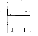
Fig. 1 is a structural representation of the present utility model.
Fig. 2 is the generalized section of Fig. 1.
Fig. 3 is an opening schematic diagram of the present utility model.
1, handle 2, manually operated door 3, solid footwear glue rope 4, dividing plate 5, foot-operated door 6, solid footwear glue rope 7, connection rod set 8, axle 9, pedal 10, cabinet 11, reveal plate 12, pin I 13, pin II 14, spring 15, connecting rod 16, door base plate
The specific embodiment;
Shoe chest described in the utility model is made by plank, the top of cabinet (10) is manually operated door (2), manually operated door (2) is gone up fixedly connected handle (1), the below of cabinet (10) is foot-operated door (5), be provided with dividing plate (4) between two-layer up and down, each fixedlys connected a reveal plate (11) and a door base plate (16) manually operated door (2) and foot-operated door (5), reveal plate (11) is gone up fixedly connected solid footwear glue rope (6) or solid footwear glue rope (3), the fixedly connected pin I in the below of reveal plate (11) (12), pedal (9) connects connection rod set (7) by axle (8), connection rod set (7) is to have 3 connecting rods (15) to link together by pin (13), and connection rod set (7) is connected with cabinet (10) bottom door base plate (16) by spring (14).
During use, the pedal that tramps with one's feet down (9), foot-operated door (5) automatically springs open, promptly interchangeable footwear, finish change the footwear action after, push down on the pedal (9) reset and get final product again, the shoes of often wearing are put into foot-operated (5), the shoes of often not wearing are put into manually operated door (2).
Claims (3)
1. family expenses shoe chest, form by manually operated door (2), cabinet (10), reveal plate (11), a side peripheral hardware that it is characterized in that described cabinet (10) lower end flexibly connects pedal (9), pedal (9) connects connection rod set (7) by axle (8), connection rod set (7) is fixedlyed connected with foot-operated door (5), and connection rod set (7) is fixedlyed connected with cabinet (10) bottom door base plate (16) by spring (14).
2. family expenses shoe chest according to claim 1 is characterized in that being equipped with between the described reveal plate (11) solid footwear glue rope (3).
3. family expenses shoe chest according to claim 1 and 2 is characterized in that described connection rod set (7) is 3 connecting rods (15) to be arranged by pin (13) composition that links together.
Priority Applications (1)
| Application Number | Priority Date | Filing Date | Title |
|---|---|---|---|
| CNU2007200232771U CN201055122Y (en) | 2007-06-14 | 2007-06-14 | Household shoe cabinet |
Applications Claiming Priority (1)
| Application Number | Priority Date | Filing Date | Title |
|---|---|---|---|
| CNU2007200232771U CN201055122Y (en) | 2007-06-14 | 2007-06-14 | Household shoe cabinet |
Publications (1)
| Publication Number | Publication Date |
|---|---|
| CN201055122Y true CN201055122Y (en) | 2008-05-07 |
Family
ID=39423964
Family Applications (1)
| Application Number | Title | Priority Date | Filing Date |
|---|---|---|---|
| CNU2007200232771U Expired - Fee Related CN201055122Y (en) | 2007-06-14 | 2007-06-14 | Household shoe cabinet |
Country Status (1)
| Country | Link |
|---|---|
| CN (1) | CN201055122Y (en) |
Cited By (1)
| Publication number | Priority date | Publication date | Assignee | Title |
|---|---|---|---|---|
| CN105059663A (en) * | 2015-07-24 | 2015-11-18 | 四川金锋建设有限公司 | Rapidly foldable storage box |
-
2007
- 2007-06-14 CN CNU2007200232771U patent/CN201055122Y/en not_active Expired - Fee Related
Cited By (1)
| Publication number | Priority date | Publication date | Assignee | Title |
|---|---|---|---|---|
| CN105059663A (en) * | 2015-07-24 | 2015-11-18 | 四川金锋建设有限公司 | Rapidly foldable storage box |
Similar Documents
| Publication | Publication Date | Title |
|---|---|---|
| USD591031S1 (en) | Shoe | |
| CN201055122Y (en) | Household shoe cabinet | |
| CN204888873U (en) | Convenient indoor outdoor shoes of wearing | |
| CN203262967U (en) | Shoehorn machine capable of enabling people not to bend down | |
| CN205781847U (en) | A kind of Novel photographic equipment support bar | |
| CN204861426U (en) | Equipment shoes | |
| CN201409508Y (en) | Slipper with hook | |
| CN202086406U (en) | Pedal reciprocating type toilet sealing cover | |
| CN205234203U (en) | Bedroom clothing couple | |
| CN201252984Y (en) | Pedal switching type shoes cupboard | |
| CN201474198U (en) | Stair | |
| CN2901935Y (en) | Slippers with detachable vamps | |
| CN201403610Y (en) | Shoe tree | |
| CN204364854U (en) | A kind of pair sticks up slide plate | |
| CN202233978U (en) | Basketball placing frame | |
| CN201295971Y (en) | High-low position dual-purpose horizontal splitter | |
| CN204378465U (en) | A kind of connection structure of frame on bathroom cabinet | |
| CN205967189U (en) | Two -way dotter | |
| CN206482134U (en) | Hand zipper puller assembly machine structure | |
| CN201171398Y (en) | Wireless sewing connection structure of footwear upper | |
| CN209594578U (en) | The Collapsible mobile of brake device fishes platform | |
| CN201888666U (en) | Novel stool | |
| CN207194712U (en) | A kind of new aluminium section bar that can quickly connect | |
| CN207343199U (en) | A kind of anchor pole coating decoration overturns frock | |
| CN206860716U (en) | A kind of ship windlass brake block |
Legal Events
| Date | Code | Title | Description |
|---|---|---|---|
| C14 | Grant of patent or utility model | ||
| GR01 | Patent grant | ||
| C19 | Lapse of patent right due to non-payment of the annual fee | ||
| CF01 | Termination of patent right due to non-payment of annual fee |