CN201014751Y - Waste heat recovery gas water heater for waste water - Google Patents
Waste heat recovery gas water heater for waste water Download PDFInfo
- Publication number
- CN201014751Y CN201014751Y CNU2007200475523U CN200720047552U CN201014751Y CN 201014751 Y CN201014751 Y CN 201014751Y CN U2007200475523 U CNU2007200475523 U CN U2007200475523U CN 200720047552 U CN200720047552 U CN 200720047552U CN 201014751 Y CN201014751 Y CN 201014751Y
- Authority
- CN
- China
- Prior art keywords
- waste
- water
- heat exchanger
- heat recovery
- gas
- Prior art date
- Legal status (The legal status is an assumption and is not a legal conclusion. Google has not performed a legal analysis and makes no representation as to the accuracy of the status listed.)
- Expired - Fee Related
Links
Images


Classifications
-
- Y—GENERAL TAGGING OF NEW TECHNOLOGICAL DEVELOPMENTS; GENERAL TAGGING OF CROSS-SECTIONAL TECHNOLOGIES SPANNING OVER SEVERAL SECTIONS OF THE IPC; TECHNICAL SUBJECTS COVERED BY FORMER USPC CROSS-REFERENCE ART COLLECTIONS [XRACs] AND DIGESTS
- Y02—TECHNOLOGIES OR APPLICATIONS FOR MITIGATION OR ADAPTATION AGAINST CLIMATE CHANGE
- Y02B—CLIMATE CHANGE MITIGATION TECHNOLOGIES RELATED TO BUILDINGS, e.g. HOUSING, HOUSE APPLIANCES OR RELATED END-USER APPLICATIONS
- Y02B30/00—Energy efficient heating, ventilation or air conditioning [HVAC]
Landscapes
- Instantaneous Water Boilers, Portable Hot-Water Supply Apparatuses, And Control Of Portable Hot-Water Supply Apparatuses (AREA)
Abstract
本实用新型公开了一种废水余热回收燃气热水器,包括由燃烧器、点火装置、控制系统和主热交换器及外壳体、冷水进水管路、热水出水管路组成的热水器主体,燃烧室、主热交换器均处于一密闭室内,密闭室并连通有排烟气通道及出口,其特征在于,在主热交换器的上方的排烟气通道中还设置有另一废气余热回收热交换器构成冷凝式燃气热水器,在冷水进水管路中还设置有一废水余热回收热交换器,废水余热回收热交换器设置在燃气热水器的热水出口下方,冷水进水管路经废水余热回收热交换器后连接废气余热回收热交换器,再连接燃气主热交换器。本实用新型具有结构简单合理、热利用效率高等优点。
The utility model discloses a waste water waste heat recovery gas water heater, which comprises a water heater body composed of a burner, an ignition device, a control system, a main heat exchanger and an outer casing, a cold water inlet pipeline, and a hot water outlet pipeline, a combustion chamber, The main heat exchangers are all located in a closed room, and the closed room is connected with a flue gas passage and an outlet. It is characterized in that another exhaust gas waste heat recovery heat exchanger is arranged in the flue gas passage above the main heat exchanger. To form a condensing gas water heater, there is also a waste heat recovery heat exchanger in the cold water inlet pipeline. The waste heat recovery heat exchanger is arranged below the hot water outlet of the gas water heater. Connect the exhaust gas waste heat recovery heat exchanger, and then connect the gas main heat exchanger. The utility model has the advantages of simple and reasonable structure, high heat utilization efficiency and the like.
Description
技术领域 technical field
本实用新型涉及一种热水器,更具体地说是涉及一种对废水余热进行回收、提高热利用效率的热水器。The utility model relates to a water heater, in particular to a water heater which recovers waste heat from waste water and improves heat utilization efficiency.
背景技术 Background technique
传统的热水器在使用过程中,燃气热水器产生的高温烟气在经热交换器交换后,温度仍然较高,可达150~200℃,经计算10%以上的热量随烟气而排放走,另一方面,经使用后的废热水的热量也是白白浪费,没有得以更好地利用。为了降低排烟温度并回收烟气中的热量利用,人们发明了冷凝式燃气热水器,但如何回收利用废热水的热量,暂时还未解决。During the use of traditional water heaters, the temperature of the high-temperature flue gas generated by gas water heaters is still high after being exchanged by the heat exchanger, which can reach 150-200°C. It is calculated that more than 10% of the heat will be discharged with the flue gas. On the one hand, the heat of the used waste hot water is also wasted and not better utilized. In order to reduce the exhaust gas temperature and recover the heat in the flue gas, people have invented a condensing gas water heater, but how to recover and utilize the heat of the waste hot water has not yet been resolved.
实用新型内容Utility model content
本实用新型的目的就是为了解决上述之不足,而提供一种可对废水余热进行回收利用的废水余热回收燃气热水器。The purpose of this utility model is to solve the above-mentioned deficiencies, and provide a waste water waste heat recovery gas water heater which can recycle waste water waste heat.
本实用新型为了达到上述目的而采取的技术解决方案如下:The technical solution that the utility model takes in order to achieve the above object is as follows:
一种废水余热回收燃气热水器,包括由燃烧器、点火装置、控制系统和主热交换器及外壳体、冷水进水管路、热水出水管路组成的热水器主体,燃烧室、主热交换器均处于一密闭室内,密闭室并连通有排烟气通道及出口,其特征在于,在主热交换器的上方的排烟气通道中还设置有另一废气余热回收热交换器构成冷凝式燃气热水器,在冷水进水管路中还设置有一废水余热回收热交换器,废水余热回收热交换器设置在燃气热水器的热水出口下方,冷水进水管路经废水余热回收热交换器后连接废气余热回收热交换器,再连接燃气主热交换器。A waste water waste heat recovery gas water heater, including a water heater body consisting of a burner, an ignition device, a control system, a main heat exchanger and an outer casing, a cold water inlet pipeline, and a hot water outlet pipeline, the combustion chamber and the main heat exchanger are both It is located in a closed room, and the closed room is connected with a flue gas passage and an outlet. It is characterized in that another exhaust gas waste heat recovery heat exchanger is arranged in the flue gas passage above the main heat exchanger to form a condensing gas water heater. , there is also a waste heat recovery heat exchanger in the cold water inlet pipeline, the waste heat recovery heat exchanger is set under the hot water outlet of the gas water heater, and the cold water inlet pipeline is connected to the waste gas waste heat recovery heat exchanger after passing through the waste water waste heat recovery heat exchanger exchanger, and then connected to the gas main heat exchanger.
所述废气余热回收热交换热器表面采用不锈钢或铝合金材料,表面设有防止酸性腐蚀的保护层。The surface of the exhaust gas waste heat recovery heat exchanger is made of stainless steel or aluminum alloy, and the surface is provided with a protective layer to prevent acid corrosion.
所述废气余热回收热交换热器下方设置有冷凝水收集装置,冷凝水收集装置连通有冷凝水排水管。A condensed water collection device is arranged below the exhaust gas waste heat recovery heat exchanger, and the condensed water collection device is connected with a condensed water drain pipe.
所述废水余热回收热交换器安装在支承架内,支承架上设带有漏水孔的支撑板,下部设有废水出口构成废水余热回收热交换装置。The heat exchanger for waste heat recovery from waste water is installed in a support frame, and a support plate with water leakage holes is arranged on the support frame, and a waste water outlet is provided at the lower part to form a waste heat recovery heat exchange device for waste water.
本实用新型采用上述技术解决方案所能达到的有益效果是:The beneficial effect that the utility model can reach by adopting above-mentioned technical solution is:
1.采用常规的燃烧形式,将热交换器设置在燃烧室的上方,使火焰向上燃烧有利于火焰稳定控制;1. Adopt the conventional combustion form, and set the heat exchanger above the combustion chamber, so that the flame burns upwards, which is conducive to the stable control of the flame;
2.在层状式设置的热交换器下再设置冷凝水收集装置,可有效地保护热交换器被呈酸性的冷凝水腐蚀;2. Install a condensed water collection device under the layered heat exchanger, which can effectively protect the heat exchanger from being corroded by acidic condensed water;
3.冷水依次通过废气余热热交换器与废水余热回收换热装置,与热烟气和热水逆流两次换热,充分吸收燃气燃烧所产生的废气热量及废热水热量,预热后进入热水器,从而大幅度的提高了热利用效率;3. The cold water passes through the exhaust gas waste heat heat exchanger and the waste water waste heat recovery heat exchange device in turn, and exchanges heat with the hot flue gas and hot water countercurrently twice, fully absorbs the heat of the waste gas and the heat of the waste hot water generated by the combustion of gas, and enters after preheating Water heater, thus greatly improving the heat utilization efficiency;
4.本实用新型采用风机进行强制给排烟气方式,安全可靠。4. The utility model adopts the method of forced supply and exhaust of smoke by fan, which is safe and reliable.
附图说明 Description of drawings
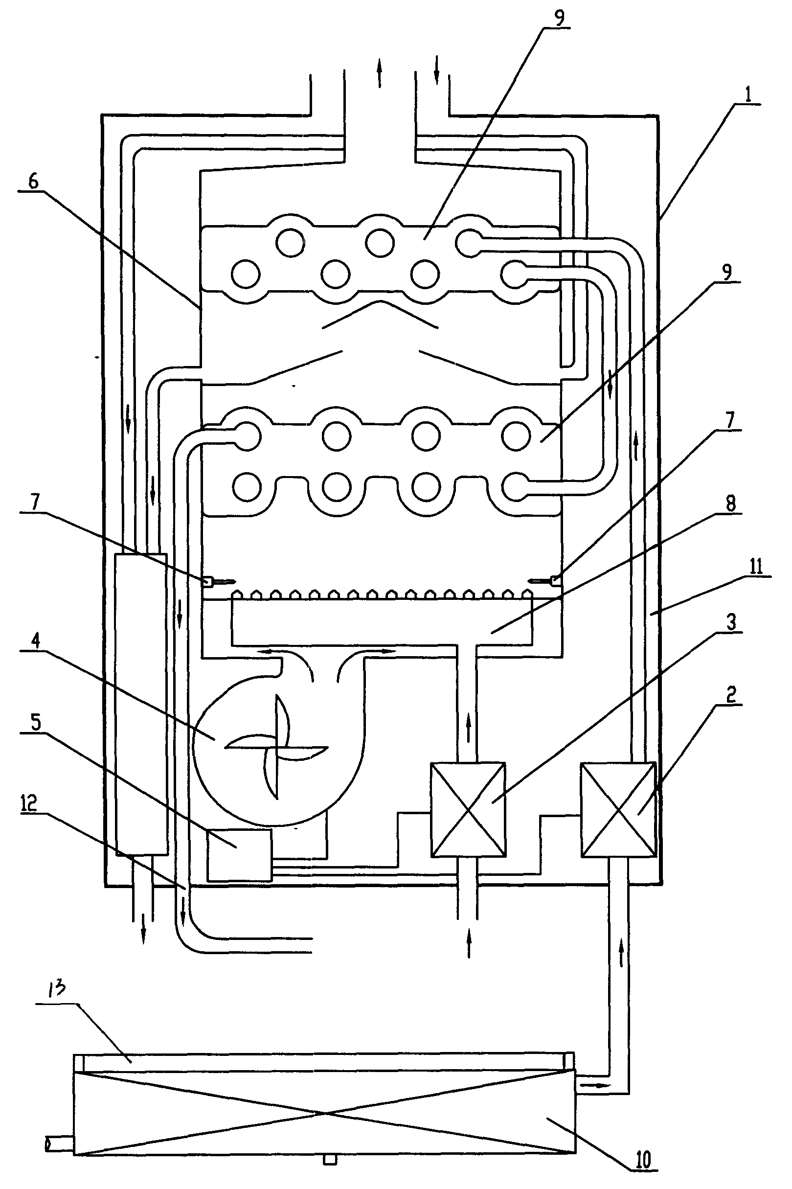
图1为本实用新型的结构示意图;Fig. 1 is the structural representation of the utility model;
图2为本实用新型的使用连接示意图;Fig. 2 is the use connection schematic diagram of the utility model;
图3为本实用新型的废水余热回收装置外观结构示意图;Fig. 3 is a schematic diagram of the appearance structure of the wastewater waste heat recovery device of the present invention;
图4为本实用新型的废水余热回收装置的传热原理示意图。Fig. 4 is a schematic diagram of the heat transfer principle of the wastewater waste heat recovery device of the present invention.
附图标记说明:外壳1、水阀2、气阀3、风机4、控制系统5、燃烧室6、点火装置7、燃烧器8、热交换器9、废水余热回收热交换器10、进水管11、排水管12、支撑板13。Explanation of reference numerals: shell 1, water valve 2, air valve 3, fan 4, control system 5, combustion chamber 6, ignition device 7, burner 8, heat exchanger 9, waste water waste heat
具体实施方式 Detailed ways
由图1所示,该废水余热回收燃气热水器,包括外壳1以及安装在外壳1内的水阀2、气阀3、风机4、控制系统5、燃烧室6、点火装置7、燃烧器8和热交换器9,点火装置7是点火电极,所述气阀3是比例阀,所述燃烧器8设置在燃烧室6的内侧底部,风机4与燃烧室6的底部开口连通,通过气阀3和风机4提供燃烧所需的燃气和空气,热交换器9也设置在燃烧室6内且位于燃烧器8的上方,热交换器9是由呈层状设置的二个换热器组成,换热器间通过水管连通,在两个换热器间设置有冷凝水收集装置及冷凝水排水管道14,气阀3通过气管与燃烧器8连通,水阀2通过进水管11与热交换器9的上层换热器的进水口连通,热交换器9的下层换热器的出水口与排水管12连通,在热交换器9的表面设有防止冷凝水酸性腐蚀的保护层,所述进水管11连接设置一废水余热回收热交换器10,排水管12的热水出口位于废水余热回收换热装置的上方,废水余热回收换热装置主要由热交换器10、支撑板13组成,采用板式换热原理,四周采用聚脂塑料做支承架,支撑板13设置在热交换器的上方,其上设置有漏水孔,使用后的废水流向废水余热回收热交换器10内,与经过该换热装置的清洁冷水发生热交换,预热后的冷水正式进入热水器内加热,有效利用了热量,里面的冷水与外面的废水独立分流,只发生热对流,而不会互相渗透,对使用没有任何影响;所述废水余热回收热交换器10表面为防锈层,下部设置有废水出口,多余的废水可以在换热后流走;所述废气余热回收热交换热器10下方设置有冷凝水收集装置。点火装置7设置在燃烧器8旁的外壳1一上,用于向燃烧器8提供火源,水阀2、气阀3和风机4与控制系统5电连接,在点火装置7放电后燃烧时,控制系统5根据设置的水温,调节气阀3的燃气量与空气量的进入比例,保证燃烧能够更加充分,上述的冷凝水收集装置最好采用不锈钢的耐酸性材料制作,冷凝水收集装置与冷凝水排水管连通。As shown in Figure 1, the waste water waste heat recovery gas water heater includes a casing 1 and a water valve 2 installed in the casing 1, a gas valve 3, a fan 4, a control system 5, a combustion chamber 6, an ignition device 7, a burner 8 and The heat exchanger 9, the ignition device 7 is an ignition electrode, the gas valve 3 is a proportional valve, the burner 8 is arranged on the inner bottom of the combustion chamber 6, the fan 4 communicates with the bottom opening of the combustion chamber 6, and the gas valve 3 The gas and air required for combustion are provided by the blower fan 4. The heat exchanger 9 is also arranged in the combustion chamber 6 and above the burner 8. The heat exchanger 9 is composed of two heat exchangers arranged in layers. The heat exchangers are connected through water pipes, and a condensed water collection device and a condensed water drainage pipe 14 are installed between the two heat exchangers. The gas valve 3 is connected with the burner 8 through the gas pipe, and the water valve 2 is connected with the heat exchanger 9 through the water inlet pipe 11. The water inlet of the upper heat exchanger is connected, the water outlet of the lower heat exchanger of the heat exchanger 9 is connected with the drain pipe 12, and the surface of the heat exchanger 9 is provided with a protective layer to prevent acidic corrosion of condensed water, and the water inlet pipe 11 is connected with a waste heat
在使用时,清洁冷水首先进入废水余热回收装置,与使用后的热废水发生热交换,预热后进入热水器,由水阀2通过进水管11先进入上层的换热器,冷水在上层的换热器9中吸收烟气的剩余温度后,通过水管进入下层的换热器中,水在下层的换热器中被充分加热后从排水管12排出,排出的废热水还可以经过废水余热回收装置再利用,为进水管中的冷水提供热量,如此循环。在上层的换热器工作时,会造成水蒸气的凝结,产生一定量的冷凝水,流下的冷凝水被冷凝水收集装置收集净化。经过废气和废水的二级热量再利用,热水器的热效率可远大于150%以上。When in use, the clean cold water first enters the wastewater waste heat recovery device, exchanges heat with the used hot wastewater, enters the water heater after preheating, and enters the upper heat exchanger through the water valve 2 through the water inlet pipe 11, and the cold water is exchanged in the upper layer. After absorbing the remaining temperature of the flue gas in the heat exchanger 9, it enters the lower heat exchanger through the water pipe. The water is fully heated in the lower heat exchanger and then discharged from the drain pipe 12. The discharged waste hot water can also pass through the waste heat of waste water. The recovery device is reused to provide heat to the cold water in the water inlet pipe, and so on. When the heat exchanger on the upper layer is working, it will cause the condensation of water vapor and produce a certain amount of condensed water, and the condensed water flowing down will be collected and purified by the condensed water collecting device. After secondary heat reuse of waste gas and waste water, the thermal efficiency of the water heater can be much higher than 150%.
Claims (4)
Priority Applications (1)
| Application Number | Priority Date | Filing Date | Title |
|---|---|---|---|
| CNU2007200475523U CN201014751Y (en) | 2007-01-19 | 2007-01-19 | Waste heat recovery gas water heater for waste water |
Applications Claiming Priority (1)
| Application Number | Priority Date | Filing Date | Title |
|---|---|---|---|
| CNU2007200475523U CN201014751Y (en) | 2007-01-19 | 2007-01-19 | Waste heat recovery gas water heater for waste water |
Publications (1)
| Publication Number | Publication Date |
|---|---|
| CN201014751Y true CN201014751Y (en) | 2008-01-30 |
Family
ID=39026549
Family Applications (1)
| Application Number | Title | Priority Date | Filing Date |
|---|---|---|---|
| CNU2007200475523U Expired - Fee Related CN201014751Y (en) | 2007-01-19 | 2007-01-19 | Waste heat recovery gas water heater for waste water |
Country Status (1)
| Country | Link |
|---|---|
| CN (1) | CN201014751Y (en) |
Cited By (5)
| Publication number | Priority date | Publication date | Assignee | Title |
|---|---|---|---|---|
| CN106369805A (en) * | 2015-07-24 | 2017-02-01 | 青岛经济技术开发区海尔热水器有限公司 | Condensing gas water heater and waste heat recovery method |
| CN106871445A (en) * | 2017-03-09 | 2017-06-20 | 广东万家乐燃气具有限公司 | A kind of gas heater with smoke circulating system |
| CN109579306A (en) * | 2018-09-27 | 2019-04-05 | 中山市思源电器有限公司 | A latent heat recovery type water heater |
| CN109631318A (en) * | 2018-10-17 | 2019-04-16 | 中山市思源电器有限公司 | Indoor wall-mounted water heater |
| CN110081401A (en) * | 2019-05-17 | 2019-08-02 | 江苏德克沃热力设备有限公司 | A kind of steam generating equipment recycling waste water residual heat |
-
2007
- 2007-01-19 CN CNU2007200475523U patent/CN201014751Y/en not_active Expired - Fee Related
Cited By (6)
| Publication number | Priority date | Publication date | Assignee | Title |
|---|---|---|---|---|
| CN106369805A (en) * | 2015-07-24 | 2017-02-01 | 青岛经济技术开发区海尔热水器有限公司 | Condensing gas water heater and waste heat recovery method |
| CN106369805B (en) * | 2015-07-24 | 2020-01-10 | 青岛经济技术开发区海尔热水器有限公司 | Condensing gas water heater and waste heat recovery method |
| CN106871445A (en) * | 2017-03-09 | 2017-06-20 | 广东万家乐燃气具有限公司 | A kind of gas heater with smoke circulating system |
| CN109579306A (en) * | 2018-09-27 | 2019-04-05 | 中山市思源电器有限公司 | A latent heat recovery type water heater |
| CN109631318A (en) * | 2018-10-17 | 2019-04-16 | 中山市思源电器有限公司 | Indoor wall-mounted water heater |
| CN110081401A (en) * | 2019-05-17 | 2019-08-02 | 江苏德克沃热力设备有限公司 | A kind of steam generating equipment recycling waste water residual heat |
Similar Documents
| Publication | Publication Date | Title |
|---|---|---|
| CN201662226U (en) | Condensing gas heating water heater | |
| CN203757989U (en) | Novel gas water heater | |
| CN102410548A (en) | Flue gas moisture recovery device and method | |
| CN102635945A (en) | Through-flow type narrow-clearance integral condensation hot-water boiler | |
| CN201014751Y (en) | Waste heat recovery gas water heater for waste water | |
| CN102353139B (en) | A kind of condensed type combustion gas water heater | |
| CN213146600U (en) | A low-nitrogen gas boiler efficiency enhancement and whitening integrated system | |
| CN2830959Y (en) | Novel condensing heating/hot water gas stove | |
| CN109186092A (en) | Energy saving and environment friendly condensing gas wall hanging stove | |
| CN2830968Y (en) | Condensing fast gas water heater | |
| CN201078704Y (en) | Condensing recover type vacuum hot water boiler | |
| CN210921792U (en) | A condensing gas hot water boiler | |
| CN201637072U (en) | Pulsating heat pipe condensing gas water heater | |
| CN202057049U (en) | Condensation hot water boiler with externally-arranged condensers | |
| CN205909502U (en) | Boiler of make full use of flue gas waste heat | |
| CN204612167U (en) | A kind of vacuum hot water boiler of built-in condenser | |
| CN202195590U (en) | Condensation type gas-fired water heater | |
| CN201145389Y (en) | Condensing gas water heater | |
| CN202002316U (en) | Built-in vacuum hot water boiler with condensing heat recovery | |
| CN201476304U (en) | Household gas water heater flue heat collection and energy saving device | |
| CN205807677U (en) | A kind of efficiency energy-saving gas water heater | |
| CN201779855U (en) | Primary and secondary heat exchange integrated fuel gas condensation heat exchanger | |
| CN209371496U (en) | An energy-saving gas boiler | |
| CN205606904U (en) | High-efficient two condensing gas module stoves | |
| CN205897552U (en) | Residual heat from flue gas heat transfer device |
Legal Events
| Date | Code | Title | Description |
|---|---|---|---|
| C14 | Grant of patent or utility model | ||
| GR01 | Patent grant | ||
| C17 | Cessation of patent right | ||
| CF01 | Termination of patent right due to non-payment of annual fee |
Granted publication date: 20080130 Termination date: 20120119 |