CN200964744Y - Automatic door bolt - Google Patents
Automatic door bolt Download PDFInfo
- Publication number
- CN200964744Y CN200964744Y CN 200620147571 CN200620147571U CN200964744Y CN 200964744 Y CN200964744 Y CN 200964744Y CN 200620147571 CN200620147571 CN 200620147571 CN 200620147571 U CN200620147571 U CN 200620147571U CN 200964744 Y CN200964744 Y CN 200964744Y
- Authority
- CN
- China
- Prior art keywords
- bolt
- keeper
- block
- door bolt
- seat
- Prior art date
- Legal status (The legal status is an assumption and is not a legal conclusion. Google has not performed a legal analysis and makes no representation as to the accuracy of the status listed.)
- Expired - Fee Related
Links
Images


Landscapes
- Wing Frames And Configurations (AREA)
- Closing And Opening Devices For Wings, And Checks For Wings (AREA)
Abstract
The utility model discloses an automatic keeper which comprises the pushing slab of the keeper arranged on the two doors separately and a keeper seat which is provided with a sliding keeper component in the chute, a pushing mechanism which can push the sliding keeper component into moving in the chute is arranged on the lower part of the sliding keeper component; wherein, the pushing mechanism comprises a vertical pushing rod and a lateral pushing block, the pushing block is fixed on the keeper seat by a pin and the pushing block can move around the pin, one end of the pushing block stretches from the keeper seat while the other end is provided with a connection rod, and the other end of the connection rod is connected with the vertical pushing rod the other end of which is provided with a hook which can push and pull the sliding keeper component and the utility model is an automatic keeper with a reasonable structure, which can make the opening and shutting of the door smooth and be used with high safety and reliability.
Description
[technical field]
The utility model relates to a kind of keeper, refers in particular to the Automatic door bolt that is contained between the two fan doors.
[background technology]
The patent No. is a kind of keeper of 200520000403.2, and it loads onto this keeper therein on the Yishanmen when installing and using, load onto the keeper push pedal on other Yishanmen.At closing time, by the keeper push pedal the horizontal pushing block that makes after the effect on the keeper is rotated, laterally pushing block promotes the sliding door bolt assembly by vertical catch bar again and slides and realized the purpose of bolt door afterwards.The keeper of this structure is when opening the door, after promoting horizontal pushing block and making it to expose the bolt seat and reset, the sliding door bolt assembly falls down automatically under action of reset spring and realizes opening the door, because in use, the latching that the sliding door bolt assembly often takes place is stuck in the doorframe, at this moment the sliding door bolt assembly just can't fall down under action of reset spring and open the door, so the functional performance of the keeper of this structure is relatively poor, is necessary to improve.
[utility model content]
The purpose of this utility model is to overcome the deficiencies in the prior art, and a kind of rational in infrastructure, Automatic door bolt that the switch door is smooth and easy and safe and reliable is provided.
In order to solve the technical problem of above-mentioned existence, the utility model adopts following technical proposals:
A kind of Automatic door bolt, it includes keeper push pedal and the bolt seat that is installed in respectively on the two fan doors, the sliding door bolt assembly is housed in the chute of this bolt seat, the pushing mechanism that can this promotion sliding door bolt assembly slides in this bolt seat is housed in the bottom of this sliding door bolt assembly, this pushing mechanism includes vertical catch bar and horizontal pushing block, and this horizontal pushing block is fixed on this bolt seat by bearing pin and can rotates around this bearing pin; Stretch out from the bolt seat on one side of this horizontal pushing block, and another side is provided with connecting rod, the other end of this connecting rod and vertically catch bar flexible connection, and it is characterized in that: the other end at this vertical catch bar is provided with the grab that can promote and draw this sliding door bolt assembly.
Aforesaid a kind of Automatic door bolt is characterized in that: described sliding door bolt assembly includes latch, slide block, back-moving spring and spring block, and wherein this latch one end is connected with slide block with spring block successively, and the other end exposes from the sliding eye of bolt seat; After this back-moving spring was sleeved on this latch, the one end kept off on this spring block, and the other end keeps off in the chute inwall of this bolt seat; Grab on described vertical catch bar can just be hooked in the hook groove of this slide block.
Aforesaid a kind of Automatic door bolt is characterized in that: described latch includes jackshaft and is socketed in the bolt cover of this jackshaft one end, and the other end of this jackshaft is connected with slide block with spring block successively; On the reeve end of this bolt cover, be provided with arc angling; On this jackshaft, be with stage clip.
Aforesaid a kind of Automatic door bolt is characterized in that: described keeper push pedal is that " [" type should " side of [" type keeper push pedal be to be used to promote the action plate that this horizontal pushing block rotates, and opposite side is the fixed head that is installed on other Yishanmen.
Compared with prior art, 1), the utlity model has following advantage: because when promoting horizontal pushing block and exposing the bolt seat and reset, grab by vertical pushing block can spur the sliding door bolt assembly and fall down and open the door, the latch that the sliding door bolt assembly can not take place is stuck in the doorframe and the phenomenon that can't fall down, so it is of the present utility model rational in infrastructure, safe and reliable; 2), the insertion end of bolt cover is that arc angling exposes the back playing the effect that guiding is inserted doorframe at closing time from the keeper sliding eye, like this at closing time, can successfully be inserted in the doorframe, make close the door more smooth and easy; 3), be half opening " push pedal of [" type keeper is increased by force intensity, can stand from the bigger active force of horizontal pushing block, thereby improve application life of the present utility model.
[description of drawings]
Below in conjunction with the accompanying drawing and the specific embodiment the utility model is described in further detail:
Fig. 1 is the structural representation of the utility model after removing half of bolt seat;
Fig. 2 is the stereogram of apparent direction behind the utility model;
Fig. 3 is the stereogram of the utility model when closing the door state;
Fig. 4 is the structural representation of Fig. 3 after removing half of bolt seat;
Fig. 5 is an assembling schematic diagram of the present utility model;
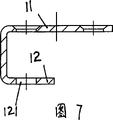
Fig. 6 is the stereogram of keeper push pedal embodiment of the present utility model;
Fig. 7 is the sectional view of Fig. 6.
[specific embodiment]
The utility model is a kind of Automatic door bolt, it includes keeper push pedal 1 and the bolt seat 2 that is installed in respectively on the two fan doors, in the chute 21 of this bolt seat 2, sliding door bolt assembly 3 is housed, the pushing mechanism 4 that can this promotion sliding door bolt assembly 3 slides in this bolt seat 2 is housed in the bottom of this sliding door bolt assembly 3, this pushing mechanism 4 includes vertical catch bar 41 and horizontal pushing block 42, and this horizontal pushing block 42 is fixed on this bolt seat 2 by bearing pin 5 and can rotates around this bearing pin 5; Stretch out from bolt seat 2 on one side of this horizontal pushing block 42, another side is provided with connecting rod 421, the other end of this connecting rod 421 flexibly connects with vertical catch bar 41, is provided with the grab 411 that can promote and draw this sliding door bolt assembly 3 at the other end of this vertical catch bar 41.At closing time, wherein the keeper push pedal 1 on the Yishanmen acts on the also rotation of use on this horizontal pushing block 42, laterally pushing block 42 makes vertical catch bar 41 promote 3 slips of sliding door bolt assembly by the connecting rod on it 421, when the top of sliding door bolt assembly 3 is inserted in the doorframe, finish the process of closing the door.Promote horizontal pushing block 42 expose the bolt seat reset open the door in, grab by vertical catch bar can spur the sliding door bolt assembly and fall down and open the door, the latch that the sliding door bolt assembly can not take place is stuck in the doorframe and the phenomenon that can't fall down, so it is of the present utility model rational in infrastructure, safe and reliable.
Described sliding door bolt assembly 3 includes latch 31, slide block 32, back-moving spring 33 and spring block 34, and wherein these latch 31 1 ends are connected with slide block 32 with spring block 34 successively, and the other end exposes from the sliding eye 22 of bolt seat 2; After this back-moving spring 33 was sleeved on this latch 31, the one end kept off on this spring block 34, and the other end keeps off in chute 21 inwalls of this bolt seat 2; Grab 411 on described vertical catch bar 41 can just be hooked in the hook groove 321 of this slide block 32.Described latch 31 includes jackshaft 311 and is socketed in the bolt cover 312 of these jackshaft 311 1 ends, and the other end of this jackshaft 311 is connected with slide block 32 with spring block 34 successively; This bolt cover 312 exposes a part from the sliding eye 22 of bolt seat 2 become the reeve end, is provided with arc angling 3121 on this reeve end; On this jackshaft 311, be with stage clip 35.The arc angling 3121 that bolt overlaps 312 insertion ends exposes the back playing the effect that guiding is inserted doorframe at closing time from keeper sliding eye 22, like this at closing time, can successfully be inserted in the doorframe, make close the door more smooth and easy.
In the embodiment shown in Fig. 6,7, described keeper push pedal 1 is " [" type, " side of [" type keeper push pedal 1 is to be used to promote the action plate 11 that this horizontal pushing block 42 rotates for this, opposite side is the fixed head 12 that is installed on other Yishanmen, tightens from the screw hole 121 of fixed head 12 with screw when mounted to get final product." [" type keeper push pedal 1 be subjected to force intensity very big, can stand the bigger power that 42 effects are come from horizontal pushing block, thereby improve application life of the present utility model.
Claims (4)
1, a kind of Automatic door bolt, it includes keeper push pedal (1) and the bolt seat (2) that is installed in respectively on the two fan doors, in the chute (21) of this bolt seat (2), sliding door bolt assembly (3) is housed, the pushing mechanism (4) that can this promotion sliding door bolt assembly (3) slides in this bolt seat (2) is housed in the bottom of this sliding door bolt assembly (3), this pushing mechanism (4) includes vertical catch bar (41) and horizontal pushing block (42), and this horizontal pushing block (42) is fixed on this bolt seat (2) by bearing pin (5) and goes up and can rotate around this bearing pin (5); Stretch out from bolt seat (2) on one side of this horizontal pushing block (42), another side is provided with connecting rod (421), the other end of this connecting rod (421) and vertically catch bar (41) flexible connection, it is characterized in that: the other end at this vertical catch bar (41) is provided with the grab (411) that can promote and draw this sliding door bolt assembly (3).
2, a kind of Automatic door bolt according to claim 1, it is characterized in that: described sliding door bolt assembly (3) includes latch (31), slide block (32), back-moving spring (33) and spring block (34), wherein these latch (31) one ends are connected with slide block (32) with spring block (34) successively, and the other end exposes from the sliding eye (22) of bolt seat (2); After this back-moving spring (33) was sleeved on this latch (31), the one end kept off on this spring block (34), and the other end keeps off in chute (21) inwall of this bolt seat (2); Grab (411) on described vertical catch bar (41) can just be hooked in the hook groove (321) of this slide block (32).
3, a kind of Automatic door bolt according to claim 2, it is characterized in that: described latch (31) includes jackshaft (311) and is socketed in the bolt cover (312) of these jackshaft (311) one ends, and the other end of this jackshaft (311) is connected with slide block (32) with spring block (34) successively; On the reeve end of this bolt cover (312), be provided with arc angling (3121); On this jackshaft (311), be with stage clip (35).
4, according to claim 1,2 or 3 described a kind of Automatic door bolts, it is characterized in that: described keeper push pedal (1) is " [" type, " side of [" type keeper push pedal (1) is to be used for promoting the action plate (11) that this horizontal pushing block (42) rotates, and opposite side is the fixed head (12) that is installed on other Yishanmen for this.
Priority Applications (2)
| Application Number | Priority Date | Filing Date | Title |
|---|---|---|---|
| CN 200620147571 CN200964744Y (en) | 2006-10-26 | 2006-10-26 | Automatic door bolt |
| MYPI20071190A MY178095A (en) | 2006-10-26 | 2007-07-23 | Automatic flush bolt |
Applications Claiming Priority (1)
| Application Number | Priority Date | Filing Date | Title |
|---|---|---|---|
| CN 200620147571 CN200964744Y (en) | 2006-10-26 | 2006-10-26 | Automatic door bolt |
Publications (1)
| Publication Number | Publication Date |
|---|---|
| CN200964744Y true CN200964744Y (en) | 2007-10-24 |
Family
ID=38868757
Family Applications (1)
| Application Number | Title | Priority Date | Filing Date |
|---|---|---|---|
| CN 200620147571 Expired - Fee Related CN200964744Y (en) | 2006-10-26 | 2006-10-26 | Automatic door bolt |
Country Status (2)
| Country | Link |
|---|---|
| CN (1) | CN200964744Y (en) |
| MY (1) | MY178095A (en) |
Cited By (1)
| Publication number | Priority date | Publication date | Assignee | Title |
|---|---|---|---|---|
| CN103255966A (en) * | 2013-05-14 | 2013-08-21 | 宁波埃迪五金工贸有限公司 | Toggle switch |
-
2006
- 2006-10-26 CN CN 200620147571 patent/CN200964744Y/en not_active Expired - Fee Related
-
2007
- 2007-07-23 MY MYPI20071190A patent/MY178095A/en unknown
Cited By (2)
| Publication number | Priority date | Publication date | Assignee | Title |
|---|---|---|---|---|
| CN103255966A (en) * | 2013-05-14 | 2013-08-21 | 宁波埃迪五金工贸有限公司 | Toggle switch |
| CN103255966B (en) * | 2013-05-14 | 2015-06-10 | 宁波埃迪五金工贸有限公司 | Toggle switch |
Also Published As
| Publication number | Publication date |
|---|---|
| MY178095A (en) | 2020-10-02 |
Similar Documents
| Publication | Publication Date | Title |
|---|---|---|
| CN200971725Y (en) | Self-lock electric control anti-theft door | |
| CN200964744Y (en) | Automatic door bolt | |
| CN200946408Y (en) | Panel lock | |
| CN2387219Y (en) | Auto-extending locking mechanism for spring bolt | |
| CN2873964Y (en) | Electromagnetic lock | |
| CN2716469Y (en) | Safety emergency door with a concealed push rod lock | |
| CN2736495Y (en) | Three-way linkage latch lock for anti-knock door | |
| CN2583298Y (en) | Safety lock for rolling-up door | |
| CN2685480Y (en) | Pulling or pushing lock | |
| CN2903292Y (en) | Auto locking mechanism of aluminium alloy window | |
| CN2898403Y (en) | Automatic locking mechanism | |
| CN2890264Y (en) | Single-bolt mortise door lock | |
| CN2315256Y (en) | Two-way open-and-close door device | |
| CN2682162Y (en) | Push-pull lock | |
| CN2438300Y (en) | Clasp type module locking mechanism | |
| CN201262005Y (en) | Mechanical locking type automatic door opening/closing device | |
| CN201074317Y (en) | Channel gate | |
| CN2634680Y (en) | Plug-in and pull-out device convenient for plug-in and pull-out circuit board | |
| CN2818678Y (en) | Lock tongue device | |
| CN2727337Y (en) | Automatic lock for door and window | |
| CN2830623Y (en) | Locking gear of shutter of rolling door | |
| CN2637999Y (en) | Pedal door opener for refrigerator | |
| CN2890257Y (en) | Lever type electrically-controlled lock | |
| CN2888026Y (en) | Automatic locking device of sliding door and window | |
| CN2702003Y (en) | Interlocking device for prizing-proof door lock |
Legal Events
| Date | Code | Title | Description |
|---|---|---|---|
| C14 | Grant of patent or utility model | ||
| GR01 | Patent grant | ||
| C17 | Cessation of patent right | ||
| CF01 | Termination of patent right due to non-payment of annual fee |
Granted publication date: 20071024 Termination date: 20091126 |