CN200950452Y - Battery breaking explosion proof valve and its explosion proof battery - Google Patents
Battery breaking explosion proof valve and its explosion proof battery Download PDFInfo
- Publication number
- CN200950452Y CN200950452Y CNU2006200178626U CN200620017862U CN200950452Y CN 200950452 Y CN200950452 Y CN 200950452Y CN U2006200178626 U CNU2006200178626 U CN U2006200178626U CN 200620017862 U CN200620017862 U CN 200620017862U CN 200950452 Y CN200950452 Y CN 200950452Y
- Authority
- CN
- China
- Prior art keywords
- explosion
- battery
- proof valve
- plate
- rigidly connected
- Prior art date
- Legal status (The legal status is an assumption and is not a legal conclusion. Google has not performed a legal analysis and makes no representation as to the accuracy of the status listed.)
- Expired - Lifetime
Links
Images


Classifications
-
- Y—GENERAL TAGGING OF NEW TECHNOLOGICAL DEVELOPMENTS; GENERAL TAGGING OF CROSS-SECTIONAL TECHNOLOGIES SPANNING OVER SEVERAL SECTIONS OF THE IPC; TECHNICAL SUBJECTS COVERED BY FORMER USPC CROSS-REFERENCE ART COLLECTIONS [XRACs] AND DIGESTS
- Y02—TECHNOLOGIES OR APPLICATIONS FOR MITIGATION OR ADAPTATION AGAINST CLIMATE CHANGE
- Y02E—REDUCTION OF GREENHOUSE GAS [GHG] EMISSIONS, RELATED TO ENERGY GENERATION, TRANSMISSION OR DISTRIBUTION
- Y02E60/00—Enabling technologies; Technologies with a potential or indirect contribution to GHG emissions mitigation
- Y02E60/10—Energy storage using batteries
-
- Y—GENERAL TAGGING OF NEW TECHNOLOGICAL DEVELOPMENTS; GENERAL TAGGING OF CROSS-SECTIONAL TECHNOLOGIES SPANNING OVER SEVERAL SECTIONS OF THE IPC; TECHNICAL SUBJECTS COVERED BY FORMER USPC CROSS-REFERENCE ART COLLECTIONS [XRACs] AND DIGESTS
- Y02—TECHNOLOGIES OR APPLICATIONS FOR MITIGATION OR ADAPTATION AGAINST CLIMATE CHANGE
- Y02P—CLIMATE CHANGE MITIGATION TECHNOLOGIES IN THE PRODUCTION OR PROCESSING OF GOODS
- Y02P70/00—Climate change mitigation technologies in the production process for final industrial or consumer products
- Y02P70/50—Manufacturing or production processes characterised by the final manufactured product
Abstract
The utility model provides an open circuit anti-exploding valve for a battery and an anti-exploding battery, including an anti-exploding valve slice, a rigid connection board having air holes and a plastic retaining ring. The anti-exploding valve slice is welded on the battery cover in an airtight way, the plastic retaining ring is fixed between the anti-exploding valve slice having an anti-exploding imprint and the rigid connection board, the plastic retaining ring separates the rigid connection board and the cover, the trace line of the anti-exploding imprint is same with and corresponds to the circular curve of the plastic retaining ring, the lower surface of the anti-exploding valve slice and the upper surface of the rigid connection board are connected by spot welding, and the rigid connection board also electrically connects with the positive electrode of the battery. The battery open circuit anti-exploding valve and the anti-exploding battery of the utility provide pressure relief for the buttery but also cut off the charging circuit inside the battery, stop charging to prevent the battery explosion when the battery is overcharging, occurs short-circuit inside or the internal pressure increases.
Description
Technical field
The utility model relates to secondary chemical sources of electric energy, and more particularly, the utility model relates to a kind of explosion-proof secondary cell.
Background technology
Modern society steps into the electronization epoch, and the dynamo-electric goods in the modern society, the kind of electronic equipment get more and more, quantity is more and more huger, wherein, is convenient for carrying and moves the chemical power source-battery that uses and be used widely.Battery commonly used comprises secondary cell that kind is various day by day such as Ni-MH battery, lithium ion battery, lithium battery, nickel-cadmium cell etc.
Secondary cells such as lithium ion cause internal short-circuit easily under the condition of overcharging, produce a large amount of heats even catch fire, and electrolyte moment is decomposed produce a large amount of gases, and when air pressure inside surpassed the pressure limit that housing bears, battery was promptly blasted.Therefore, safety anti-explosive is important performance index of secondary cell.Lithium battery adopts the aluminum or aluminum alloy material to make shell usually, for explosion-proof, the explosion-proof main employing housing of aluminum-shell battery is beaten explosion-proof India side formula both at home and abroad at present, and its technology is simple and easy relatively, cost is low, add trouble can for the battery manufacture process, so obtained using widely at home and abroad.
Though the mode of the explosion-proof seal of compacting has obtained using widely on the secondary cell housing, but in practice, traditional explosion-proof seal precision of detonating is not high, and because the battery anti-explosion valve is opened the back battery still can charge, also may be on fire, still there is the danger that causes security incident.
Summary of the invention
Above-mentioned shortcoming at prior art, the purpose of this utility model is that a kind of battery open circuit explosion-proof valve and anti-explosion battery thereof will be provided, it has following advantage: can be when over-charging of battery, internal short-circuit, inner pressure of battery rising, not only provide battery to rush down pressure, can also cut off the charging circuit in the battery, stop battery charge, thereby prevent the generation of battery explosion effectively.
For this reason, one of technical solution of the present utility model is a kind of battery explosion-proof valve that opens circuit, it comprises explosion-proof valve block, the be rigidly connected plate and the plastics back-up ring of band air-vent, described explosion-proof valve block is welded on the cover plate of battery hermetically, described plastics back-up ring is fixed in this explosion-proof valve block and is rigidly connected between the plate, be formed with explosion-proof impression on the described explosion-proof valve block, and described plastics back-up ring is separated described plate and the described cover plate of being rigidly connected, the trace line of described explosion-proof impression is identical and corresponding with the loop curve of described plastics back-up ring, have spot welding between the following and plate that is rigidly connected of described explosion-proof valve block top and connect, and the described plate that is rigidly connected the then anode ear of battery that also is electrically connected.
The utility model battery explosion-proof valve that opens circuit with aluminium cover plate and the explosion-proof valve block outer end as the anode conductor, and is electrically connected at the explosion-proof valve block of conduction and the spot welding that employing can be broken between plate that is rigidly connected of conduction.Because explosion-proof valve block has elastic deformability and comparatively weak, when charging causes inner pressure of battery excessively to raise, explosion-proof valve block is upwards made strain, thereby spot welding place is electrically connected to break breaks, make the charging circuit that is rigidly connected between plate and anode ear of cover plate and explosion-proof valve block and inside interrupt, cause battery charge to stop; If, battery charge stops still can not making inner pressure of battery to reply and is reduced to normally that the explosion-proof impression place that forms on the then explosion-proof valve block will ftracture, and battery be carried out secondary rush down pressure, thereby the safety that has fully guaranteed battery is rushed down pressure, has significantly improved the fail safe of battery.And the explosion-proof valve block that the utility model battery opens circuit in the explosion-proof valve directly realizes between plate being electrically connected with being rigidly connected of conduction, member is simple, it is reliable to connect, rush down the pressure influencing factor few, detonate that it is accurate, cheap for manufacturing cost to move.
The utility model explosion-proof valve concrete structure improves and also comprises:
The normal condition of described explosion-proof valve block is following concavity.
Described explosion-proof valve block and described being rigidly connected have 2 laser solder joints between plate.
Described plastics back-up ring frictional fit is in the perforate of described cover plate, and the described plate frictional fit that is rigidly connected is in the circle ring of described plastics back-up ring.
For when internal over pressure takes place, guarantee that fully explosion-proof valve block epirelief deformation energy cuts off the charge inside circuit, assurance is rigidly connected the mechanical rigid of plate greater than explosion-proof valve block, central authorities below the described plate that is rigidly connected have blind hole, radian has 2-4 pore equably around the blind hole, described explosion-proof valve block be welded on this blind hole position above.
Described anode ear is connected the following blind hole place of the described plate that is rigidly connected.
Correspondingly, another technical solution of the present utility model is a kind of anti-explosion battery, it comprises housing, cover plate, explosion-proof valve, positive pole and negative pole, described positive pole comprises cover plate, described explosion-proof valve comprises explosion-proof valve block, the be rigidly connected plate and the plastics back-up ring of band air-vent, described explosion-proof valve block is welded on the cover plate of battery hermetically, described plastics back-up ring is fixed in this explosion-proof valve block and is rigidly connected between the plate, be formed with explosion-proof impression on the described explosion-proof valve block, and described plastics back-up ring is separated described plate and the described cover plate of being rigidly connected, the trace line of described explosion-proof impression is identical and corresponding with the loop curve of described plastics back-up ring, have spot welding between the following and plate that is rigidly connected of described explosion-proof valve block top and connect, and the described plate that is rigidly connected the then anode ear of battery that also is electrically connected.
Owing to adopted the explosion-proof valve that opens circuit of the present utility model, anti-explosion battery of the present utility model can fully guarantee to rush down safely the fail safe of pressure and battery.
The concrete structure of the utility model anti-explosion battery improves and also comprises:
Have machinery between described housing and cover plate and be electrically connected.
Described anti-explosion battery is the rectangular aluminum housing battery.
Below in conjunction with the drawings and specific embodiments the utility model is described further.
Description of drawings
Fig. 1 is the elevational schematic view of the utility model embodiment 1 battery cover board and assembling thereof.
Fig. 2 be among Fig. 1 the A-A cross-sectional schematic and with the connection diagram of inside battery.
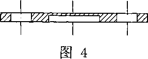
Fig. 3,4 is respectively looking up and B-B revolved section schematic diagram of the plate that is rigidly connected among Fig. 1.
Fig. 5 is that cross-sectional schematic is amplified in the part of Fig. 1 cover plate.
Fig. 6 is that cross-sectional schematic is amplified in the part of plastics back-up ring among Fig. 1.
Fig. 7 is the open circuit structural profile schematic diagram of explosion-proof valve embodiment 2 of the utility model battery.
Fig. 8 is that cross-sectional schematic is amplified in the part of Fig. 7 cover plate.
Fig. 9 is that cross-sectional schematic is amplified in the part of plastics back-up ring among Fig. 7.
Figure 10 is the open circuit local amplification profile schematic diagram of explosion-proof valve embodiment 1 of the utility model battery.
The schematic diagram that the explosion-proof valve that opens circuit among Fig. 1 when Figure 11 transfinites for inner pressure of battery distortion is opened circuit.
The schematic diagram of pressure is rushed down in the explosion-proof valve that opens circuit among Fig. 1 when Figure 12 continues to transfinite for inner pressure of battery distortion.
Embodiment
As Fig. 1-6,10, be depicted as the open circuit schematic diagram of each primary structure of explosion-proof valve and anti-explosion battery embodiment 1 of the utility model battery.The present embodiment anti-explosion battery comprises housing (not shown), cover plate 10, battery open circuit explosion-proof valve 20, electrode roll core 50, anodal 30 and negative pole 40, and described housing has machinery with 10 of cover plates and is electrically connected.Described anodal 30 comprise cover plate 10, and described anti-explosion battery is the rectangular aluminum housing battery.
Described explosion-proof valve 20 comprises explosion-proof valve block 21, the be rigidly connected plate 24 and the plastics back-up ring 22 of band air-vent, described explosion-proof valve block 21 is welded on the cover plate 10 of battery hermetically, described plastics back-up ring 22 is fixed in this explosion-proof valve block 21 and is rigidly connected between the plate 24, be formed with explosion-proof impression 25 on the described explosion-proof valve block 21, and described plastics back-up ring 22 is separated the described plate 24 that is rigidly connected with described cover plate 10, the trace line of described explosion-proof impression 25 is identical and corresponding with the loop curve of described plastics back-up ring 22, connect the described plate 24 that is rigidly connected the then anode ear 31 of battery that also is electrically connected between the following and plate 24 that is rigidly connected of described explosion-proof valve block 21 top by 2 laser solder joints 26.
The negative electrode lug 41 of drawing from electrode roll core 50 is connected on the negative terminal 42 by conducting strip 421, and negative terminal 42 is fixed in the single-order tapered-body pole hole 11 of cover plate 10 by insulating washer 43.Described anode ear 31 is connected following blind hole 240 places of the described plate 24 that is rigidly connected.
Described plastics back-up ring 22 frictional fit are in two ladder perforates 12 of described cover plate 10, and described plate 24 frictional fit that are rigidly connected are in the circle ring of described plastics back-up ring 22.
Central authorities below the described plate 24 of being rigidly connected have blind hole 240, and radian has 3 pores 241 equably around the blind hole 240, described explosion-proof valve block 21 be welded on these blind hole 240 positions above.
As Fig. 7--9, be depicted as the open circuit schematic diagram of each primary structure of explosion-proof valve embodiment 2 of the utility model battery.This embodiment 2 is except the sectional structure of the single-order ladder perforate 12 of holding plastics back-up ring 22 of cover plate 10 and plastics back-up ring 22 is not quite similar, and other each primary structure homogeneous phases are similar to embodiment 1.
As Figure 11, when charging causes inner pressure of battery excessively to raise, because explosion-proof valve block 21 has elastic deformability and comparatively weak, the strain that explosion-proof valve block 21 works raise up, thereby the electrical connection of solder joint 26 broken break, make the charging circuit of cover plate 10 and explosion-proof valve block 21 and inner be rigidly connected 31 of plate 24 and anode ears interrupt, cause battery charge to stop;
As Figure 12, if battery charge stops still can not making inner pressure of battery to reply and is reduced to normally that explosion-proof impression 25 places that form on the then explosion-proof valve block 21 will ftracture, and battery be carried out secondary rush down pressure, thereby the safety that has fully guaranteed battery is rushed down pressure, significantly improves the fail safe of battery.
Claims (9)
1, a kind of battery explosion-proof valve that opens circuit, it comprises explosion-proof valve block, the be rigidly connected plate and the plastics back-up ring of band air-vent, described explosion-proof valve block is welded on the cover plate of battery hermetically, described plastics back-up ring is fixed in this explosion-proof valve block and is rigidly connected between the plate, be formed with explosion-proof impression on the described explosion-proof valve block, it is characterized in that: described plastics back-up ring is separated described plate and the described cover plate of being rigidly connected, the trace line of described explosion-proof impression is identical and corresponding with the loop curve of described plastics back-up ring, have spot welding between the following and plate that is rigidly connected of described explosion-proof valve block top and connect, and the described plate that is rigidly connected the then anode ear of battery that also is electrically connected.
2, the battery explosion-proof valve that opens circuit according to claim 1 is characterized in that: the normal condition of described explosion-proof valve block is concavity down.
3, the battery explosion-proof valve that opens circuit as claimed in claim 1 or 2, it is characterized in that: described explosion-proof valve block and described being rigidly connected have 2 laser solder joints between plate.
4, the battery explosion-proof valve that opens circuit as claimed in claim 1 or 2, it is characterized in that: described plastics back-up ring frictional fit is in the perforate of described cover plate, and the described plate frictional fit that is rigidly connected is in the circle ring of described plastics back-up ring.
5, the battery explosion-proof valve that opens circuit as claimed in claim 1 or 2, it is characterized in that: the central authorities below the described plate that is rigidly connected have blind hole, radian has 2-4 pore equably around the blind hole, described explosion-proof valve block be welded on this blind hole position above.
6, as the explosion-proof valve that opens circuit of battery as described in the claim 5, it is characterized in that: described anode ear is connected the following blind hole place of the described plate that is rigidly connected.
7, a kind of anti-explosion battery, it comprises housing, cover plate, explosion-proof valve, positive pole and negative pole, described positive pole comprises cover plate, described explosion-proof valve comprises explosion-proof valve block, the be rigidly connected plate and the plastics back-up ring of band air-vent, described explosion-proof valve block is welded on the cover plate of battery hermetically, described plastics back-up ring is fixed in this explosion-proof valve block and is rigidly connected between the plate, be formed with explosion-proof impression on the described explosion-proof valve block, it is characterized in that: described plastics back-up ring is separated described plate and the described cover plate of being rigidly connected, the trace line of described explosion-proof impression is identical and corresponding with the loop curve of described plastics back-up ring, have spot welding between the following and plate that is rigidly connected of described explosion-proof valve block top and connect, and the described plate that is rigidly connected the then anode ear of battery that also is electrically connected.
8, as anti-explosion battery as described in the claim 7, it is characterized in that: have machinery between described housing and cover plate and be electrically connected.
9, as anti-explosion battery as described in the claim 7, it is characterized in that: described anti-explosion battery is the rectangular aluminum housing battery.
Priority Applications (1)
| Application Number | Priority Date | Filing Date | Title |
|---|---|---|---|
| CNU2006200178626U CN200950452Y (en) | 2006-08-23 | 2006-08-23 | Battery breaking explosion proof valve and its explosion proof battery |
Applications Claiming Priority (1)
| Application Number | Priority Date | Filing Date | Title |
|---|---|---|---|
| CNU2006200178626U CN200950452Y (en) | 2006-08-23 | 2006-08-23 | Battery breaking explosion proof valve and its explosion proof battery |
Publications (1)
| Publication Number | Publication Date |
|---|---|
| CN200950452Y true CN200950452Y (en) | 2007-09-19 |
Family
ID=38892993
Family Applications (1)
| Application Number | Title | Priority Date | Filing Date |
|---|---|---|---|
| CNU2006200178626U Expired - Lifetime CN200950452Y (en) | 2006-08-23 | 2006-08-23 | Battery breaking explosion proof valve and its explosion proof battery |
Country Status (1)
| Country | Link |
|---|---|
| CN (1) | CN200950452Y (en) |
Cited By (4)
| Publication number | Priority date | Publication date | Assignee | Title |
|---|---|---|---|---|
| CN102779961A (en) * | 2012-08-20 | 2012-11-14 | 常州市武进中瑞电子有限公司 | Aluminium soldering integrating type-cylindrical aluminum shell battery anti-explosion combined cover plate |
| CN104659315A (en) * | 2013-11-21 | 2015-05-27 | 现代摩比斯株式会社 | Apparatus for preventing overcharge of battery |
| CN102136552B (en) * | 2010-01-27 | 2015-11-25 | 深圳市比克电池有限公司 | The manufacture method of battery protecting apparatus, battery and battery protecting apparatus |
| CN110518296A (en) * | 2019-08-30 | 2019-11-29 | 广州华其电子有限公司 | A kind of anti-overcharge nickel-metal hydride battery of high-capacity intelligent protection type |
-
2006
- 2006-08-23 CN CNU2006200178626U patent/CN200950452Y/en not_active Expired - Lifetime
Cited By (5)
| Publication number | Priority date | Publication date | Assignee | Title |
|---|---|---|---|---|
| CN102136552B (en) * | 2010-01-27 | 2015-11-25 | 深圳市比克电池有限公司 | The manufacture method of battery protecting apparatus, battery and battery protecting apparatus |
| CN102779961A (en) * | 2012-08-20 | 2012-11-14 | 常州市武进中瑞电子有限公司 | Aluminium soldering integrating type-cylindrical aluminum shell battery anti-explosion combined cover plate |
| CN104659315A (en) * | 2013-11-21 | 2015-05-27 | 现代摩比斯株式会社 | Apparatus for preventing overcharge of battery |
| CN104659315B (en) * | 2013-11-21 | 2017-11-14 | 现代摩比斯株式会社 | The anti-locking apparatus of over-charging of battery |
| CN110518296A (en) * | 2019-08-30 | 2019-11-29 | 广州华其电子有限公司 | A kind of anti-overcharge nickel-metal hydride battery of high-capacity intelligent protection type |
Similar Documents
| Publication | Publication Date | Title |
|---|---|---|
| CN2631052Y (en) | Lithium ion cell | |
| US7572544B2 (en) | Sealed rechargeable battery | |
| US20080213657A1 (en) | High Capacity Lithium Ion Secondary Battery with Metal Case | |
| KR101075284B1 (en) | Secondary Battery | |
| US20060099500A1 (en) | Secondary battery | |
| JP5245536B2 (en) | battery | |
| EP1973182A1 (en) | Secondary batery | |
| EP2472641A1 (en) | Nickel-zinc battery and manufacturing method thereof | |
| CN112531295A (en) | Lithium ion battery structure and tab electric connection method | |
| WO2020133555A1 (en) | Rechargeable button-type soft-pack lithium-ion battery and processing method therefor | |
| JP5173095B2 (en) | Sealed battery | |
| CN104505482A (en) | New lithium ion battery with protection function and preparation process thereof | |
| CN200950452Y (en) | Battery breaking explosion proof valve and its explosion proof battery | |
| WO2022237030A1 (en) | Traction battery cover and traction battery | |
| CN201673952U (en) | Dual safety explosion-proof device of power lithium battery | |
| JPH10312783A (en) | Secondary battery and its manufacture | |
| US20240097286A1 (en) | Current Collector Component and Secondary Battery | |
| KR20190084874A (en) | Nonaqueous electrolyte secondary battery | |
| CN108123179B (en) | Power battery of electric automobile | |
| CN210778688U (en) | Soft packet of lithium cell packaging structure | |
| JP2003051292A (en) | Sealed battery and sealing plate thereof | |
| CN215451575U (en) | Rechargeable lithium battery | |
| CN210984769U (en) | Power battery and car | |
| CN113517501A (en) | Battery and power consumption device containing same | |
| KR20080049545A (en) | Separator for lithium rechargeable battery and lithium rechargeable battery using the same |
Legal Events
| Date | Code | Title | Description |
|---|---|---|---|
| C14 | Grant of patent or utility model | ||
| GR01 | Patent grant | ||
| C56 | Change in the name or address of the patentee | ||
| CP02 | Change in the address of a patent holder |
Address after: Two road 518118 Guangdong city of Shenzhen province Pingshan Pingshan biling community bunker No. 38 Patentee after: HYB Battery Co., Ltd. Address before: 518111 Fumin Industrial Zone, Pinghu Town, Longgang District, Guangdong, Shenzhen, 13-16 Patentee before: HYB Battery Co., Ltd. |
|
| CX01 | Expiry of patent term |
Granted publication date: 20070919 |
|
| EXPY | Termination of patent right or utility model |