CN1984003A - Distributed communication equipment architectures and techniques - Google Patents
Distributed communication equipment architectures and techniques Download PDFInfo
- Publication number
- CN1984003A CN1984003A CNA2006100640323A CN200610064032A CN1984003A CN 1984003 A CN1984003 A CN 1984003A CN A2006100640323 A CNA2006100640323 A CN A2006100640323A CN 200610064032 A CN200610064032 A CN 200610064032A CN 1984003 A CN1984003 A CN 1984003A
- Authority
- CN
- China
- Prior art keywords
- communication
- communication link
- interface
- equipment
- module
- Prior art date
- Legal status (The legal status is an assumption and is not a legal conclusion. Google has not performed a legal analysis and makes no representation as to the accuracy of the status listed.)
- Granted
Links
Images


Classifications
-
- H—ELECTRICITY
- H04—ELECTRIC COMMUNICATION TECHNIQUE
- H04Q—SELECTING
- H04Q11/00—Selecting arrangements for multiplex systems
- H04Q11/04—Selecting arrangements for multiplex systems for time-division multiplexing
-
- H—ELECTRICITY
- H04—ELECTRIC COMMUNICATION TECHNIQUE
- H04Q—SELECTING
- H04Q2213/00—Indexing scheme relating to selecting arrangements in general and for multiplex systems
- H04Q2213/13003—Constructional details of switching devices
-
- H—ELECTRICITY
- H04—ELECTRIC COMMUNICATION TECHNIQUE
- H04Q—SELECTING
- H04Q2213/00—Indexing scheme relating to selecting arrangements in general and for multiplex systems
- H04Q2213/1301—Optical transmission, optical switches
-
- H—ELECTRICITY
- H04—ELECTRIC COMMUNICATION TECHNIQUE
- H04Q—SELECTING
- H04Q2213/00—Indexing scheme relating to selecting arrangements in general and for multiplex systems
- H04Q2213/13039—Asymmetrical two-way transmission, e.g. ADSL, HDSL
-
- H—ELECTRICITY
- H04—ELECTRIC COMMUNICATION TECHNIQUE
- H04Q—SELECTING
- H04Q2213/00—Indexing scheme relating to selecting arrangements in general and for multiplex systems
- H04Q2213/13092—Scanning of subscriber lines, monitoring
-
- H—ELECTRICITY
- H04—ELECTRIC COMMUNICATION TECHNIQUE
- H04Q—SELECTING
- H04Q2213/00—Indexing scheme relating to selecting arrangements in general and for multiplex systems
- H04Q2213/13094—Range extender
-
- H—ELECTRICITY
- H04—ELECTRIC COMMUNICATION TECHNIQUE
- H04Q—SELECTING
- H04Q2213/00—Indexing scheme relating to selecting arrangements in general and for multiplex systems
- H04Q2213/13106—Microprocessor, CPU
-
- H—ELECTRICITY
- H04—ELECTRIC COMMUNICATION TECHNIQUE
- H04Q—SELECTING
- H04Q2213/00—Indexing scheme relating to selecting arrangements in general and for multiplex systems
- H04Q2213/13109—Initializing, personal profile
-
- H—ELECTRICITY
- H04—ELECTRIC COMMUNICATION TECHNIQUE
- H04Q—SELECTING
- H04Q2213/00—Indexing scheme relating to selecting arrangements in general and for multiplex systems
- H04Q2213/13166—Fault prevention
-
- H—ELECTRICITY
- H04—ELECTRIC COMMUNICATION TECHNIQUE
- H04Q—SELECTING
- H04Q2213/00—Indexing scheme relating to selecting arrangements in general and for multiplex systems
- H04Q2213/13178—Control signals
-
- H—ELECTRICITY
- H04—ELECTRIC COMMUNICATION TECHNIQUE
- H04Q—SELECTING
- H04Q2213/00—Indexing scheme relating to selecting arrangements in general and for multiplex systems
- H04Q2213/13191—Repeater
Abstract
The invention discloses distributed communication equipment architectures and techniques. A host system includes an expansion unit through which control information and communication traffic may be exchanged with an expansion system. The expansion system is thereby controllable by a controller at the host system, significantly simplifying the design and reducing the cost of the expansion system. The expansion unit for a host system may also provide one or more configurable communication link interfaces. Each configurable interface may be independently configured as a network-side interface for connection to upstream communication equipment or as an access-side expansion interface for connection to an expansion system, allowing provisioning of network and access interfaces at the host system as needed.
Description
The cross reference of related application
The sequence number that the application relates to common transfer is 11/264,451, title is the U.S. Patent application on November 1st, 2005 for " REMOTE CONTROLAND CONTROL REDUNDANCY FOR DISTRIBUTED COMMUNICATION EQUIPMENT (Long-distance Control of distributed communication equipment and control redundancy) ", the applying date.
Technical field
Relate generally to communication of the present invention specifically, relates to distributed communication equipment architectures and correlation technique.
Background technology
In the communication system of some types, for example be used to provide the system of Digital Subscriber Line business, communication service quality is along with the increase of the distance of access communications equipment and descend.A kind of possible method that alleviates this class problem is to arrange access device more near the user.But with regard to original equipment cost and sustainable management and maintenance cost, it is the cost costliness that this method is tended to.
Distributed systems architecture is represented a kind of more feasible alternative construction that is used for moving towards customer rs site access function.There are some distributed system solutions available now.
Some telecommunications equipment providers have been thrown in the DSL access product to market, and these products mainly are based on the scaled down version of the system of central office (CO).In these systems, in fact CO does not have subregion.More properly, distributed unit is the scaled down version of CO equipment.
According to these solutions, basic function is replicated rather than is distributed.Each distributed remote unit has kept most of cost, size and the power requirement of CO equipment.This has increased the cost of whole system.
One in the DSL system can be known as " loop expansion " for solution relatively.In this case, DSL circuit itself is retransmitted or carry via some other mediums, and is replicated at remote location.But this solution not only needs typical C O equipment, but also needs relay equipment, has increased whole cost.
Embodiments of the invention provide further improved distributed communication equipment architectures and correlation technique, have simpler and distributed component more cheaply.
Summary of the invention
Some embodiments of the present invention have solved in the effective and telescopic mode of cost the problem of DSL service delivery to a large number of users.A kind of telescopic distributed access node system architecture is provided, and this architecture can comprise the main system of the respective sets of one or more expansion modules (SEM) that are connected to satellite extension frame system and/or sealing, and it has the DSL interface to be connected to user's customer site equipment (CPE).For example, in one embodiment, the physical layout of extension frame system is identical with the physical layout of main system, makes it can easily be converted into other main systems, to satisfy the extension of network requirement.For example, need a kind of simple and service supplier that the effective migration plan of cost is expanded its access network for increasing along with customer group, this is an important advantage.
The communication link that distributed access node system is provided as network link or access link in, other embodiment of the present invention provide flexibility.This flexibility allows to come extended network to cover according to user's request, and this is even more important for the DSL business (" triple play " business of for example so-called internet, video and voice) that strengthens.Special-purpose and configurable interface, for example gigabit Ethernet (Gig-E) interface are provided at the main system place of distributed access node system.For example, for the quantity that reduces special-purpose physical connector (can plug (SFP) port as the small form factor on the electronic circuit card faceplate at main system place), configurable interface can be useful, and the saving in cost and space is provided thus.
According to an aspect of the present invention, provide a kind of device that comprises interface and expansion module.Described interface allows the controller intercommunication control information with communication equipment, and described controller can be configured to the communication module exchange of control information with the partial controllable system of described communication equipment.Described expansion module is operably connected to described interface, and is suitable for control information transmission between the may command communication module of described controller and expanding communication equipment.
Described interface can also allow and described expansion module switched communication business.In this case, described expansion module also is suitable for transmission of traffic between described communication equipment and described expanding communication equipment.
In certain embodiments, described communication equipment is by communication link and the communication service of uplink communication devices exchange, and described device also comprises the uplink communication LI(link interface), and it is used for allowing by other communication links and described uplink communication devices communicating.
Described device can also comprise configurable communication link interface.Described configurable communication link interface can be configured to allow by uplink communication link and uplink communication devices communicating, or by expanding communication link and described expanding communication devices communicating.
A plurality of communication link interface can be provided, comprise the interface of one or more following types: the uplink communication LI(link interface), it is used for allowing by uplink communication link and uplink communication devices communicating; The downlink communication LI(link interface), it is used for allowing by downlink communication link and described expanding communication devices communicating; And configurable communication link interface, described configurable communication link interface can be configured to allow by uplink communication link and described uplink communication devices communicating, or by downlink communication link and described expanding communication devices communicating.
Described device can for example be provided in the main system of distributed communication network element.Described distributed communication network element can also comprise the expanding system that comprises described expanding communication equipment, and the communication link between described main system and described expanding system.
Described main system and described expanding system can comprise the relevant device frame with universal architecture.Wherein said main system comprises first electronic circuit cards of the first kind that comprises described interface and described expansion module, and second electronic circuit cards that comprises second type of controller, be installed in the described expanding system equipment rack by corresponding electronic circuit card, can convert described expanding system to main system described first and second types.
Described expanding system can comprise: communication link interface, and it is operably connected to described communication link; And trunk module, it is operably connected to described communication link interface and is suitable for control information transmission between described main system and described controllable communication module.
According to another aspect of the present invention, provide the expansion equipment assembly in device, described device comprises communication link interface, and it is used for allowing to communicate by letter with telecommunication equipment by communication link.Described telecommunication equipment comprises controller, and described controller can be configured to the may command communication module exchange of control information with described telecommunication equipment.This device can also comprise trunk module, and it is operably connected to described communication link interface, and is suitable for control information transmission between described controller and the partial controllable system communication module related with described communication link interface.
Described trunk module also is suitable for transmission of traffic between described telecommunication equipment and described partial controllable system communication module.
Wherein said communication link comprises optical communication link, and at least one in described interface and the described trunk module comprises be used for the transducer changed between the light and the signal of telecommunication.
In certain embodiments, described communication link is a communication network side communication link, and described partial controllable system communication module is suitable for and access side communication link intercommunication communication service.Described access side communication link provides the access of described communication network.
Described expansion equipment can for example be embodied as the expansion module of sealing.
According to other aspects of the invention, provide a kind of method, having comprised: the communication equipment frame is provided, and described equipment rack has the slot that is used to hold electronic circuit cards; The electronic circuit cards of the first kind comprise controller is installed in first slot of described equipment rack, and described controller can be configured to and be installed in the partial controllable system communication module exchange of control information in other slots of described equipment rack; And the electronic circuit cards that second type with interface is installed in second slot of described equipment rack, described interface is used for allowing and described controller and expansion module intercommunication control information, described expansion module is operably connected to described interface, and is suitable for control information transmission between the may command communication module of described controller and expanding communication equipment.
Describedly provide operation to comprise the expanding communication equipment rack with the electronic circuit cards that is installed in the 3rd type in described first slot is provided.The electronic circuit cards of described the 3rd type has the communication link interface that permission is communicated by letter with telecommunication equipment by communication link.Described telecommunication equipment comprises: controller, and it can be configured to the may command communication module exchange of control information with described telecommunication equipment; And trunk module, it is operably connected to described interface, and is suitable for control information transmission between described controller and the partial controllable system communication module related with described communication link interface.In this case, described method can comprise the additional operations that removes the electronic circuit cards of described the 3rd type from described first slot.
Described telecommunication equipment can with the communication service of uplink communication devices exchange, and the one or more cards in the electronic circuit cards of the electronic circuit cards of the described first kind and described second type can be provided for allowing the communication link interface that communicates by communication link.Described method can comprise that then the described communication link interface with the one or more cards in the electronic circuit cards of the electronic circuit cards of the described first kind and described second type is operably connected to the operation of described uplink communication equipment.
Another aspect of this aspect provides a kind of device, and described device has: expansion module, and it is used in transmit communications signals between communication equipment and the uplink communication equipment and between described communication equipment and downlink communication equipment; And a plurality of communication link interface, it is operably connected to described expansion module.Described communication link interface comprises configurable communication link interface, and this interface can be configured to and allows to pass through uplink communication link and described uplink communication devices communicating or pass through downlink communication link and described downlink communication devices communicating.
Described communication link interface can also comprise one or more with lower interface: the dedicated uplink communication link interface, and it is used for allowing by other uplink communication links and described uplink communication devices communicating; And the private downlink communication link interface, it is used for allowing by other downlink communication links and described downlink communication devices communicating.
In one embodiment, described configurable communication link interface is operably connected to a pair of switch ports themselves of switch.Except this to switch ports themselves, described switch also has the corresponding switch ports themselves that is operably connected to described a plurality of communication link interface.Described switch is suitable for exchanges communication signals between upstream switch port and Downlink Switch port.The described switch ports themselves that is connected to described configurable communication link interface is to comprising upstream switch port and Downlink Switch port.
Described device can also comprise configurable selector, it is operably connected to described configurable interface and described switch ports themselves is right, and described selector can be configured to a switch ports themselves of described switch ports themselves centering is operably connected to described configurable interface.
After the description below having checked, other aspects and the feature of embodiments of the invention will become apparent those skilled in the art.
Description of drawings
Describe the example of embodiments of the invention in detail referring now to accompanying drawing, these accompanying drawings are:
Fig. 1 is the calcspar of communication system;
Fig. 2 is the calcspar of distributed architecture according to an embodiment of the invention;
The calcspar of the connection that Fig. 3 has been an illustration between switch and the communication link interface;
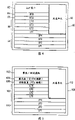
The calcspar of the physical layout of primary system component frame that Fig. 4 is an illustration;
The calcspar of the physical layout of Fig. 5 is illustration expanding system equipment rack;
Fig. 6 is the flow chart that expanding system is converted to the method for main system;
Fig. 7 is from the flow chart of main system to the method for expanding system control information transmission; And
Fig. 8 is from the flow chart of expanding system to the method for main system control information transmission.
Embodiment
Fig. 1 is the calcspar that wherein can realize the communication system 10 of embodiments of the invention.Communication system 10 comprises a plurality of CPE devices 12/14,13/15, network element 16,17, and communication network 18.Although in Fig. 1, only show 12/14,13/15 and two network element 16,17 of four CPE for fear of crowding, more CPE and network element can be connected to communication network 18.Therefore, should be appreciated that the system of Fig. 1 and the content of other accompanying drawings all only are intended to be used for the example purpose, and do not limit the invention to explicit in the accompanying drawings illustrating and particular instance embodiment described here by any way.
CPE 12/14,13/15 expression communication equipment, for example end user's communication equipment is configured to receive and/or send signal of communication.Be directly connected to network element 16,17 although be shown, it is evident that, CPE 12/14,13/15 can communicate by letter with network element 16,17 by other intermediate module (not shown).In one embodiment, the CPE connection is the local twisted pair loop that is used to set up the DSL communication link.
Switch and router are the examples by the type of the communication equipment of network element 16,17 expressions.For example, when the CPE connection was the DSL connection, network element 16,17 can be DSLAM, higher level service access multiplexer (ASAM), or intelligent subscriber access manager (ISAM). Network element 16,17 is provided to the access of communication network 18 for CPE 12/14,13/15, and therefore can realize in communication network 18.But for illustrative purposes, network element 16,17 is illustrated as separating with communication network 18 in Fig. 1.
Except network element 16,17, communication network 18 can also comprise other network elements that come the route signal of communication by communication network 18.
For those skilled in the art, many dissimilar end users, media and network communication equipment and operation thereof will be conspicuous.Usually, network element 16,17 transmit communications signals between communication network 18 and CPE 12/14,13/15.According to a specific example execution mode, network element 16,17 is communicated by letter with CPE 12/14,13/15 by the DSL communication link by other devices communicatings in Gig-E communication link and the communication network.But embodiments of the invention are not limited to communication equipment, transfer mechanism or the agreement of any particular type.Except that Ethernet and DSL communication link, architecture disclosed herein and technology can also be used with other networks and link.
As mentioned above, for example, may wish to arrange the communication network access device as far as possible near CPE, to improve the communication on the DSL communication link.According to embodiments of the invention, provide communication service to a large amount of CPE from distributed access device (for example, distributed Very High Speed DSL (VDSL) access node).This distributed apparatus can be provided with the form of central master device and expansion equipment, and described expansion equipment is connected to described main equipment, but is distributed in geographically in the short distance of communication service user.
Fig. 2 is the calcspar of distributed architecture according to an embodiment of the invention.The distributed apparatus system 20 of Fig. 2 comprises main equipment 22 and expansion equipment 24, and they operationally are connected to each other by one or more communication links 26.
Main equipment 22 comprises one or more communication link interface 34 that are operably connected to switch 36, and the controller 32 that also is operably connected to switch 36.Inside connection in the unit 30 and/or other the inner forms that connect in the equipment 22,24 can change with different execution modes.In one embodiment, provide communication link interface (a plurality of) 34, switch 36 and controller 32 in electronic circuit cards 30 (for example network termination (NT) card), in this case, inner connection can be the suprabasil trace of card or other conductors.Those skilled in the art will be familiar with providing the NT card of communication link interface, switch and controller and the various examples of other assemblies.
Expansion module 42 is operably connected to one or more communication link interface 44 that may be arranged in other electronic circuit cards 40.
Switch 36 also is operably connected to one or more communication modules 46, and described module for example can be line termination (LT) card.Each communication module 46 comprises signal of communication processor 47 and one or more transceiver 49.Transceiver 49 makes communication module 46 to communicate by letter with one or more CPE by the access communications link.
For fear of crowded, the interface of the connection between the assembly 30,40,46 is not shown individually in Fig. 2.But, should be appreciated that the interconnection (connecting as the inside of pointing out above) of these inter-modules can be taked any different form.For example, be provided as corresponding electronic circuit cards so that be installed under the situation in the slot of equipment rack at assembly 30,40,46, the interface element on the assembly can allow to carry out inter-component communication by the physical connector that provides in back-plate conductor and the card slot.Other execution modes of inter-module interface also are possible.Therefore, the interface that allows to communicate by letter between the assembly can comprise just conductor or other physical medium, be used to be connected to conductor or other interface elements of physical medium, and/or may have other possible elements of more " activation " function than the connection that is created to physical medium.
Expansion equipment 24 comprises control device 50 and one or more communication module 60.Control device 50 comprises one or more communication link interface 52, is operably connected to the trunk module 54 of each communication link interface 52, and controller 56.Trunk module 54 and controller 56 all are operably connected to the signal of communication processor 64 of each communication module 60.Each communication module 60 comprises one or more transceivers 62, communicates by letter with one or more CPE by inserting the side communication link with permission.
The various forms of the interface of having conceived the inside connection in control device 50 and each communication module 60 and having allowed to communicate by letter between these assemblies.For example, when assembly 50,60 was provided as Equipment Control card and one or more LT, the inner connection may be provided in trace or other conductors, and the inter-module connection can be by back-plate conductor or other connections that provides in expansion equipment 24.
The present invention is not limited to the assembly of any particular type shown in Fig. 2.For example, different telecommunications equipment providers can be realized these assemblies in a different manner.The example that describes below for the purpose of example, is not to be intended to limit the scope of the invention by any way just.
The uplink and downlink communication link, and communication link interface 34,44,52 can have identical or different type.In one embodiment, the communication link (a plurality of) of the uplink communication equipment to switch/router in the communication network core or the DSL CO, and to the communication link (a plurality of) the 26th of expansion equipment 24, Gig-E optical link, and communication link interface the 34,44, the 52nd, SFP port device.
Switch 36 (as the Local Area Network switch) exchanges communication signals between uplink communication link and downlink communication link.This function of exchange can be under the control of controller 32, although in other embodiments, switch 36 may not need to come the input of self-controller 32 to control the actual exchange function.Switch 36 can itself can be visited routing table or other information, to determine how to exchange from uplink communication link (a plurality of), the signal of communication that communication module (a plurality of) 46 and/or expansion equipment 24 receive.In this case, controller 32 can be used to create/manage the routing table of switch 36, but does not directly control the function of exchange of switch.
Controller 32 can be configured to controls communication module (a plurality of) 46 at least, and may control other elements of main equipment 22.Can by controller 32 carry out such as enable and/or these type of controlled function such as the control of disable communications module (a plurality of) 46, power supply, test, the supervision of reporting to the police in any function or repertoire.Further crowded in Fig. 2, the not explicit independent control connection that illustrates between controller 32 and the communication module (a plurality of) 46.But should be appreciated that controller 32 can be via independent control path and communication module (a plurality of) 46 intercommunication control informations.
In one embodiment, controller 32 uses the in-band signalling technology to control local communication module (a plurality of) 46, does not need the control connection of migrating like this between controller 32 and local communication module.As described in greater detail, controller 32 also uses in-band signalling to control one or more expanding communication modules 60 of expansion equipment 24.
The execution mode of controller 32 can comprise the hardware execution mode, the software implementation mode (wherein Control Software be stored in the memory (not shown) and by one or more treatment elements (as microprocessor, microcontroller, application-specific integrated circuit (ASIC) (ASIC), and/or field programmable gate array (FPGA)) carries out), firmware execution mode, or their certain combination.
Each communication module 46 can comprise hardware, software and/or firmware function element, and they are by signal of communication processor 47 and transceiver (a plurality of) 49 expressions and handle transmission communication signal between main equipment 22 and other communication equipments (for example CPE).Communication module (a plurality of) 46 can have communication module (a plurality of) the 60 essentially identical structures with expansion equipment 24.In one embodiment, main equipment 22 all uses identical LT card with expansion equipment 24, although the one or more LT cards in the expansion equipment can be disposed slightly differently, specifically, handle the control information of autonomous device controller 32, as described in more detail below.
Control device 50 makes master controller 32 can control one or more functions of expansion equipment 24.According to embodiments of the invention, the control of communication module (a plurality of) 60 finally is responsible for by controller 32.But, control device 50 can participate in controlling communication module (a plurality of) 60, and wherein its local control 56 can come actual execution control function according to the control information that slave controller 32 receives and/or will report to controller 32 such as the control information test result and the alarm condition.
From the assembly of communication link interface (a plurality of) 52 to communication module (a plurality of) 60 transmission signals of communication, this signal of communication can comprise communication service, control information, or the both comprises by control device 50 in trunk module 54 expressions.The function of trunk module 54 can include only relay function, maybe may comprise simple signal processing function, for example level conversion and/or light/electrical signal conversion.In certain embodiments, trunk module 54 is embodied as one or more conductors that signal path is provided simply between each communication link interface 52 and corresponding communication module 60.According to a specific example execution mode, each communication link interface 52 is SFP, it comprises signal converter, is used at the light signal that transmits on the link (a plurality of) 26 and is delivered to converts communications signal between the signal of telecommunication of communication module (a plurality of) 60 by trunk module 54.
When a plurality of communication link interface 52 was provided, trunk module 54 provides many paths to communication module (a plurality of) 60, and was as described in more detail below.In this case, preferably between each communication link interface 52 and corresponding communication module 60, has mapping one to one.
Should be pointed out that the different execution modes of having conceived expansion equipment 24.According to an embodiment, use essentially identical equipment rack but dissimilar electronic circuit cards to make up main equipment 22 and expansion equipment 24.But in other embodiments, expansion equipment 24 is implemented as the expansion module of the sealing that comprises control device 50 and single communication module 60.When communication network insert will be provided for expectation can phenomenal growth and can use single communication module 60 that the less relatively customers of service are provided the time, can use the module of sealing.As skilled in the art will appreciate, single LT card can support 24,28 or more physical port and access link.Should correspondingly explain this quoting expanding system and equipment.
As described in greater detail, master controller 32 is major control devices of distributed system 20, and is connected to uplink communication equipment, for example other communication network elements in CO or the communication network core.Main equipment 22 is the most complicated and the most expensive parts in the distributed system 20.
By adding special element 40 (for example electronic circuit cards), main equipment 22 can be connected to the additional uplink communication link and/or the expansion equipment of one or more installations.Expansion equipment 24 comprises the unit 50 (may be another electronic circuit cards) of another particular design, and it is connected to one or more descending expanding communication links from main equipment 22, and as shelf controller, although be under the final control of controller 32.
Be in operation, expansion module 42 is control information transmission between the controller 32 of main equipment 22 and expanding communication link (a plurality of) 26.This allows exchange of control information between master controller 32 and extending controller 56.Control information can comprise, for example, goes to the controller 56 of expansion equipment 24 so that the control information of controller 56 execution control functions maybe may be the information of collecting and being sent to controller 32 by controller 56, as the condition that monitors, alarm etc.According to one embodiment of present invention, the control information of going to expansion equipment controller 56 by be used to transmit the identical communication link of communication service (a plurality of) 26 and be sent to expansion equipment 24 from main equipment 22, described control information is also referred to as band inner control signaling.In the case, controller 32 can insert control information the signal of communication by switch 36 exchanges, control information is offered switch 36 so that exchange in the mode identical with communication service, perhaps control information is offered expansion module 42 or interface (a plurality of) 44 in case embed will be on downlink communication link (a plurality of) 26 transmission communication signal.Therefore, signal of communication can comprise control information, communication service or both.
By expansion module 42, with expansion equipment 24 (specifically, extending controller 56) exchange of control information.This allows controller 32 that the partial component that provides in the main equipment 22 not only can be provided, but also can control the remote component of expansion equipment 24.Complicated controlled function, as overall distribution formula Equipment Control, configuration and management can be concentrated on main equipment 22 places, thereby simplify the design of expansion equipment 24 and the cost of reduction expansion equipment 24.
Communicating control information can be considered to backboard with main equipment 22 in some sense and effectively expands to and comprise expansion equipment 24 between main equipment 22 and expansion equipment 24.For example, controller 32 uses frames, rack, port and/or other addressing or identification information, with its local communication module (a plurality of) 46 as the essentially identical mode of target with communication module (a plurality of) 60 of expansion equipment 24 as target.Therefore, controller 32 is treated communication module 46,60 in an identical manner, and no matter they are arranged in main equipment 22 or are arranged in distributed independent expansion equipment 24.
Be used for addressing, determine target or otherwise specify the information of expansion equipment assembly can be, or find automatically by controller 32 in some cases by equipment operator or other staff's manual configuration.Title as application on November 1st, 2005 is the commonly assigned U.S. Patent application No.11/264 of " INTEROPERABILITY OF NETWORK COMPONENTSHAVING DIFFERENT IDENTIFICATION SCHEMES (interoperability with networking component of different identification schemes) ", describe in 476, the identifier allocation of the form that controller 32 can be used is given the expansion equipment assembly that this class identifier can be used for it usually.
For band inner control signaling, the control information that switch 36 will be gone to expansion equipment 24 exchanges to the particular switch port that links to each other with the downstream interface of communication link interface (a plurality of) 44.For example, switch 36 can be from the switch ports themselves that rack/chassis/the port identifiers sign is correct that is provided by controller 32.
With regard to simplifying expansion equipment 24, communicating control information provides significant advantage in system 20.Controller 32 can effectively be controlled the function of controller 56, and correspondingly, controller 56 can be than otherwise control the required assembly of expansion equipment 24 simple the assembly of Duoing.
Communication service also in essentially identical mode in uplink communication link 26 and transmission between the downlink communication link (a plurality of) 26 of expansion equipment 24.Switch 36 is switched directly to local communication module (a plurality of) 46 with inbound communication service, and/or exchanges to expanding communication module (a plurality of) 60 by unit 40.Communication module (a plurality of) 46,60 is handled described business, and by the access communications link it is forwarded to one or more CPE.
Communication link interface 44 can be special-purpose communication link interface, and this interface allows to communicate by letter with uplink communication link or downlink communication link 26.According to other embodiments of the invention, unit 40 can also comprise or alternatively comprise one or more configurable communication link interface.The configurable communication LI(link interface) is configurable, passes through uplink communication link and uplink communication devices communicating with permission, or by expanding communication link and expanding communication devices communicating.Therefore, according to current and/or instructions for use, individual interface can be configured to the upstream or downstream interface.This will describe following in more detail with reference to figure 3.
At expansion equipment 24 places, each communication link interface 52 can both be communicated by letter with main equipment 22 by corresponding communication links 26.Although be called the downlink communication link above, from the angle of expansion equipment 24, communication link (a plurality of) 26 is connected to upstream plant.Therefore it should be understood that the angle that depends on consideration, identical communication link can be different with the characteristic of other assemblies.For example, from the angle of main equipment 22, communication link (a plurality of) 26 can be counted as descending or insert the side communication link, from the angle of expansion equipment 24, is up or the network side communication link still.Equally, communication module 60 is local for expansion equipment 24, but is long-range for main equipment 22 still.
Trunk module 54 transmits signal of communication between link (a plurality of) 26 and local communication module (a plurality of) 60, these signals can comprise control information and/or communication service.
According to one embodiment of the present of invention in greater detail below, between communication module (a plurality of) 60 and main equipment 22, transmit the basic handling that may not relate to signal of communication by the signal of communication of control device 50 by communication link (a plurality of) 26.Each communication link interface 52 and/or trunk module 54 can comprise the assembly such as signal converter, other simple relatively signal processing functions changed or carry out by this assembly between the light and the signal of telecommunication, the processing of communication is finished by signal of communication processor 64, thereby makes control device 50 keep very simple and cheap.
Signal of communication thus can be effectively by control device 50 under the situation of its content not being carried out basic handling.For example, the signal of communication that receives from main equipment 22 is sent to communication module 60 so that handle.The signal of communication processor 64 of communication module 60 is handled this signal of communication then, to judge whether comprise the control information of mailing to control device 50 in this signal of communication, if control device 50 is transmitted back in this control information.In a similar fashion, controller 56 can with main equipment 22 (specifically, its controller 32) control information in the intercommunication signal of communication, described signal of communication is handled by the processor 64 of one or more communication modules 60 and is transferred to main equipment 22 by trunk module 54.
Therefore, in Fig. 2,56 control device 50 thereon of controller are passed in the control path between controller 32 and controller 56, by external communication signals processor 64, get back to control device 50 then.Control information (for example, form is a control messages) transmits between main equipment 22 and expansion equipment 24 by the communication link identical with the link that is used for communication service.These control messages are delivered to signal of communication processor 64 by control device 50, message and packet headers identify described control messages to processor 64 by for example visiting, they are transmitted back control device 50, thereby saved the cost that the dedicated communication link terminating set is provided in control device.This way can for example utilize other disposal abilities of network processing unit and/or LT card to stop communication link (a plurality of) 26.Control device 50 does not need network processing unit, layer two LAN switch or other complicated and expensive assemblies then.This makes control device 50 become very simple and cheap expansion equipment controller.
As mentioned above, controller 56 controller 32 that also can or alternatively send control information.The control information that is derived from controller 56 can comprise any and the whole items in the condition of test result, supervision, the alert consitions etc.Alarm/test module (not shown) can be provided so that collect alarm and/or report to the control information of the other types of controller 32 by controller 56 in expansion equipment 24.
Reuse communication module (a plurality of) 60 by this way some advantages can be provided.With respect to realizing the required control assembly of other distributed architectures, expansion equipment control device 50 can be cheap control assembly, and the control to the peer-level of expansion equipment still is provided simultaneously.For example, controller 56 can provide alarm control, alarm to show, test inserts, communication module control, and response surpasses temperature conditions and the communication close module and/or the heat protection of cutting off the electricity supply etc.
All these functions of extending controller 56 are all managed by the one or more communication links 26 (for example, one or more standard Gig-E communication links and related interface 44,52) that are generally used for communication service by master controller 32.
With regard to the actual interconnect of 60 of control device 50 and communication modules (a plurality of), can use identical or independent physical medium to come exchanges communication signals and control information.According to an embodiment, by corresponding connection (for example data/address bus that provides in the equipment rack) transmit communications signals between trunk module 54 and each communication module 60, and by one or more different connections (for example, control device groove that provides on the backboard of equipment rack and the management interface between the LT groove) control information transmission between controller 56 and communication module (a plurality of) 60.
Above-mentioned signal of communication is handled another advantage of arranging and is, need not to use extra physical assemblies, provides control redundancy between main equipment 22 and expansion equipment 24.For example, when a plurality of Gig-E link is provided at 26 places, can be by mulitpath communicating control information between main equipment 22 and expansion equipment 24.
For example, in traditional DSLAM product, extension frame needs expensive plate so that carry out frame relevant control and data acquisition.These class methods (though support equipment redundancy) are often extremely expensive.In addition, during switching to inactive equipment/cable pair from vehicular equipment/cable pair, extension frame can stand direct communication service and impact, and it may continue a few minutes or longer time, and this especially is a problem for for example Video service.
According to an aspect of the present invention, expansion equipment 24 comprises cheap control device 50, for example, has the controller card of the controller 56 of assisting master controller 32.Master controller 32 may directly not communicated by letter with extending controller 56.As mentioned above, master controller 32 can change into by controller 56 and communicating by letter with extending controller 56 with the interface between the communication module 60.For example, provide the communication service that a plurality of communication links 26, communication link interface 52 and communication module 60 are carried different clients that control redundancy also is provided.Should be appreciated that in this case, provide the communication equipment of service that a plurality of communication links are provided owing to be generally, so control redundancy might not increase extra cost to system 20 to a plurality of clients.For example, may provide many Gig-E links 26 for the communication service purpose, therefore shared these links are used to control purpose can provide redundant for control communication under the situation that does not increase extra cost.
In one embodiment, the signal of communication processor 64 of each communication module 60 is handled the communication service of respective communication link 26.Therefore trunk module 54 can preferably transmit signal of communication by being connected separately accordingly between respective communication LI(link interface) 52 and the communication module 60.
In fact communication module (a plurality of) 60 need not to explain the control information of going to controller 56.Although the signal of communication that communication module (a plurality of) 60 receive processing is to judge whether these signals comprise such control information, this control information of practice interpretation is the function of controller 56.For example, the instruction that can execution control function receives from master controller 32 with response of controller 56.With opposite direction, communication module (a plurality of) 60 can slave controller 56 receiving control informations, and generate and comprise the signal of communication of this control information so that be transferred to main equipment 22, but need not otherwise to handle described control information.
Usually, the quantity in the Redundant Control path between master controller 32 and the extending controller 56 is identical with the quantity of communication link 26 and communication module 60, supposes the words that all links and module are all worked.If other assemblies of communication link, module or a communication path break down, then master controller 32 still can be communicated by letter with extending controller 56 with module by another communication link, thereby the expansion equipment Redundant Control is provided.
Can use the arbitrary technology in some technology to come by redundant communication path communicating control information between master controller 32 and extending controller 56.One of them communication module 60 is designated as primary module with the control information in the signal of communication of sign reception, and this control information is forwarded to extending controller 56.When primary module breaks down or be removed, can specify other primary modules.
Another may be to allow all communication modules 60 all handle the signal of communication that receives, and control information is forwarded to controller 56.Controller 56 will be responsible for then detecting and abandon from any copy of the identical control information of a plurality of communication modules receptions.
Can use identical or different method to come communicating control information with other direction (from extending controller 56 to master controller 32).In one embodiment, have only a communication module 60 that the control information that receives is transferred to controller 56, but controller 56 send to all communication modules 60 so that be transferred to master controller 32 with control information.Copy of the control information of master controller 32 selective receptions and other copies of discourage any attempt to then.
It is evident that from above-mentioned explanation each communication module 60 is all communicated by letter with control device 50, and each communication module 60 all is suitable for handling the signal of communication that maybe will send to main equipment 22 by described control device from main equipment 22 receptions.The exchange of control information between master controller 32 and extending controller 56 by communication module (a plurality of) 60 and control system 50.By at expansion equipment 24 places a plurality of communication modules 60 being installed and corresponding communication links interface 52 provides control redundancy.
Provide the advantage of control redundancy can for example comprise cost advantage as disclosed herein, the communication link that being used to of wherein installing carried communication service also is used for bear control information.Such control redundancy has the additional advantage that all has nothing to do with any particular communication links 26 or module 60.Unless each communication module 60 all breaks down or is removed, otherwise master controller 32 just can be controlled expansion equipment 24.
Master controller 32 can indicate extending controller 56 to reset or cut out the communication module 60 that for example breaks down because of problem overheated or that other hardware are relevant, and can not interrupt the work of any other communication module 60.Any fault on communication module 60 or operation problem can not influence control expansion equipment 24, because other communication module 60 can be taken over or executed control information transfer function, and can not cause any impact to controlled function.
When not having to remain the communication module that can work in expansion equipment 24, master controller 32 can not be to extending controller 56 communicating control informations.But, in this case, no longer need control to expansion equipment 24.
Except above disclosed Control Circulation function, communication module 60 can be carried out other functions, as is terminated to the access side communication link of one or more CPE, to be provided to the access that main equipment 22 is connected to its communication network to one or more CPE.By one or more transceiver 62 expressions, its a large amount of examples are to it will be readily apparent to those skilled in the art that in Fig. 2 for this function.
Refer again to main equipment 22, specifically, with reference to communication link interface (a plurality of) 44, communication equipment is only realized special-purpose network side usually and is inserted the side communication link interface.Network that this supposition is fixing and access requirement, and relative with access interface, do not consider dynamically to provide network.
As shown in the figure, the unit 30 in the main equipment 22 (for example NT card) can provide a plurality of communication link interface 34 for network connectivty.Under special services provider network design, the quantity of the communication link interface 34 that is provided by unit 30 may be not enough.Unit 40 provides one or more additional communication link interface 44.In one embodiment, communication link interface (a plurality of) 44 comprises two GIG-E interfaces that are used to be connected to the networking, also comprises two GIG-E interfaces in addition, and they can be configured to be connected to network or are connected to expansion equipment 24.
In this example, can use the configurable interface ability to avoid adding two physical connectors to unit 40, realize cost and space-saving.Four special connectors (comprise two be used for the uplink communication link and two other is used for the downlink communication link) are opposite with providing, and only provide two connectors to be used for two configurable interfaces.Should be appreciated that the configurable interface that can provide, and the configuration of each configurable interface has nothing to do with other special uses and/or configurable interface greater or less than two.
Fig. 3 shows the calcspar that is connected between switch and the communication link interface.For example, switch 36 and the control module 42 that can be used as the system 20 of Fig. 2 provides switch 70 and expansion module 72.
The expanding communication LI(link interface) comprises one or more upstream Interfaces 74 that are used to be connected to the uplink port of corresponding uplink communication link and switch 70, one or more downstream interfaces 78 that are used to be connected to the downlink port of corresponding downlink communication link and switch 70, and one or more configurable interface 76 (only showing one of them among Fig. 3).Configurable communication LI(link interface) 76 can be configured to and is connected to uplink communication link or downlink communication link.
As shown in the figure, configurable interface 76 is operably connected to a pair of switch ports themselves by selector 77, comprises a uplink port and a downlink port.Selector 77 can be controllable switch, multiplexer, or some other assembly, and described assembly can be configured to operationally a port in a pair of switch ports themselves is connected to configurable interface 76.Selector 77 can have default setting, when whether service provider's decision needs extra upstream or downstream communication link, if necessary, can change described setting during communication service is provided.
The execution mode based on selector that should be appreciated that configurable interface as shown in Figure 3 is not that the unique of this feature may embodiment.Outside switch 70, provide independent controllable components (being selector 77) to allow interface 76 to be configured to be used for upstream or downstream communication, and do not influence the 26S Proteasome Structure and Function of switch 70.In another embodiment, switch 70 itself is configurable, and in this case, configurable interface only can be connected to single switch ports themselves.Come configuration interface to comprise that configuration switch 70 handles described port as uplink port or downlink port as upstream Interface or downstream interface.
Although do not have shown in Figure 3ly, by master controller 32 (Fig. 2), or, can carry out the configuration that the upstream or downstream switch ports themselves is connected to the selector 77 of configurable interface 76 by other devices related with main equipment 22.
Configurable interface (as 76) provides more flexibility than only having the dedicated network side and inserting the side communication link interface.For the expansion equipment that comprises expansion module 72 and interface 74,76,78, the number that reduces physical connector has also reduced the crowded of syndeton.For example, physical space may be limited on the electronic cards panel.Equally, can reduce cost, because need physical assemblies still less and support circuit.
As shown in Figure 3, the execution mode of configurable interface is not got rid of the use special purpose interface.In one embodiment, switch 70 is 24 port switch, main equipment provides three fixing uplink communication LI(link interface)s, and expansion interface comprises the uplink communication LI(link interface) 74 of two special uses, two configurable communication link interface 76, and the downlink communication LI(link interface) 78 of ten special uses.
Fig. 4 is the calcspar that the physical layout of primary system component frame is shown.Frame 80 provides the slot that is used to hold dissimilar electronic circuit cards.The main expansion card that comprises the assembly 40 of Fig. 2 is shown in a slot at 82 places, slot 84,86 comprises redundant NT card (described card comprises the assembly 30 of Fig. 2), show four LT and be stuck in the slot 88, and show four low passes (LP) filter and be stuck in the slot 90.Also show the fan unit position at 92 places, and show the slot that equipment rack can provide various sizes, hold and have different temperatures and other cards that may require, and comprise the assembly except electronic circuit cards.The present invention never is limited to specified arrangement, type and the quantity of card shown in Figure 4, slot or assembly.In addition, can provide cards still less or different, slot and/or other assemblies with similar or different layouts.
Fig. 5 shows the calcspar of the physical layout of expanding system equipment rack.According to embodiments of the invention, the layout of slots of primary system component frame and expanding system equipment rack is identical.This permission becomes expanding system into main system by simple migration.
Can see from the comparison of Figure 4 and 5, the LT in the slot 88,108, the LP in the slot 90,110, and the layout of the fan unit at 92,112 places is identical between main system frame 80 and expanding system frame 100.Although the layout of slots at 82/102,84/104 and 86/106 place also is identical, in these slots of main system frame 80 and expanding system frame 100, dissimilar cards has been installed.Specifically, concise and to the point alarm/test module (rather than main expansion card) of describing more than in slot 102, providing, one of NT slot 104 comprises infill panel, and other NT slots 106 comprise the card that comprises control device (as control device 50 (Fig. 2)).
Below described the operation that is installed in each assembly in the frame 80,100 in detail.
Although mainly in the context of distributed system, be illustrated, also conceived other embodiment of the present invention.For example, Fig. 6-the 8th, expression is according to the flow chart of the method for the embodiment of the invention.
With reference to figure 6, wherein show the method 120 of the main system of structure distributed communication equipment architectures.Method 120 is since 122, and the communication equipment frame that comprises the slot that is used to hold electronic circuit cards is provided.124, installation and control card in a slot (as the NT card) 126, is installed main expansion card in another slot.
Should be appreciated that method 120 can comprise other steps, the 2nd NT card for example is installed, one or more LT cards, one or more LP cards, and/or any one or all in dissimilar cards and other assemblies.Certainly, the order that various cards are installed also can be different from the order that illustrates.
Expanding system is being converted under the situation of main system, the equipment rack that provides at 122 places will have been installed different cards in first slot, second slot, and may in some slot other cards be installed at least.As shown in Figure 5 and the above, for example, the extension frame among embodiment has control card, this card comprises the control device that is installed in the NT card slot and is installed in alarm/test cell in the main expresscard slot.In this case, the card in some or all slots can be removed and be replaced by master controller card and main expansion card.Can replace also and can not replace other cards.For example, after expanding system is converted into main system, can use same LT and LP card in the expanding system frame.After the conversion, extension frame can arrange and still be connected to its previous main system that perhaps one or more communication link interface of the expanding system after the conversion can directly connect back other communication equipment up links of CO or previous main system with subtend type (subtending-type).
Fig. 7 and 8 shows the method for communicating control information between master controller and extending controller.Method 130 is represented with the direction communicating control information from the master controller to the extending controller, and is begun in 132 operations of sentencing at the control device place of expanding system receiving communication signal.The communication signal source autonomous system also can comprise communication service, control information or both.
134, the signal of communication that receives is sent to the communication module of expanding system.Communication module is handled the signal of communication that receives 135 and whether is comprised the control information of going to control device with the signal of communication of judging reception.If control information is forwarded to control device from communication module 136.For example, the communication service of handling in the signal that receives can continue 138, business is sent to the access communications link.
Method 140 expressions are with opposite direction (from the extending controller to the master controller) communicating control information.142, receive from the control information of expanding control device in communication module or a plurality of communication modules of possibility place.144, communication module generates the signal of communication that comprises control information then, and 146, by control device the signal of communication that generates is sent to main system.
Point out for method 120 as above, also conceived the modification of method 130 and 140.For example, Fig. 7 can realize that with the operation shown in 8 the some of them mode is described in any different mode in the above.Can also carry out other operations.The expansion control device can according to extract from the signal of communication that receives with control the function related in 136 control informations that turn back to it by communication module with expanding system.In addition, although in Fig. 7 and 8 with reference to single signal of communication and communication module, between main system and control system, have multiple communication links, and have a plurality of communication modules at the expanding system place.In this case, can be between master controller and extending controller two-way exchange multichannel communication signal.
Therefore should it is evident that that method according to other embodiments of the invention can comprise is more, still less or different operations, described operation is carried out with similar order, or to be different from the explicit order execution that illustrates in Fig. 7 and 8.
Technology disclosed herein and architecture can be used for providing the distributed access network architecture of low-cost high-efficiency, for example, are used for the user area of distance outside the VDSL scope of user and central office equipment.From main equipment control expansion equipment, this can significantly reduce fund related with distributed communication equipment and operation cost.
Utilize distributed architecture, can provide service for a large number of users from same access point.By allowing to dispose access device more near Customer Location, expansion equipment (as extension frame and SEM) can be to littler so that the better zone that arrives provides VDSL service.
Change converts expansion equipment to main equipment by electronic cards in similar physical structure permission between main equipment and expansion equipment, and this is a key property of network retractility.
Can also for example be provided at the network/expanding communication link of configuration Master Communication Equipment in the context of distributed access network.This allow between main equipment and the expansion equipment and between main equipment and core network as required or the expectation flexibility that comes the configuration communication link.This flexibility is also very important for the network retractility, this is that it can be used for providing service in mode cheaply to bigger overlay area, and allow cost to expand access device effectively, so that in the zone, during to the demand growth of service, increase the overlay area.
With regard to control, can provide expansion equipment control by the communication link identical with being used for communication service.This can also provide the advantage of control redundancy in deployment, wherein multiple communication links is connected to expansion equipment with main equipment.In the case, control redundancy does not need extra special use control communication link, has therefore reduced otherwise will be by the additional assemblies cost that provides control redundancy to bring.As skilled in the art will appreciate, control redundancy is very important to obtaining higher service availability.
The illustration of the principle of just using the embodiment of the invention is more than described.Under the situation that does not depart from scope of the present invention, those skilled in the art can realize other layouts and method.
For example, should be appreciated that accompanying drawing represents exemplary embodiment of the present invention.Do not departing under the situation of the present invention, other assemblies and/or different connection the except that explicit illustrating can be provided.For example, the unit 30,40,50,60 among Fig. 2 can comprise other functional modules, and these modules are not shown for fear of crowding.It also is exemplary that the function of representing among Fig. 2 is divided.For example, the function of being carried out by independent assembly among Fig. 2 can be carried out by single component in other embodiments.Can also be between than the assembly more function assembly that illustrates further partition functionality.Therefore, in conjunction with the system of the embodiment of the invention can comprise with the explicit identical or different mode that illustrates of Fig. 1-3 connect more, still less or different assemblies.
In addition, although be shown independent equipment in Fig. 2, main equipment and expansion equipment needn't be deployed in by any specific range separates physical location.For example, main system and control system can be deployed in same position so that provide service for a large number of users.In one embodiment, main equipment and expansion equipment can be held four LT cards, make main equipment and expansion equipment can be deployed in intensive especially coverage, the more access link of link that this zone need can be supported than four LT cards.
It is also understood that distributed apparatus can comprise the expansion equipment of a plurality of installations.Consider above-mentioned example embodiment, the main system that has expansion module can be supported nearly 12 expansion links, and SEM comprises a LT card, and expanding system may at most only have four LT cards.In the case, single main system can be a SEM of every expansion link, and a plurality of extension frames (each uses one to four expansion link) or some combination of SEM and extension frame provide service.
Claims (21)
1. device, described device comprises:
Interface, described interface are used to allow the controller intercommunication control information with communication equipment, and described controller can be configured to the communication module exchange of control information with the partial controllable system of described communication equipment; And
Expansion module, described expansion module is operably connected to described interface, and is suitable for control information transmission between the may command communication module of described controller and expanding communication equipment.
2. the device described in claim 1, wherein said interface also allows and described expansion module switched communication business, and wherein said expansion module also is suitable for transmission of traffic between described communication equipment and described expanding communication equipment.
3. the device described in claim 1 or 2, wherein said communication equipment is by communication link and the communication service of uplink communication devices exchange, and wherein said device also comprises:
The uplink communication LI(link interface), it is used for allowing by other communication links and described uplink communication devices communicating.
4. the device described in claim 1 also comprises:
Configurable communication link interface, described configurable communication link interface can be configured to allow by uplink communication link and uplink communication devices communicating, or by expanding communication link and described expanding communication devices communicating.
5. the device described in claim 1 also comprises a plurality of interfaces, and described interface is one or more types in the following type:
The uplink communication LI(link interface), it is used for allowing by uplink communication link and uplink communication devices communicating;
The downlink communication LI(link interface), it is used for allowing by downlink communication link and described expanding communication devices communicating; And
Configurable communication link interface, described configurable communication link interface can be configured to allow by uplink communication link and described uplink communication devices communicating, or by downlink communication link and described expanding communication devices communicating.
6. distributed communication network element, described network element comprises:
Main system, it comprises the device described in claim 1 or 2;
Expanding system, it comprises described expanding communication equipment; And
Communication link between described main system and the described expanding system.
7. the distributed communication network element described in claim 6, wherein said main system and described expanding system comprise the corresponding apparatus frame, described equipment rack has universal architecture.
8. the distributed communication network element described in claim 7,
Wherein said main system comprises:
First electronic circuit cards of the first kind, it comprises described interface and described expansion module;
And
Second electronic circuit cards of second type, it comprises described controller, and
Wherein be installed in the described expanding system equipment rack, can convert described expanding system to main system by corresponding electronic circuit card with described first and second types.
9. the distributed communication network element described in claim 6, wherein said expanding system comprises:
Communication link interface, it is operably connected to described communication link; And
Trunk module, it is operably connected to described communication link interface, and is suitable for control information transmission between described main system and described controllable communication module.
10. device, described device comprises:
Communication link interface, it is used for allowing to communicate by letter with telecommunication equipment by communication link, and described telecommunication equipment comprises controller, and described controller can be configured to the may command communication module exchange of control information with described telecommunication equipment; And
Trunk module, it is operably connected to described communication link interface, and is suitable for control information transmission between described controller and the partial controllable system communication module related with described communication link interface.
11. the device described in claim 10, wherein said trunk module also are suitable for transmission of traffic between described telecommunication equipment and described partial controllable system communication module.
12. the device described in claim 10 or 11, wherein said communication link comprises optical communication link, and in wherein said interface and the described trunk module at least one comprises be used for the transducer changed between the light and the signal of telecommunication.
13. the device described in claim 11, wherein said communication link comprises communication network side communication link, and wherein said partial controllable system communication module is suitable for and inserts side communication link intercommunication communication service, and described access side communication link provides the access of described communication network.
14. the device described in claim 10 or 11, wherein said device comprises the expansion module of sealing.
15. a method, described method comprises:
The communication equipment frame is provided, and described equipment rack comprises the slot that is used to hold electronic circuit cards;
The electronic circuit cards of the first kind comprise controller is installed in first slot of described equipment rack, and described controller can be configured to and be installed in the partial controllable system communication module exchange of control information in other slots of described equipment rack; And
The electronic circuit cards of second type that comprises interface is installed in second slot of described equipment rack, described interface is used for allowing and described controller and expansion module intercommunication control information, described expansion module is operably connected to described interface, and is suitable for control information transmission between the may command communication module of described controller and expanding communication equipment.
16. the method described in claim 15, wherein provide and comprise the expanding communication equipment rack with the electronic circuit cards that is installed in the 3rd type in described first slot is provided, described electronic circuit cards comprises the communication link interface that permission is communicated by letter with telecommunication equipment by communication link, described telecommunication equipment comprises: controller, and it can be configured to the may command communication module exchange of control information with described telecommunication equipment; And trunk module, it is operably connected to described interface, and is suitable for control information transmission between described controller and the partial controllable system communication module related with described communication link interface, and described method also comprises:
Remove the electronic circuit cards of described the 3rd type from described first slot.
17. the method described in claim 16, wherein said telecommunication equipment and the communication service of uplink communication devices exchange, one or more cards in the electronic circuit cards of the electronic circuit cards of the wherein said first kind and described second type comprise and are used to allow the communication link interface that communicates by communication link, and wherein said method also comprises:
The described communication link interface of the one or more cards in the electronic circuit cards of the electronic circuit cards of the described first kind and described second type is operably connected to described uplink communication equipment.
18. a device, described device comprises:
Expansion module, it is used in transmit communications signals between communication equipment and the uplink communication equipment and between described communication equipment and downlink communication equipment; And
A plurality of communication link interface, it is operably connected to described expansion module, described communication link interface comprises configurable communication link interface, and this interface can be configured to and allows to pass through uplink communication link and described uplink communication devices communicating or pass through downlink communication link and described downlink communication devices communicating.
19. the device described in claim 18, wherein said a plurality of communication link interface also comprise one or more with lower interface:
The dedicated uplink communication link interface, it is used for allowing by other uplink communication links and described uplink communication devices communicating; And
The private downlink communication link interface, it is used for allowing by other downlink communication links and described downlink communication devices communicating.
20. the device described in claim 18 or 19,
Wherein said configurable communication link interface is operably connected to a pair of switch ports themselves of switch, described switch has and comprises this to switch ports themselves and the corresponding switch ports themselves that is operably connected to other switch ports themselves of described a plurality of communication link interface, and is suitable for exchanges communication signals between upstream switch port and Downlink Switch port; And
Wherein this comprises upstream switch port and Downlink Switch port to switch ports themselves.
21. the device described in claim 20, also comprise configurable selector, it is operably connected to described configurable interface and described switch ports themselves is right, and described selector can be configured to a switch ports themselves of described switch ports themselves centering is operably connected to described configurable interface.
Applications Claiming Priority (2)
| Application Number | Priority Date | Filing Date | Title |
|---|---|---|---|
| US11/264,475 | 2005-11-01 | ||
| US11/264,475 US7583689B2 (en) | 2005-11-01 | 2005-11-01 | Distributed communication equipment architectures and techniques |
Publications (2)
| Publication Number | Publication Date |
|---|---|
| CN1984003A true CN1984003A (en) | 2007-06-20 |
| CN1984003B CN1984003B (en) | 2012-08-08 |
Family
ID=37997894
Family Applications (1)
| Application Number | Title | Priority Date | Filing Date |
|---|---|---|---|
| CN2006100640323A Expired - Fee Related CN1984003B (en) | 2005-11-01 | 2006-11-01 | Distributed communication equipment architectures and techniques |
Country Status (4)
| Country | Link |
|---|---|
| US (1) | US7583689B2 (en) |
| EP (1) | EP1943871A2 (en) |
| CN (1) | CN1984003B (en) |
| WO (1) | WO2007069080A2 (en) |
Cited By (2)
| Publication number | Priority date | Publication date | Assignee | Title |
|---|---|---|---|---|
| CN103583019A (en) * | 2011-06-10 | 2014-02-12 | 罗伯特·博世有限公司 | Connecting node for communication network |
| CN107743687A (en) * | 2015-06-19 | 2018-02-27 | 安德鲁无线系统有限公司 | Scalable telecommunication system |
Families Citing this family (2)
| Publication number | Priority date | Publication date | Assignee | Title |
|---|---|---|---|---|
| US9054913B1 (en) | 2009-11-30 | 2015-06-09 | Dell Software Inc. | Network protocol proxy |
| EP2823322B1 (en) * | 2012-03-07 | 2018-11-21 | Adtran, Inc. | Apparatuses and methods for enabling crosstalk vectoring in expandable communication systems |
Family Cites Families (19)
| Publication number | Priority date | Publication date | Assignee | Title |
|---|---|---|---|---|
| US6700881B1 (en) * | 1998-03-02 | 2004-03-02 | Samsung Electronics Co., Ltd. | Rate control device and method for CDMA communication system |
| EP1018851A3 (en) | 1999-01-08 | 2003-12-03 | Alcatel USA Sourcing, L.P. | A network pedestal unit in a telecommunications network |
| JP2000308101A (en) | 1999-04-19 | 2000-11-02 | Nec Corp | Subscriber system optical fiber transmission system |
| US6452946B1 (en) * | 1999-06-04 | 2002-09-17 | Siemens Information And Communications Network, Inc. | Apparatus and method for improving performance in master and slave communications systems |
| US7206580B2 (en) * | 1999-11-04 | 2007-04-17 | Qualcomm Incorporated | Method and apparatus for performing handoff in a high speed communication system |
| US6967952B1 (en) * | 2000-02-02 | 2005-11-22 | Godigital Networks, Corp. | Method and apparatus for providing high capacity, long loop broadband ADSL service |
| WO2001058205A2 (en) | 2000-02-02 | 2001-08-09 | Godigital Networks | Method and apparatus for providing high capacity, long loop broadband adsl service |
| US6822944B1 (en) * | 2000-11-08 | 2004-11-23 | Orckit Communications Ltd. | Management interface for a network access multiplexing system |
| US20040213147A1 (en) * | 2001-01-25 | 2004-10-28 | John Edward Wiese | Environmentally hardened remote DSLAM |
| US6829246B2 (en) | 2001-03-23 | 2004-12-07 | Rad Data Communications Ltd. | System and method for extending the range of xDSL services |
| US7239627B2 (en) * | 2001-05-24 | 2007-07-03 | Adc Dsl Systems, Inc. | Digital subscriber line services |
| US6965558B1 (en) * | 2001-08-23 | 2005-11-15 | Cisco Technology, Inc. | Method and system for protecting a network interface |
| US7099979B2 (en) * | 2001-09-27 | 2006-08-29 | Alcatel Canada Inc. | Single shelf network system capable of providing expansion to a multiple shelf mode |
| CA2357944A1 (en) * | 2001-09-27 | 2003-03-27 | Alcatel Canada Inc. | Multi-subshelf control system and method for a network element |
| CA2357939A1 (en) * | 2001-09-27 | 2003-03-27 | Alcatel Canada Inc. | Master-slave communications system and method for a network element |
| US7136376B2 (en) * | 2002-02-22 | 2006-11-14 | Visutel, Inc. | Public switched broadband network |
| CA2387654A1 (en) | 2002-05-24 | 2003-11-24 | Alcatel Canada Inc. | Partitioned interface architecture for transmission of broadband network traffic to and from an access network |
| US7158536B2 (en) * | 2004-01-28 | 2007-01-02 | Rambus Inc. | Adaptive-allocation of I/O bandwidth using a configurable interconnect topology |
| WO2006034429A2 (en) * | 2004-09-21 | 2006-03-30 | Jim Henry | Electronic portal for information storage and retrieval |
-
2005
- 2005-11-01 US US11/264,475 patent/US7583689B2/en active Active
-
2006
- 2006-10-30 WO PCT/IB2006/004028 patent/WO2007069080A2/en active Application Filing
- 2006-10-30 EP EP06847267A patent/EP1943871A2/en not_active Withdrawn
- 2006-11-01 CN CN2006100640323A patent/CN1984003B/en not_active Expired - Fee Related
Cited By (5)
| Publication number | Priority date | Publication date | Assignee | Title |
|---|---|---|---|---|
| CN103583019A (en) * | 2011-06-10 | 2014-02-12 | 罗伯特·博世有限公司 | Connecting node for communication network |
| CN103583019B (en) * | 2011-06-10 | 2017-08-25 | 罗伯特·博世有限公司 | Connecting node for communication network |
| US10044564B2 (en) | 2011-06-10 | 2018-08-07 | Robert Bosch Gmbh | Connecting node for a communications network |
| CN107743687A (en) * | 2015-06-19 | 2018-02-27 | 安德鲁无线系统有限公司 | Scalable telecommunication system |
| CN107743687B (en) * | 2015-06-19 | 2019-12-20 | 安德鲁无线系统有限公司 | Node unit for a scalable telecommunication system |
Also Published As
| Publication number | Publication date |
|---|---|
| EP1943871A2 (en) | 2008-07-16 |
| US7583689B2 (en) | 2009-09-01 |
| WO2007069080A2 (en) | 2007-06-21 |
| US20070100976A1 (en) | 2007-05-03 |
| WO2007069080A3 (en) | 2007-10-04 |
| CN1984003B (en) | 2012-08-08 |
Similar Documents
| Publication | Publication Date | Title |
|---|---|---|
| US5787070A (en) | One for N redundancy in a communication system | |
| FI107204B (en) | Optical data network | |
| US7792017B2 (en) | Virtual local area network configuration for multi-chassis network element | |
| US7391771B2 (en) | Method of sending information through a tree and ring topology of a network system | |
| US20070064719A1 (en) | Optical access network apparatus and data signal sending method therefor | |
| CN101453666B (en) | Main and standby link protection method, loop system and apparatus for passive optical network | |
| CN104025511A (en) | Service protection method, optical line terminal and system in passive optical network | |
| EP1730893B1 (en) | Method of sending a packet through a node | |
| CN101427587B (en) | Provision of telecommunication services | |
| CN1984003B (en) | Distributed communication equipment architectures and techniques | |
| US6026078A (en) | Apparatus and method for providing multiple network port configurations | |
| CN1988530A (en) | Remote control and control redundancy for distributed communication equipment | |
| CN112313586A (en) | Automation system, operating method for an automation system, and computer program product | |
| US7058011B1 (en) | N to one and one to one equipment protection switching | |
| JPH0964883A (en) | Multiplexed terminal station equipment | |
| JP2003087254A (en) | Ghost network built using data transmission via phantom mode | |
| US20140270767A1 (en) | Cross-connect using ethernet multiplexors for a simple metro ethernet network | |
| JP4008338B2 (en) | PON duplex system | |
| JP2003501942A (en) | Device for transmitting and receiving information | |
| JP3837705B2 (en) | Communication control system and communication control method | |
| KR102585840B1 (en) | Active patch panel and integrated data distribution system using the same | |
| JPH11355869A (en) | Large capacity electronic exchange and its method | |
| JPH0595335A (en) | Time division multiplex communication system | |
| JP2004032633A (en) | System and method for monitoring transmission network | |
| FI103857B (en) | Telecommunication center and transmission of telecommunication signals |
Legal Events
| Date | Code | Title | Description |
|---|---|---|---|
| C06 | Publication | ||
| PB01 | Publication | ||
| C10 | Entry into substantive examination | ||
| SE01 | Entry into force of request for substantive examination | ||
| C14 | Grant of patent or utility model | ||
| GR01 | Patent grant | ||
| CF01 | Termination of patent right due to non-payment of annual fee | ||
| CF01 | Termination of patent right due to non-payment of annual fee |
Granted publication date: 20120808 Termination date: 20181101 |