CN1903593A - Cap member for internally geared bicycle hub - Google Patents
Cap member for internally geared bicycle hub Download PDFInfo
- Publication number
- CN1903593A CN1903593A CNA2006100946428A CN200610094642A CN1903593A CN 1903593 A CN1903593 A CN 1903593A CN A2006100946428 A CNA2006100946428 A CN A2006100946428A CN 200610094642 A CN200610094642 A CN 200610094642A CN 1903593 A CN1903593 A CN 1903593A
- Authority
- CN
- China
- Prior art keywords
- hub
- cap assembly
- speed
- built
- sealing element
- Prior art date
- Legal status (The legal status is an assumption and is not a legal conclusion. Google has not performed a legal analysis and makes no representation as to the accuracy of the status listed.)
- Pending
Links
Images


Classifications
-
- B—PERFORMING OPERATIONS; TRANSPORTING
- B62—LAND VEHICLES FOR TRAVELLING OTHERWISE THAN ON RAILS
- B62M—RIDER PROPULSION OF WHEELED VEHICLES OR SLEDGES; POWERED PROPULSION OF SLEDGES OR SINGLE-TRACK CYCLES; TRANSMISSIONS SPECIALLY ADAPTED FOR SUCH VEHICLES
- B62M11/00—Transmissions characterised by the use of interengaging toothed wheels or frictionally-engaging wheels
- B62M11/04—Transmissions characterised by the use of interengaging toothed wheels or frictionally-engaging wheels of changeable ratio
- B62M11/14—Transmissions characterised by the use of interengaging toothed wheels or frictionally-engaging wheels of changeable ratio with planetary gears
- B62M11/16—Transmissions characterised by the use of interengaging toothed wheels or frictionally-engaging wheels of changeable ratio with planetary gears built in, or adjacent to, the ground-wheel hub
Landscapes
- Engineering & Computer Science (AREA)
- Chemical & Material Sciences (AREA)
- Combustion & Propulsion (AREA)
- Transportation (AREA)
- Mechanical Engineering (AREA)
- General Details Of Gearings (AREA)
- Gasket Seals (AREA)
- Mechanical Control Devices (AREA)
- Axle Suspensions And Sidecars For Cycles (AREA)
Abstract
A cap member (51) of an internally geared hub includes a cap body (70) and a first seal member (71). The cap body (70) has a side wall part (70c) and an outer cylindrical part (70b) provided with an internally threaded section (70a) that meshes with external threads (62a) of a cylindrical member (62) of a hub shell (46). The side wall part (70c) has an opening (70d) in the center thereof configured such that a driver (44) inside the hub shell extends there-through. The side wall part (70c) is configured to extend radially inward from a first axial end section of the outer cylindrical part. A first seal member (71) is arranged on the side wall part of the cap body and configured to contact the driver (44) thereby creating a seal around the driver.
Description
Technical field
The present invention relates to a kind of cap assembly, relate in particular to the cap assembly of built-in speed-varying hub for bicycle.
Background technology
Built-in speed-varying hub for bicycle possesses as lower member: can be fixed on the hub spindle on the vehicle frame of bicycle, be installed in the roughly barrel-contoured driving body on the hub spindle with freely rotating, be configured in the roughly barrel-contoured hub shell of the outer circumferential side of hub spindle, have many power transfer path and the revolution of driving body is passed to the speed-changing mechanism of hub shell by any above-mentioned many power transfer path.Well-known is to have the cap assembly (for example, with reference to patent documentation 1) that is configured in the waterproof between driving body and the hub shell and uses in such built-in speed-varying hub.Existing cap assembly possess circular shell and with the sealing element that remains in the annular enclosure and connect with driving body.Annular enclosure has sidewall cylindraceous and links wall from the inwardly square sealing of extending of sidewall radius vector.Be formed with a plurality of groovings that are configured in circumferencial direction at sidewall.In addition, on the inner peripheral surface of the axial inboard of sidewall, be formed with the inwardly outstanding slightly binding projection in side of radius vector.Link projection and cut apart, can cooperate with the binding groove on the outer peripheral face that is formed on hub shell by grooving.Cap assembly with such formation links projection and links the groove resilient engagement owing to make, and can prevent to be arranged at hub shell with breaking away from.
As if the end that such cap assembly is installed in hub shell, the sidepiece of hub shell will be linked the wall covering by sidewall and sealing, and simultaneously, sealing element and driving body butt are so liquid is difficult to invade from the gap of hub shell and driving body.
No. 3428559 specification sheets of [patent documentation 1] Japanese Patent
In above-mentioned existing formation, because the binding projection of being cut apart by grooving is flexibly cooperated with the binding groove, prevented the disengaging of hub shell with respect to cap assembly, therefore, the being adjacent to property between hub shell and cap assembly is poor.Thereby, between hub shell and cap assembly, generate and lead to the exterior gap of hub shell, exist liquid to invade the danger of wheel hub in-to-in.In order to prevent that this situation from taking place, in the existing wheel hub that has a cap assembly, improve water-proofness by auxiliary material such as coating grease or parts in the inside of cap assembly.
Summary of the invention
Problem of the present invention is not adopt auxiliary material or parts that the water-proofness of cap assembly is improved.
The cap assembly of the bicycle gear wheel hub of invention 1 possesses the cover main body and first sealing element.The cover main body has urceolus portion and the side wall portion that is provided with the threaded portion of the hub shell threads engage of built-in speed-varying hub.Side wall portion has the peristome that can be communicated with for the driving body of the interior all sides that are configured in hub shell at the center, inwardly extend the side from the first end radius vector in the axial outside of urceolus portion.First sealing element be configured in the cover main body side wall portion and with the parts of driving body butt.
In this cap assembly, when hub shell is installed, makes threaded portion and hub shell threads engage and be fixed on hub shell.Like this, first sealing element and driving body butt.Here, by making the threaded portion threads engage, cap assembly is installed on the hub shell, thus, close property between hub shell and the cap assembly improves, and does not adopt auxiliary material such as grease or parts just can make the water-proofness raising.
The cap assembly of the built-in speed-varying hub for bicycle of invention 2, in invention 1 described parts, cover main body, side wall portion have the inner cylinder portion that is arranged on peristome, and first sealing element is installed on the inner peripheral surface of inner cylinder portion.In this case, the peristome that connects at driving body is provided with inner cylinder portion, and first sealing element is installed on the inner peripheral surface of inner cylinder portion, and thus, installation becomes easy with first sealing element of driving body butt.
The cap assembly of the built-in speed-varying hub for bicycle of invention 3, in invention 2 described parts, first sealing element is flexibly blocked to be ended on the inner peripheral surface of inner cylinder portion.In this case, need not to use miscellaneous parts such as screw, first sealing element can be installed simply.
The cap assembly of invention 4 built-in speed-varying hub for bicycle, in invention 1 to 3 in each described parts, also be equipped with on the second end of the axial inboard that is located at urceolus portion and with second sealing element of the elasticity system of hub shell butt.In this case, can between the second end and hub shell, not generate the gap, the close property of cap assembly is improved, can further improve water-proofness owing to second sealing element of elasticity system.
The cap assembly of the built-in speed-varying hub for bicycle of invention 5, in invention 4 described parts, second sealing element is fixed in the annular recessed portion on the above-mentioned first end that is formed on urceolus portion, and front end is more side-prominent in axially than the second end.In this case, the front end of second sealing element is more outstanding than the second end, and therefore, the front end and the hub shell of second sealing element contact reliably, and water-proofness is further improved.
The cap assembly of the built-in speed-varying hub for bicycle of invention 6, in each described parts, the cover main body is plastic in invention 1 to 5.In this case, even if cap assembly is set, also can suppress the weight increase of built-in speed-varying hub lower.
Invention 7 built-in speed-varying hub for bicycle is equipped with as lower member: can be fixed on the hub spindle on the vehicle frame of bicycle, be installed in the roughly barrel-contoured driving body on the hub spindle with freely rotating, be configured in the roughly barrel-contoured hub shell of the outer circumferential side of hub spindle, have many power transfer path and the revolution of driving body passed to the speed-changing mechanism of hub shell by any above-mentioned many power transfer path, the detachable at least one end that is installed on hub shell freely as each described cap assembly in the claim 1 to 6.
In this built-in speed-varying hub, utilize cap assembly, can obtain just having improved the built-in speed-varying hub of water-proofness without auxiliary material or parts.
Invention 8 built-in speed-varying hub for bicycle, in invention 7 described wheel hubs, hub shell has external thread part on outer peripheral face, the threaded portion is formed on the inner peripheral surface of urceolus portion, with the internal thread part of external thread part threads engage.In this case, cap assembly is installed on the outer peripheral face of hub shell, and the end of hub shell is covered by cap assembly, and thus, liquid is difficult to invade the inside of hub shell, and water resistance is further enhanced.
According to the present invention, by making the threaded portion threads engage cap assembly is installed on the hub shell, thus, can be so that the being adjacent to property raising between hub shell and the cap assembly just can make water-proofness improve without auxiliary material or parts.
Description of drawings
Fig. 1 is the lateral plan that adopts the bicycle of an embodiment of the present invention.
Fig. 2 is the cutaway view of its built-in speed-varying hub.
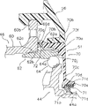
Fig. 3 be its cap assembly mounting portion built-in speed-varying hub analyse and observe partial view.
Fig. 4 is the front elevation of the cover main body of cap assembly.
Fig. 5 is the semisectional view of cap assembly that comprises the V-V line of Fig. 4.
Fig. 6 is the figure that is equivalent to Fig. 3 of other embodiments.
The specific embodiment
In Fig. 1, adopt the bicycle 10 of an embodiment of the present invention, possess as lower member: vehicle frame 12 with vehicle frame 20, suspension 22 and rear-swing arm 24, be fixed on the handlebar 14 on the suspension 22, drive division 16 by gear crank 28 that chain 26, foot-operated PD and a preceding sprocket wheel 28a are installed and built-in speed-varying hub 30 etc. constitute is installed in front-wheel 18 and trailing wheel 19 on suspension 22 and the rear-swing arm 24.Suspension 22 is installed in the front portion of vehicle frame 20, freely turns round around the inclination longitudinal axis.Rear-swing arm 24 has back floatation part 32, and swing is installed in the rear portion of vehicle frame 20 freely.In the rearward end of rear-swing arm 24, be formed with the back claw 24a of the anti-pawl type that is used to install trailing wheel 19, simultaneously, below the claw 24a of back, be formed with the 24b of installation ear of downward extension.
As shown in Figure 1, on front-wheel 18 and trailing wheel 19, before and after disc brake apparatus 34,36 is installed.In addition, built-in speed-varying hub 30 is installed on trailing wheel 19.On the 24b of installation ear of rear-swing arm 24, the chain stretching device 40 that gives chain 26 tension force is installed.
Built-in speed-varying hub 30, as shown in Figure 2, have as lower device: the hub spindle 42 that can be fixed on the trailing wheel 19 on the back claw 24a of rear-swing arm 24, be installed in the roughly barrel-contoured driving body 44 on the hub spindle 42 freely to rotate, be configured in the roughly barrel-contoured hub shell 46 of hub spindle 42 outer circumferential sides, has the speed-changing mechanism 48 that the revolution of driving body 44 on direct of travel is passed to the sun and planet gear of hub shell 46 by many power transfer path, the switching mechanism 50 that switches power transfer path by the mode of selecting, and the cap assembly 51 that is installed in an embodiment of the present invention on the end of hub shell 46.As the built-in speed-varying hub 30 of rear derailleur, for example 8 grades of transmission systems for having 8 power transfer path can pass to hub shell 46 by 8 grades with the revolution of gear crank 28 (Fig. 1) with carrying out speed change.The discal rotor 54 of back disc brake apparatus 36 is installed at an end (Fig. 2 left end) of hub shell 46.On the outer peripheral face of cap assembly 51, wheel hub cover 56 is installed.
Hub spindle 42 utilizes the captive nut 43 of at both ends threads engage not to be fixed on pivotally on the claw 24a of back.Driving body 44, at one end (Fig. 2 right-hand member) has the shaft sleeve part 44a of minor diameter, utilizes the bearing 65 that is installed on the shaft sleeve part 44a to be supported on hub spindle 42 with freely rotating.Back sprocket wheel 52 can not be installed on driving body 44 pivotally.Hub shell 46 has the shell main body 60 of the hub flange 60a, the 60b that are furnished with pair of right and left and with the cartridge 62 on the inner peripheral surface of the end (Fig. 2 right-hand member) that can not rotating mode be connected shell main body 60.Shell main body 60 is the cartridges that have the shaft sleeve part 60c of minor diameter at the other end (Fig. 2 left end), at shaft sleeve part 60c with bearing 63 support cage axle 42 with freely rotating.In addition, discal rotor 54 can not be fixed on the shaft sleeve part 60c pivotally.
On the inner peripheral surface of cartridge 62, as shown in Figure 3, be formed with the ball journal bearing surface 64a that an end of hub shell 46 is supported on freely rotating the bearing 64 of driving body 44.In addition, on the outer peripheral face of cartridge 62, be formed with external thread part 62, in the axial inboard of external thread part 62a and the circular protrusion 62b and the sawtooth 62c of row arrangement.Cap assembly 51 is screwed into is fixed on external thread part 62a.At circular protrusion 62b, an end butt of shell main body 60 and being positioned.At sawtooth 62c, an end inner peripheral surface of shell main body 60 is by riveted and fixed.
Cover main body 70, preferably use the plastic material of rubber-like of polypropylene (PP) geometric ratio softer.Cover main body 70, arrive shown in Figure 5 as Fig. 3, have as lower member: on inner peripheral surface, be provided with the 70b of urceolus portion of internal thread part 70a and be provided with the peristome 70d that can connect at the center and from the inside side wall portion 70c that extends of side of the first end 70f radius vector in the axial outside of the 70b of urceolus portion for the driving body 44 of the interior all sides that are configured in hub shell 46.And, in Fig. 4, only illustrate cover main body 70, the first sealing elements 71 and then be not illustrated out.
The 70b of urceolus portion, axially inboard the second end 70g than other parts slightly radius vector to foreign side's bulging forming, on its outer circumferential side, formed the annular recessed portion 70h that second sealing element 72 is installed.Be formed with side wall portion 70c, so that cover the lateral surface of driving body 44.Side wall portion 70c has the inner cylinder portion 70e that is located at peristome 70d, first sealing element 71 is installed on inner peripheral surface.In addition, side wall portion 70c has the bearing surface 70j that thickness forms than other part heavy back on medial surface.Bearing surface 70j is when being installed in cap assembly 51 on the cartridge 62, with the end face butt in the axial outside of cartridge 62.Inner cylinder portion 70e, forming to the axial outside outstandingly, on its outer peripheral face, separating circumferential compartment of terrain and be formed with 2 groups of double-type instrument fastener 70i, this double-type instrument fastener 70i is used for that card stops instrument when cap assembly 51 is screwed into external thread part 62a, by chamfering in parallel to each other.
The cap assembly 51 of Gou Chenging if finished the assembling of built-in speed-varying hub 30, then before sprocket wheel after the installation 52, is installed on the hub shell 46 like this.When being installed in cap assembly 51 on the hub shell 46, manual revolving hood parts 51 are threaded on the external thread part 62a of cartridge 62 of hub shell 46 internal thread part 70a.After this, proper implements such as engaging spanner etc. utilizes instrument to be screwed into cap assembly 51 on instrument fastener 70i, the end face butt until the axial outside of the bearing surface 70j of side wall portion 70c and cartridge 62.Thus, cap assembly 51 is screwed into and is fixed in the hub shell 46.Be screwed under the fixing state at this, the outer peripheral face butt of first sealing element 71 and the shaft sleeve part 44a of driving body 4, second sealing element 72 is with a front end end face 60d butt of the shell main body 60 of the state of bulging and hub shell 46 slightly.Here, by making internal thread part 70a threads engage, cap assembly 51 is installed on the cartridge 62 of hub shell 46, and thus, the being adjacent to property raising between hub shell and the cap assembly just can make water-proofness be improved without auxiliary material such as grease or parts.
In addition, second sealing element 72 is configured in the second end 70g of the 70b of urceolus portion, the gap of sealing and hub shell 46, therefore, water-proofness is further enhanced.
Other embodiments
(a) in the above-described embodiment, on cap assembly 51, be provided with internal thread part 70a, on the cartridge 62 of hub shell 46, be provided with external thread part 62a, but the present invention do not limit to this.As shown in Figure 6, also can form the 160e of thread barrel portion that extends from an end face 160d, mounting cup parts 151 on the inner peripheral surface of the 160e of thread barrel portion in the shell main body 160 of hub shell 146.In this case, for example, on the inner peripheral surface of the 160e of thread barrel portion, form internal thread part 160f, simultaneously, on the outer peripheral face of the urceolus portion 170 of covering main body 170, form external thread part 170a.In addition, at the end face of the second end 170g of urceolus portion 170, be formed with the sealing mounting groove 170h of ring-type, butt has second sealing element 172 that contacts with an end face 160d of shell main body 160 on sealing mounting groove 170h.Here, use O shape circle as second sealing element 172.Other formation is because identical with above-mentioned embodiment, its explanation of Therefore, omited.
In the cap assembly 151 that constitutes like this, also identical with above-mentioned embodiment, make external thread part 170a and formed internal thread part 160f threads engage, be screwed into the end face butt of cap assembly 151 until the axial outside of the bearing surface 170j of side wall portion 170c and cartridge 162, thus, cap assembly 151 can be screwed into and be fixed on the hub shell 146.In this case, also wheel hub cover 156 can be installed on the outer peripheral face of the 160e of thread barrel portion.
(b) in the above-described embodiment, on side wall portion 70c, be provided with inner cylinder portion 70e, but also inner cylinder portion 70e can be set, but on side wall portion 70c, first sealing element is installed.
(c) in the above-described embodiment, second sealing element 72 is installed water-proofness is further improved, but also second sealing element can be set.Under the situation that second sealing element is not set, also the threaded portion can be arranged to the effective taper thread that leak tightness improves and replace parallel thread.
(d) in the above-described embodiment, mounting portion between hub shell and cap assembly does not use auxiliary material such as grease or parts ground to install, but also can be for example cap assembly and cartridge be under the situation of unoxidizable alloy system in order to prevent sintering etc., and use for example auxiliary material or parts such as grease as required.
(e) also the internal thread part 70a of cap assembly 51 and the internal thread part 62a of cartridge 62 can be made as minus thread.In this case, driving body 44 does not turn round and only has when hub shell 46 is rotating freely turns round, because the antelabium 71a of first sealing element 71 and the friction of driving body 44, when wheel hub 30 is watched on the right side, even cap assembly 51 turns round to anticlockwise direction relatively with respect to hub shell (cartridge 62) 46, screw thread can not relax yet.But, can ignore under the friction situation that causes by antelabium 71a, need not such minus thread.
Description of reference numerals
30 built-in speed-varying hubs
42 hub spindles
44 driving bodies
46 hub shell
48 gears
51 cap assemblies
62 cartridges
The 62a external thread part
70 cover main bodys
The 70a internal thread part
70b urceolus portion
The 70c side wall portion
The 70d peristome
The 70e inner cylinder portion
The 70f first end
The 70g the second end
The 70h annular recessed portion
71 first sealing elements
72 second sealing elements
Claims (8)
1. the cap assembly of a built-in speed-varying hub for bicycle is characterized in that, possesses the cover main body and first sealing element;
Described cover main body has urceolus portion and side wall portion; Described urceolus portion has the threaded portion with the hub shell threads engage of described built-in speed-varying hub; Described side wall portion has the peristome that can connect for the driving body that is configured in side Monday in the described hub shell at the center, and this side wall portion inwardly extends the side from the first end radius vector in the axial outside of described urceolus portion;
Described first sealing element is configured in the side wall portion of described cover main body, with described driving body butt.
2. the cap assembly of built-in speed-varying hub for bicycle as claimed in claim 1 is characterized in that, described side wall portion has the inner cylinder portion that is arranged at described peristome,
Described first sealing element is installed on the inner peripheral surface of described inner cylinder portion.
3. the cap assembly of built-in speed-varying hub for bicycle as claimed in claim 2 is characterized in that, described first sealing element flexibly blocks only on the inner peripheral surface of described inner cylinder portion.
4. as the cap assembly of each described built-in speed-varying hub for bicycle in the claim 1 to 3, it is characterized in that, second sealing element that also possesses the elasticity system, described second sealing element are located on the second end of axial inboard of described urceolus portion, with described hub shell butt.
5. the cap assembly of built-in speed-varying hub for bicycle as claimed in claim 4, it is characterized in that, described second sealing element is fixed in the annular recessed portion on the described the second end that is formed on described urceolus portion, and front end is more side-prominent in axially than described first end.
6. as the cap assembly of each described built-in speed-varying hub for bicycle in the claim 1 to 5, it is characterized in that described cover main body is plastic.
7. built-in speed-varying hub for bicycle is characterized in that possessing:
Hub spindle, described hub spindle can be fixed on the vehicle frame of described bicycle,
Driving body, described driving body roughly is tubular, is installed in freely rotating on the described hub spindle,
Hub shell, described hub shell roughly is tubular, is configured in the outer circumferential side of described hub spindle,
Speed-changing mechanism, described speed-changing mechanism has many power transfer path, is delivered to described hub shell by any revolution with described driving body in described many power transfer path, and
As each described cap assembly in the claim 1 to 6, described cap assembly can be installed and removed at least one end that is installed in described hub shell freely.
8. built-in speed-varying hub for bicycle as claimed in claim 7 is characterized in that described hub shell has external thread part on outer peripheral face,
Described threaded portion, be formed on the inner peripheral surface of described urceolus portion and with the internal thread part of described external thread part threads engage.
Applications Claiming Priority (2)
| Application Number | Priority Date | Filing Date | Title |
|---|---|---|---|
| JP2005220735A JP4157883B2 (en) | 2005-07-29 | 2005-07-29 | Cap member for bicycle internal gear shifting hub |
| JP2005220735 | 2005-07-29 |
Publications (1)
| Publication Number | Publication Date |
|---|---|
| CN1903593A true CN1903593A (en) | 2007-01-31 |
Family
ID=37387425
Family Applications (1)
| Application Number | Title | Priority Date | Filing Date |
|---|---|---|---|
| CNA2006100946428A Pending CN1903593A (en) | 2005-07-29 | 2006-06-20 | Cap member for internally geared bicycle hub |
Country Status (6)
| Country | Link |
|---|---|
| US (1) | US7478885B2 (en) |
| EP (1) | EP1747986B1 (en) |
| JP (1) | JP4157883B2 (en) |
| CN (1) | CN1903593A (en) |
| DE (1) | DE602006002849D1 (en) |
| TW (1) | TWI300043B (en) |
Cited By (1)
| Publication number | Priority date | Publication date | Assignee | Title |
|---|---|---|---|---|
| CN111845199A (en) * | 2019-04-26 | 2020-10-30 | 株式会社岛野 | Wheel unit for human-powered vehicle and wheel assembly for human-powered vehicle |
Families Citing this family (34)
| Publication number | Priority date | Publication date | Assignee | Title |
|---|---|---|---|---|
| US7011600B2 (en) | 2003-02-28 | 2006-03-14 | Fallbrook Technologies Inc. | Continuously variable transmission |
| JP4974896B2 (en) | 2004-10-05 | 2012-07-11 | フォールブルック テクノロジーズ インコーポレイテッド | Continuously variable transmission |
| DE602005004505T2 (en) * | 2005-02-28 | 2009-02-05 | Shimano Inc., Sakai | Cover for a bicycle hub shifter |
| EP1945490B1 (en) | 2005-10-28 | 2018-12-05 | Fallbrook Intellectual Property Company LLC | Electromotive drives |
| EP1954959B1 (en) | 2005-11-22 | 2013-05-15 | Fallbrook Intellectual Property Company LLC | Continuously variable transmission |
| CA2930483C (en) * | 2005-12-09 | 2017-11-07 | Fallbrook Intellectual Property Company Llc | Continuously variable transmission |
| EP1811202A1 (en) | 2005-12-30 | 2007-07-25 | Fallbrook Technologies, Inc. | A continuously variable gear transmission |
| CN102269056B (en) | 2006-06-26 | 2013-10-23 | 福博科技术公司 | Continuously variable transmission |
| US8738255B2 (en) | 2007-02-01 | 2014-05-27 | Fallbrook Intellectual Property Company Llc | Systems and methods for control of transmission and/or prime mover |
| CN104121345B (en) | 2007-02-12 | 2017-01-11 | 福博科知识产权有限责任公司 | Continuously variable transmission and method therefor |
| CN103438207B (en) | 2007-02-16 | 2016-08-31 | 福博科技术公司 | Unlimited speed changing type buncher, buncher and method, assembly, sub-component and parts |
| CN105626801B (en) | 2007-04-24 | 2019-05-28 | 福博科知识产权有限责任公司 | Electric traction drives |
| US8641577B2 (en) | 2007-06-11 | 2014-02-04 | Fallbrook Intellectual Property Company Llc | Continuously variable transmission |
| CA2692476C (en) | 2007-07-05 | 2017-11-21 | Fallbrook Technologies Inc. | Continuously variable transmission |
| US8996263B2 (en) | 2007-11-16 | 2015-03-31 | Fallbrook Intellectual Property Company Llc | Controller for variable transmission |
| WO2009085773A1 (en) | 2007-12-21 | 2009-07-09 | Fallbrook Technologies Inc. | Automatic transmissions and methods therefor |
| US8313405B2 (en) | 2008-02-29 | 2012-11-20 | Fallbrook Intellectual Property Company Llc | Continuously and/or infinitely variable transmissions and methods therefor |
| US8317651B2 (en) | 2008-05-07 | 2012-11-27 | Fallbrook Intellectual Property Company Llc | Assemblies and methods for clamping force generation |
| US8535199B2 (en) | 2008-06-06 | 2013-09-17 | Fallbrook Intellectual Property Company Llc | Infinitely variable transmissions, continuously variable transmissions, methods, assemblies, subassemblies, and components therefor |
| EP2304272B1 (en) | 2008-06-23 | 2017-03-08 | Fallbrook Intellectual Property Company LLC | Continuously variable transmission |
| WO2010017242A1 (en) | 2008-08-05 | 2010-02-11 | Fallbrook Technologies Inc. | Methods for control of transmission and prime mover |
| US8469856B2 (en) | 2008-08-26 | 2013-06-25 | Fallbrook Intellectual Property Company Llc | Continuously variable transmission |
| US20100052414A1 (en) * | 2008-09-03 | 2010-03-04 | Curt Leaverton | Bearing Seal Assembly |
| US8167759B2 (en) | 2008-10-14 | 2012-05-01 | Fallbrook Technologies Inc. | Continuously variable transmission |
| CA2756273C (en) | 2009-04-16 | 2017-06-27 | Fallbrook Technologies Inc. | Stator assembly and shifting mechanism for a continuously variable transmission |
| US8512195B2 (en) | 2010-03-03 | 2013-08-20 | Fallbrook Intellectual Property Company Llc | Infinitely variable transmissions, continuously variable transmissions, methods, assemblies, subassemblies, and components therefor |
| US8888643B2 (en) | 2010-11-10 | 2014-11-18 | Fallbrook Intellectual Property Company Llc | Continuously variable transmission |
| WO2013112408A1 (en) | 2012-01-23 | 2013-08-01 | Fallbrook Intellectual Property Company Llc | Infinitely variable transmissions, continuously variable transmissions methods, assemblies, subassemblies, and components therefor |
| CA2909565A1 (en) | 2013-04-19 | 2014-10-23 | Fallbrook Intellectual Property Company Llc | Continuously variable transmission |
| US10047861B2 (en) | 2016-01-15 | 2018-08-14 | Fallbrook Intellectual Property Company Llc | Systems and methods for controlling rollback in continuously variable transmissions |
| CN109154368B (en) | 2016-03-18 | 2022-04-01 | 福博科知识产权有限责任公司 | Continuously variable transmission, system and method |
| US10023266B2 (en) | 2016-05-11 | 2018-07-17 | Fallbrook Intellectual Property Company Llc | Systems and methods for automatic configuration and automatic calibration of continuously variable transmissions and bicycles having continuously variable transmissions |
| US11215268B2 (en) | 2018-11-06 | 2022-01-04 | Fallbrook Intellectual Property Company Llc | Continuously variable transmissions, synchronous shifting, twin countershafts and methods for control of same |
| US11174922B2 (en) | 2019-02-26 | 2021-11-16 | Fallbrook Intellectual Property Company Llc | Reversible variable drives and systems and methods for control in forward and reverse directions |
Family Cites Families (25)
| Publication number | Priority date | Publication date | Assignee | Title |
|---|---|---|---|---|
| US1878528A (en) * | 1931-10-30 | 1932-09-20 | Murray Ohio Mfg Co | Wheel construction |
| DE3331557A1 (en) * | 1983-09-01 | 1985-03-21 | Fichtel & Sachs Ag, 8720 Schweinfurt | DRIVE HUB WITH AXLE FOR BICYCLES OR THE LIKE |
| JP3140265B2 (en) * | 1993-06-29 | 2001-03-05 | 株式会社シマノ | Interior gear hub for bicycle |
| JP3423756B2 (en) * | 1993-12-16 | 2003-07-07 | 株式会社シマノ | Operation structure of bicycle motion device |
| JP3080534B2 (en) * | 1994-04-28 | 2000-08-28 | 株式会社シマノ | Interior transmission |
| US5492392A (en) * | 1995-05-01 | 1996-02-20 | Chen; Ava | Derailleur guard |
| JP3090251B2 (en) | 1996-02-20 | 2000-09-18 | 株式会社シマノ | Front hub for bicycle |
| JP2914909B2 (en) * | 1996-03-15 | 1999-07-05 | 株式会社シマノ | Gearbox for bicycle transmission |
| JP3097904B2 (en) * | 1997-01-10 | 2000-10-10 | 株式会社シマノ | Bicycle hub |
| JP3142250B2 (en) * | 1997-06-27 | 2001-03-07 | 株式会社シマノ | Bicycle bearings and bicycle rotating parts using the same |
| JP3165673B2 (en) * | 1997-08-08 | 2001-05-14 | 株式会社シマノ | Interior gear hub for bicycle |
| KR100258784B1 (en) * | 1998-01-20 | 2000-06-15 | 마재열 | Power changing apparatus of bicycle hub |
| US6325386B1 (en) * | 1999-03-30 | 2001-12-04 | Shimano, Inc. | Rotatable seal assembly for a bicycle hub transmission |
| DE19915714A1 (en) * | 1999-04-08 | 2000-10-12 | Sram De Gmbh | Hub for bicycles |
| TW448854U (en) | 1999-05-13 | 2001-08-01 | Mavic Sa | Slotted flange bicycle rear hub |
| US6352314B1 (en) * | 2000-01-31 | 2002-03-05 | Shimano Inc. | Bicycle hub for disc brake |
| US6607465B1 (en) * | 2000-03-10 | 2003-08-19 | Shimano, Inc. | Bicycle hub transmission with a guiding member for a sun gear |
| DE20013400U1 (en) * | 2000-08-03 | 2000-12-21 | Kun Teng Industry Co | Hub power transmission mechanism with a sealing element |
| IT1320644B1 (en) * | 2000-09-15 | 2003-12-10 | Campagnolo Srl | WHEEL HUB FOR BICYCLE. |
| DE20101377U1 (en) | 2001-01-26 | 2001-03-29 | Kun Teng Industry Co | Bicycle hub provided with a sealing element to prevent the ingress of dust |
| US6558288B2 (en) * | 2001-05-18 | 2003-05-06 | Shimano, Inc. | Internal transmission device with automatic shift mechanism for a bicycle |
| US6641500B2 (en) * | 2001-12-27 | 2003-11-04 | Shimano, Inc. | Bicycle hub transmission with a power control mechanism for a shift assist mechanism |
| US6875150B2 (en) | 2001-12-27 | 2005-04-05 | Shimano, Inc. | Multiple piece planet gear carrier for a bicycle hub transmission |
| EP1452438B1 (en) * | 2003-02-28 | 2013-02-27 | Shimano Inc. | An internal hub transmission for a bicycle |
| US7029075B2 (en) * | 2004-02-20 | 2006-04-18 | Shimano Inc. | Bicycle hub sealing assembly |
-
2005
- 2005-07-29 JP JP2005220735A patent/JP4157883B2/en not_active Expired - Fee Related
-
2006
- 2006-04-20 US US11/407,108 patent/US7478885B2/en not_active Expired - Fee Related
- 2006-05-25 TW TW095118546A patent/TWI300043B/en not_active IP Right Cessation
- 2006-06-20 CN CNA2006100946428A patent/CN1903593A/en active Pending
- 2006-07-26 EP EP06015592A patent/EP1747986B1/en not_active Expired - Fee Related
- 2006-07-26 DE DE602006002849T patent/DE602006002849D1/en active Active
Cited By (2)
| Publication number | Priority date | Publication date | Assignee | Title |
|---|---|---|---|---|
| CN111845199A (en) * | 2019-04-26 | 2020-10-30 | 株式会社岛野 | Wheel unit for human-powered vehicle and wheel assembly for human-powered vehicle |
| CN111845199B (en) * | 2019-04-26 | 2024-04-09 | 株式会社岛野 | Wheel unit for a manually driven vehicle and wheel assembly for a manually driven vehicle |
Also Published As
| Publication number | Publication date |
|---|---|
| JP4157883B2 (en) | 2008-10-01 |
| JP2007030820A (en) | 2007-02-08 |
| US7478885B2 (en) | 2009-01-20 |
| EP1747986B1 (en) | 2008-09-24 |
| EP1747986A3 (en) | 2007-08-01 |
| US20070045079A1 (en) | 2007-03-01 |
| DE602006002849D1 (en) | 2008-11-06 |
| TW200706446A (en) | 2007-02-16 |
| TWI300043B (en) | 2008-08-21 |
| EP1747986A2 (en) | 2007-01-31 |
Similar Documents
| Publication | Publication Date | Title |
|---|---|---|
| CN1903593A (en) | Cap member for internally geared bicycle hub | |
| CN1309965C (en) | Bearing module of bicycle | |
| CN1712306A (en) | Bicycle sprocket | |
| CN1272215C (en) | Multi-level chain support of bicycle | |
| CN107336794B (en) | Electric auxiliary bicycle | |
| CN1185114C (en) | Bicycle hub with closely linked ratchet and detachable free wheel | |
| CN1265997C (en) | Bicycle chain wheel with side lug for multi-chain wheel assemble | |
| CN1861475A (en) | Rear sprocket for bicycle transmission | |
| CN1579874A (en) | Bicycle sprocket | |
| CN1721138A (en) | Bicycle crank assembly and assembly tools | |
| CN1449946A (en) | Tandem axle power divider assembly with inboard slip driveshaft connection | |
| CN1102519C (en) | Bicycle suspension assembly | |
| CN1657329A (en) | Bicycle hub | |
| CN101059154A (en) | Clutch actuator, engine unit and bestriding type vehicle | |
| CN1903595A (en) | Fastening mechanism for bicycle hub | |
| CN1269664C (en) | Saddle-type vehicle carrying with differential limiting device | |
| CN202215895U (en) | Motor decorative cover installation structure | |
| CN1903592A (en) | Bicycle hub cover | |
| CN1817733A (en) | An internal transmission for a bicycle | |
| CN1091048C (en) | Sealing structure of power unit transmission case for vehicle | |
| US11951788B2 (en) | Bearing unit for a suspension strut of a motor vehicle and method for installing a bearing unit on a motor vehicle body part | |
| EP1961582B1 (en) | Vehicle wheel | |
| CN1522879A (en) | Rear hub for bicycle | |
| CN211167274U (en) | Bicycle pedal | |
| CN1482353A (en) | Pinion-shaft support structure for starter in power unit |
Legal Events
| Date | Code | Title | Description |
|---|---|---|---|
| C06 | Publication | ||
| PB01 | Publication | ||
| C10 | Entry into substantive examination | ||
| SE01 | Entry into force of request for substantive examination | ||
| C02 | Deemed withdrawal of patent application after publication (patent law 2001) | ||
| WD01 | Invention patent application deemed withdrawn after publication |