CN1846292A - Unipolar electrostatic quadrupole lens and switching methods for charged beam transport - Google Patents
Unipolar electrostatic quadrupole lens and switching methods for charged beam transport Download PDFInfo
- Publication number
- CN1846292A CN1846292A CNA200480025420XA CN200480025420A CN1846292A CN 1846292 A CN1846292 A CN 1846292A CN A200480025420X A CNA200480025420X A CN A200480025420XA CN 200480025420 A CN200480025420 A CN 200480025420A CN 1846292 A CN1846292 A CN 1846292A
- Authority
- CN
- China
- Prior art keywords
- pair
- electrode
- quadrupole lens
- ion beam
- lens
- Prior art date
- Legal status (The legal status is an assumption and is not a legal conclusion. Google has not performed a legal analysis and makes no representation as to the accuracy of the status listed.)
- Granted
Links
Images


Classifications
-
- H—ELECTRICITY
- H01—ELECTRIC ELEMENTS
- H01J—ELECTRIC DISCHARGE TUBES OR DISCHARGE LAMPS
- H01J37/00—Discharge tubes with provision for introducing objects or material to be exposed to the discharge, e.g. for the purpose of examination or processing thereof
- H01J37/02—Details
- H01J37/04—Arrangements of electrodes and associated parts for generating or controlling the discharge, e.g. electron-optical arrangement or ion-optical arrangement
- H01J37/10—Lenses
- H01J37/12—Lenses electrostatic
-
- H—ELECTRICITY
- H10—SEMICONDUCTOR DEVICES; ELECTRIC SOLID-STATE DEVICES NOT OTHERWISE PROVIDED FOR
- H10P—GENERIC PROCESSES OR APPARATUS FOR THE MANUFACTURE OR TREATMENT OF DEVICES COVERED BY CLASS H10
- H10P30/00—Ion implantation into wafers, substrates or parts of devices
- H10P30/20—Ion implantation into wafers, substrates or parts of devices into semiconductor materials, e.g. for doping
-
- H—ELECTRICITY
- H01—ELECTRIC ELEMENTS
- H01J—ELECTRIC DISCHARGE TUBES OR DISCHARGE LAMPS
- H01J37/00—Discharge tubes with provision for introducing objects or material to be exposed to the discharge, e.g. for the purpose of examination or processing thereof
- H01J37/02—Details
- H01J37/04—Arrangements of electrodes and associated parts for generating or controlling the discharge, e.g. electron-optical arrangement or ion-optical arrangement
- H01J37/153—Electron-optical or ion-optical arrangements for the correction of image defects, e.g. stigmators
-
- H—ELECTRICITY
- H01—ELECTRIC ELEMENTS
- H01J—ELECTRIC DISCHARGE TUBES OR DISCHARGE LAMPS
- H01J37/00—Discharge tubes with provision for introducing objects or material to be exposed to the discharge, e.g. for the purpose of examination or processing thereof
- H01J37/30—Electron-beam or ion-beam tubes for localised treatment of objects
- H01J37/317—Electron-beam or ion-beam tubes for localised treatment of objects for changing properties of the objects or for applying thin layers thereon, e.g. for ion implantation
- H01J37/3171—Electron-beam or ion-beam tubes for localised treatment of objects for changing properties of the objects or for applying thin layers thereon, e.g. for ion implantation for ion implantation
-
- H—ELECTRICITY
- H01—ELECTRIC ELEMENTS
- H01J—ELECTRIC DISCHARGE TUBES OR DISCHARGE LAMPS
- H01J2237/00—Discharge tubes exposing object to beam, e.g. for analysis treatment, etching, imaging
- H01J2237/04—Means for controlling the discharge
- H01J2237/047—Changing particle velocity
- H01J2237/0473—Changing particle velocity accelerating
- H01J2237/04735—Changing particle velocity accelerating with electrostatic means
- H01J2237/04737—Changing particle velocity accelerating with electrostatic means radio-frequency quadrupole [RFQ]
-
- H—ELECTRICITY
- H01—ELECTRIC ELEMENTS
- H01J—ELECTRIC DISCHARGE TUBES OR DISCHARGE LAMPS
- H01J2237/00—Discharge tubes exposing object to beam, e.g. for analysis treatment, etching, imaging
- H01J2237/04—Means for controlling the discharge
- H01J2237/049—Focusing means
- H01J2237/0492—Lens systems
- H01J2237/04924—Lens systems electrostatic
Landscapes
- Chemical & Material Sciences (AREA)
- Analytical Chemistry (AREA)
- Particle Accelerators (AREA)
Abstract
本发明降低了射束电流的损失,特别是对于低能量离子束传输。本发明使用单极静电四极透镜取代传统的正和负双电位(双极)四极透镜来作为一线性加速器中的射束聚焦元件,其中减少了其中的射束电流损失。此外本发明也包括用于在双极配线和单极配线间切换的系统和方法。This invention reduces beam current loss, particularly for low-energy ion beam transmission. It utilizes a monopolar electrostatic quadrupole lens instead of a conventional positive and negative dual-potential (bipolar) quadrupole lens as the beam focusing element in a linear accelerator, thereby reducing beam current loss. Furthermore, the invention includes systems and methods for switching between bipolar and monopolar wiring.
Description
发明领域field of invention
本发明一般地涉及离子植入装置,且更特别地,涉及一单极静电四极透镜及在一离子植入系统中可使用的该透镜的使用。The present invention relates generally to ion implantation apparatus, and more particularly, to a unipolar electrostatic quadrupole lens and the use of the lens usable in an ion implantation system.
发明背景Background of the invention
离子植入是一种过程,其在半导体器件制造中被用于选择地植入掺杂到半导体和/或晶片材料中。对离子植入,掺杂原子/分子被离子化和隔离、加速、形成射束且扫过一晶片。掺杂离子物理地轰击晶片,进入表面且停在表面之下。Ion implantation is a process that is used in semiconductor device fabrication to selectively implant dopants into semiconductor and/or wafer materials. For ion implantation, dopant atoms/molecules are ionized and isolated, accelerated, beamed and swept across a wafer. The dopant ions physically bombard the wafer, enter the surface and settle below the surface.
一离子植入系统是精密子系统的集合,每一子系统执行一特殊作用于掺杂离子上。掺杂元素-在气态或固态下-被置放于离子化腔内且借助合适的离子化过程被离子化。在一示例过程中,腔维持在低压(真空)下。一灯丝安置于腔中且加热至从灯丝源产生电子的状况。带负电荷的电子被吸引至也位于腔中的一带相反电荷的阳极。在从灯丝行进至阳极的时间内,电子和掺杂源元素(例如原子或分子)碰撞,且从分子状态的元素中产生许多带正电荷的离子。An ion implantation system is a collection of sophisticated subsystems, each of which performs a specific action on dopant ions. Dopant elements - in gaseous or solid state - are placed in the ionization chamber and ionized by means of a suitable ionization process. During an example process, the chamber is maintained at a low pressure (vacuum). A filament is positioned in the cavity and heated to a condition where electrons are generated from the filament source. The negatively charged electrons are attracted to an oppositely charged anode also located in the cavity. In the time it takes to travel from the filament to the anode, electrons collide with dopant source elements (such as atoms or molecules) and generate many positively charged ions from the elements in molecular state.
一般除了所需的掺杂离子外,也产生其他正离子。所需的掺杂离子借助被称为分析、质量分析、选择或离子分离的过程而从离子中选择。选择是通过使用一产生磁场的质量分析器(mass analyzer)而完成的,其中从离子化腔来的离子行进通过所述的磁场。离子以相当高的速度离开离子化腔且借助磁场弯曲成弧状。弧状的半径由个别离子质量、速度和磁场的强度所支配。分析器的出口只允许一种离子-所需的掺杂离子-离开质量分析器。In general, other positive ions are produced in addition to the desired dopant ions. The desired dopant ions are selected from the ions by a process known as analysis, mass analysis, selection or ion separation. Selection is accomplished using a mass analyzer that generates a magnetic field through which ions from the ionization chamber travel. Ions leave the ionization chamber at a relatively high velocity and are bent into an arc by the magnetic field. The radius of the arc is governed by the individual ion mass, velocity and strength of the magnetic field. The exit of the analyzer allows only one type of ion - the desired dopant ion - to leave the mass analyzer.
一加速系统-被称为线性加速器-被使用于一些系统中,以便加速所需的掺杂离子至预定能量以进入晶片表面。对加速而言,系统一般地为线性设计,其具有被环形供电的电极和延伸于其轴上的四极透镜。四极透镜以负和正电位供电。当掺杂离子进入其中,该掺杂离子便借助被供电的电极被加速穿过且借助四极透镜而选择地聚焦(成射束)。An acceleration system - known as a linear accelerator - is used in some systems to accelerate the desired dopant ions to a predetermined energy to enter the wafer surface. For acceleration, the system is generally a linear design with electrodes powered by rings and a quadrupole lens extending on its axis. The quadrupole lenses are powered with negative and positive potentials. When dopant ions enter therein, they are accelerated through by means of powered electrodes and selectively focused (beamed) by means of quadrupole lenses.
接下来,掺杂离子在终点站被导向晶片。该晶片可以置放于以一预定转速旋转的过程托盘上。掺杂离子-以射束-以一特定的射束电流撞击晶片。Next, dopant ions are directed toward the wafer at the final station. The wafer may be placed on a process tray that rotates at a predetermined rotational speed. The dopant ions - in the beam - strike the wafer with a specific beam current.
一般地,当掺杂离子通过加速系统时,射束电流有一基本的损失。这种损失在低能量时特别地高。这样的射束电流损失可增加实施离子植入的成本、复杂度和困难度。此外,这样的射束电流损失可能限制加速系统和因此还有该加速系统所属的离子植入系统的操作范围。因此需要降低通过加速系统的射束电流损失。Typically, there is a substantial loss of beam current as the dopant ions pass through the accelerating system. This loss is particularly high at low energies. Such beam current loss can increase the cost, complexity and difficulty of performing ion implantation. Furthermore, such beam current loss may limit the operating range of the acceleration system and thus the ion implantation system to which the acceleration system belongs. There is therefore a need to reduce beam current losses through the acceleration system.
发明概要Summary of the invention
为了提供本发明一个或多个方面的基本理解,紧接着描述一简单概要。该概要并非本发明广泛的概述,也非意欲指出本发明的重要或关键要点,也非记载其范围。而概要的主要意图是以一简单的形式描述一些本发明的方案,以当作稍后呈现的更详细说明的开场白。A brief summary follows, in order to provide a basic understanding of one or more aspects of the invention. This summary is not an extensive overview of the invention, nor is it intended to identify key or critical points of the invention nor delineate its scope. Rather, the main intent of the Summary is to describe some aspects of the invention in a simplified form as a prelude to the more detailed description presented later.
本发明降低了射束电流损失,特别是对于低能量离子植入。本发明使用静电四极透镜,每一透镜借助单极电源而非双极电源被激励,以便传输一低能量离子束通过一离子植入机的线性加速器部分。尤其是,此方法被用于当加速设为零时。结果,离子植入系统能够操作在低能量下,因此扩大了离子植入系统的操作范围。此外本发明也包括用于在双极配线和单极配线间切换的系统和方法。The invention reduces beam current loss, especially for low energy ion implantation. The present invention uses electrostatic quadrupole lenses, each lens energized by a unipolar power supply rather than a bipolar power supply, in order to transmit a low energy ion beam through the linear accelerator portion of an ion implanter. In particular, this method is used when acceleration is set to zero. As a result, the ion implantation system is able to operate at low energies, thus expanding the operating range of the ion implantation system. Additionally, the present invention also includes systems and methods for switching between bipolar wiring and monopolar wiring.
为完成前述和相关目的,本发明包括的特点在下面将完全地描述且特别地在权利要求中指出。下面的说明和附图详细地讲述了本发明特定的说明性观点和实施。然而它们只是指示出本发明原理可以应用的各种方式中的某些而已。配合参考附图,从紧接的本发明详细说明中,本发明其他目的、优点和新颖的特点将会变得显而易见。To the accomplishment of the foregoing and related ends, the invention comprises the features hereinafter fully described and particularly pointed out in the claims. The following description and drawings set forth in detail certain illustrative aspects and implementations of the invention. They are indicative, however, of but a few of the various ways in which the principles of the invention may be applied. Other objects, advantages and novel features of the present invention will become apparent from the ensuing detailed description of the invention when taken together with reference to the accompanying drawings.
附图简述Brief description of the drawings
图1为根据本发明一方面的高能量离子植入系统图。FIG. 1 is a diagram of a high energy ion implantation system according to one aspect of the present invention.
图2为根据本发明一方面的模块化线性加速器的透视图。2 is a perspective view of a modular linear accelerator according to an aspect of the invention.
图3为示例性的常规正和负双极静电四极透镜图。Figure 3 is a diagram of an exemplary conventional positive and negative bipolar electrostatic quadrupole lens.
图4为根据本发明一方面的负电位单极静电四极透镜图。4 is a diagram of a negative potential unipolar electrostatic quadrupole lens according to one aspect of the present invention.
图5为根据本发明一方面的正电位单极静电四极透镜图。5 is a diagram of a positive potential unipolar electrostatic quadrupole lens according to one aspect of the present invention.
图6为根据本发明一方面的静电四极透镜的切换电路图。6 is a switching circuit diagram of an electrostatic quadrupole lens according to one aspect of the present invention.
图7为根据本发明一方面的静电四极透镜的切换电路图。7 is a switching circuit diagram of an electrostatic quadrupole lens according to one aspect of the present invention.
图8为根据本发明一方面的产生所需离子束的方法流程图。8 is a flowchart of a method of generating a desired ion beam in accordance with an aspect of the present invention.
发明详述Detailed description of the invention
现在将参照附图说明本发明,其中贯穿全说明书使用相似元件符号来参照相似元件。本领域技术人员应当理解,本发明并不限于之后所说明和阐述的示例实施例和方面。The present invention will now be described with reference to the drawings, wherein like reference numerals are used to refer to like elements throughout. It will be appreciated by those skilled in the art that the present invention is not limited to the exemplary embodiments and aspects illustrated and illustrated hereinafter.
本发明通过降低通过高能量植入机的线性加速部分的射束电流的衰减来方便离子植入。运用一串的单极四极透镜,而非双极四极透镜。单极四极透镜的使用降低了射束电流损失,且可以扩大离子植入系统的操作范围。The present invention facilitates ion implantation by reducing the attenuation of beam current through the linear acceleration portion of a high energy implanter. Use a series of single-pole quadrupole lenses instead of double-pole quadrupole lenses. The use of a single quadrupole lens reduces beam current loss and can extend the operating range of the ion implantation system.
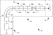
从图1开始,说明根据本发明一方面的示例性高能量植入系统10的图解。系统10具一终端12、一束线组件14和一终点站16。终端12包括由一高压电源22供电的一离子源20。离子源20产生提供给束线组件14的一离子束24。然后离子束24在终点站16中导向目标晶片30。包括一质量分析磁体26和一射频(RF)线性加速器(linac)28的束线组件14则调整离子束24。线性加速器28包括一串的加速模块28a-28n,每一加速模块可以进一步加速离子以超越它们从前面的模块所获得的能量。可借助一高射频电压-典型地借助谐振法被产生以维持所需适度的平均功率-单独地激励加速模块。质量分析磁体26只让适合的电荷/质量比的离子通过线性加速器28。Beginning with FIG. 1 , a diagram of an exemplary high
在本例的系统10中的线性加速模块28a-28n单独地包括一射频放大器、一谐振器、一可激励电极和一单极静电四极透镜-也称为四极透镜。谐振器在一适当频率(例如以大约0-150kV的电压,在大约3-30MHz范围下)操作来加速离子束24至所需能量(例如每电荷态超过一百万电子伏特)。当离子束24通过各个加速模块或级28时,离子被加速和倾向于散开。The
单极静电四极透镜单独地包括位于中心轴周围的四个等间隔的电极,且产生和离子束24的路径横切的四极场。第一对电极-互相相对地置放-为负电位且第二对电极为接地电位。由于产生的静电场,单极静电四极透镜对离子束24具有聚焦效果。第一对透镜-在一实施例中-在垂直平面上聚焦且在水平平面上散焦,而第二对透镜在水平平面上聚焦且在垂直平面上散焦。通过调整施加给所有线性加速模块28a-28n的单极静电四极透镜的负电位,离子束24的去散(despread)可以降低且离子束24可以聚焦成所需的形状。The unipolar electrostatic quadrupole lens alone comprises four equally spaced electrodes located around a central axis and produces a quadrupole field transverse to the path of the
因为少了典型地在常规静电四极透镜中使用的正电位,所以单极静电四极透镜的使用减缓了离子束24中和的降低。结果离子束24的射束电流比使用常规正和负双极静电四极透镜的常规离子植入系统中的射束电流要大。The use of unipolar electrostatic quadrupole lenses slows down the reduction in
图2提供根据本发明一方面的示例性模块化的线性加速模块或级228的透视图。一直流离子束224a沿着一射束路径226提供给加速器228(例如来自于前面的质量分析磁体,未画出)。举例来说,直流离子束224a可以包括细长狭缝形状,其沿着路径226通过一具有垂直细长狭缝232的进入开口230。离子束224a经由两组匹配的四极装置234和相应接地的电极236而形成为大致圆形(未画出),其中每一接地电极236包括一处在路径226上的圆形开口238。本发明的四极装置234包括一对单极静电四极透镜,其中第一对在垂直平面上聚焦且第二对在水平平面上聚焦。FIG. 2 provides a perspective view of an exemplary modular linear acceleration module or
线性加速器228还包括两个或更多加速模块或级228a、228b、...228n-其中n为整数,其中的两个(例如级228a和228b)在图2中被示出。每一加速模块228n进一步加速来自于离子束224的离子以超越它们从前面的模块所获得的能量。可借助用一电源和谐振器(未画出)产生的高射频电压单独地激励加速模块228n。加速模块228a包括沿着路径226在一可激励电极248之前和之后置放的一对接地电极246,其中可激励电极248可被一适当的射频能量源和谐振器(未画出)激励以完成射束路径226上离子束224a内的离子加速。接地电极246一般和可激励电极248为等间距,以便提供它们之间一般相等的第一和第二间隙250a和250b。相似地,第二加速模块或级228b包括沿着路径226在一第二可激励电极258的前面置放的第一接地电极256。
也是一单极静电四极透镜的四极装置264可位于路径226上的第一和第二加速级228a和228b间,以在离子束224通过连续加速级228时提供该离子束的径向聚焦。加速器228可包括进一步的加速级或模块(未画出),由此一离子束224b可加速至高于向加速器228所提供的直流离子束224a的能量级。虽然只有一四极透镜264在图2中用来说明级228a,应该了解的是,可以类似于四极装置234而提供一对这样的透镜。此外,虽然在一实施例中,线性加速器的每一级228a至228n使用单极四极透镜,但本发明也可预期变型方案,其中这样的四极装置并未被用于所有的级。
图3为说明示例性常规正和负双极静电四极透镜300的图解。透镜300包括一提供本质上幅度相同的正电压和负电压的电源302。此外透镜300也包括一对互相相对地置放的负电极304、306和一对互相相对地置放的正电极308、310,其中电极304、306、308和310在中心点周围被等间距地隔开。FIG. 3 is a diagram illustrating an exemplary conventional positive and negative bipolar electrostatic quadrupole lens 300 . Lens 300 includes a power supply 302 that provides positive and negative voltages of substantially the same magnitude. In addition, the lens 300 also includes a pair of oppositely disposed negative electrodes 304, 306 and a pair of oppositely disposed positive electrodes 308, 310, wherein the electrodes 304, 306, 308, and 310 are spaced equidistantly about a central point. separated.
负电极对304和306连接至电源302且接收负电压。结果负电极对304和306偏压至负电压值。此外正电极对308和310连接至电源302且接收正电压,因此偏压至正电压。电极(304、306、308和310)产生四极静电场以选择地聚焦和散焦通过中心点的一离子束。举例来说,一离子束中的带正电荷的离子被在箭头312指示的方向上的场加速,造成离子束在Y方向聚焦且在X方向散焦。获得的聚焦/散焦量为偏压电极(304、306、308和310)的正电压和负电压幅度的函数。Negative electrode pair 304 and 306 are connected to power source 302 and receive a negative voltage. As a result, negative electrode pair 304 and 306 are biased to a negative voltage value. In addition, positive electrode pair 308 and 310 are connected to power supply 302 and receive a positive voltage, thus biased to a positive voltage. Electrodes (304, 306, 308 and 310) generate quadrupole electrostatic fields to selectively focus and defocus a beam of ions passing through the central point. For example, positively charged ions in an ion beam are accelerated by the field in the direction indicated by arrow 312, causing the ion beam to focus in the Y direction and defocus in the X direction. The amount of focus/defocus obtained is a function of the magnitude of the positive and negative voltages of the bias electrodes (304, 306, 308 and 310).
现在翻到图4,其绘出根据本发明一方面的一负单极静电四极透镜400的图解。透镜400包括一负电极对404、406和一接地电极对408、410。Turning now to FIG. 4, there is depicted a diagram of a negative unipolar electrostatic quadrupole lens 400 in accordance with an aspect of the present invention. Lens 400 includes a pair of negative electrodes 404,406 and a pair of ground electrodes 408,410.
电源402输送一负电压给负电极对404、406。接地电极对408、410连接至接地,典型地经过一低阻路径。因此负电极对偏压至负电压值,且接地电极对408、410偏压至接地。以类似图3中说明的方式,电极产生四极静电场,其中射束于一平面上聚焦且同时于第二垂直的平面上散焦。The power supply 402 supplies a negative voltage to the negative electrode pair 404,406. The ground electrode pair 408, 410 is connected to ground, typically via a low resistance path. The negative electrode pair is thus biased to a negative voltage value, and the ground electrode pair 408, 410 is biased to ground. In a manner similar to that illustrated in FIG. 3, the electrodes generate a quadrupole electrostatic field in which the beam is focused in one plane and simultaneously defocused in a second perpendicular plane.
虽然该现象的完全了解尚未被完全理解,但和图3双极正和负静电四极透镜300相比,单极静电四极透镜400降低了射束电流的损失。相信是因为对离子束中带正电荷的离子加剧了空间电荷效应而使得正电位电极减少了射束电流的损失。在任何情况下,使用图4的单极静电透镜,在某些低能量情形下已经观测到最终射束电流的两倍增加。Although a complete understanding of this phenomenon is not yet fully understood, the unipolar electrostatic quadrupole lens 400 reduces beam current loss compared to the bipolar positive and negative electrostatic quadrupole lens 300 of FIG. 3 . Positive potential electrodes are believed to reduce beam current losses due to exacerbating space charge effects on positively charged ions in the ion beam. In any case, using the monopolar electrostatic lens of Figure 4, a two-fold increase in final beam current has been observed in certain low energy situations.
现在翻到图5,其绘出根据本发明一方面的一正单极静电四极透镜500的图解。透镜500包括第一正电极504、第二正电极506、第一接地电极508和第二接地电极510。Turning now to FIG. 5, there is depicted a diagram of a positive unipolar electrostatic quadrupole lens 500 in accordance with an aspect of the present invention. The lens 500 includes a first positive electrode 504 , a second positive electrode 506 , a first ground electrode 508 and a second ground electrode 510 .
电源502输送一正电压给第一正电极504和第二正电极506。第一接地电极508和第二接地电极510连接至接地。因此第一正电极504和第二正电极506偏压至正电压值,且第一接地电极508和第二接地电极510偏压至接地电压值。电极从电极-两正和两中性-产生四极场。举例来说,两中性(接地)场倾向于散焦一离子束中的带正电的离子,而两正电场倾向于聚焦带正电的离子。The power source 502 supplies a positive voltage to the first positive electrode 504 and the second positive electrode 506 . The first ground electrode 508 and the second ground electrode 510 are connected to ground. Thus the first positive electrode 504 and the second positive electrode 506 are biased to a positive voltage value, and the first ground electrode 508 and the second ground electrode 510 are biased to a ground voltage value. The electrodes generate a quadrupole field from the electrodes - two positive and two neutral. For example, two neutral (ground) fields tend to defocus positively charged ions in an ion beam, while two positive electric fields tend to focus positively charged ions.
和图3双极正和负静电四极透镜300比较,单极静电四极透镜500降低了射束电流的损失。然而图4的负单极静电四极透镜400倾向于比图5的正单极静电四极透镜500更佳地降低电流损失。Compared with the bipolar positive and negative electrostatic quadrupole lens 300 of FIG. 3, the unipolar electrostatic quadrupole lens 500 reduces beam current losses. However, the negative unipolar electrostatic quadrupole lens 400 of FIG. 4 tends to reduce current loss better than the positive unipolar electrostatic quadrupole lens 500 of FIG. 5 .
图6为说明根据本发明一方面的从单极切换至双极操作的静电四极透镜600的切换电路图。一负电源601产生一负电压,且一正电源602产生一正电压。透镜600包括第一负电极604、第二负电极606、第一可变电位电极608和第二可变电位电极610。6 is a switching circuit diagram illustrating an electrostatic quadrupole lens 600 switching from unipolar to bipolar operation in accordance with an aspect of the present invention. A negative power supply 601 generates a negative voltage, and a positive power supply 602 generates a positive voltage. The lens 600 includes a first negative electrode 604 , a second negative electrode 606 , a first variable potential electrode 608 and a second variable potential electrode 610 .
第一负电极604和第二负电极606从负电源601接收负电压且因此偏压为负电位。第一可变电位电极608和第二可变电位电极610要么借助正电源602偏压为正电位,要么偏压为接地电位。使用一开关612来分别地控制第一可变电位电极608和第二可变电位电极610的偏压。开关612为正电源602和接地间的单极双掷开关。开关612可手动地或经由一控制系统(未画出)自动地操作。The first negative electrode 604 and the second negative electrode 606 receive a negative voltage from the negative power supply 601 and are thus biased to a negative potential. The first variable potential electrode 608 and the second variable potential electrode 610 are either biased to a positive potential by the positive power supply 602 or biased to a ground potential. A switch 612 is used to separately control the bias voltages of the first variable potential electrode 608 and the second variable potential electrode 610 . Switch 612 is a single pole double throw switch between positive power supply 602 and ground. Switch 612 can be operated manually or automatically via a control system (not shown).
图7为说明根据本发明一方面的从单极切换至双极操作的静电四极透镜700的另一切换电路图。一负电源701产生一负电压且一正电源702产生一正电压。透镜700包括一负电极对704、706和一可变电位电极对708、710。7 is another switching circuit diagram illustrating an
负电极对704、706从负电源701接收负电压且因此偏压为负电位。可变电位电极对708、710要么借助正电源702偏压为正电位,要么偏压为接地电位。The
一切换电路712被作为正电源702的部件。切换电路712可被操作用来可控地提供一电源输出为正电压值或为接地的低阻路径。使用切换电路712来控制可变电位电极对708、710的偏压。A switching
图6和图7绘出了根据本发明来配置用于双极及/或单极操作的静电四极透镜的两个示例性方面。然而本发明并非限制于这些特别的方面且可以延伸包括其变化,只要四极透镜可以被选择来操作在双极或单极操作。另外图6和图7是参照单个的负单极静电四极透镜来描述的,但根据本发明也可以延伸为单个的正单极静电四极透镜。6 and 7 depict two exemplary aspects of electrostatic quadrupole lenses configured for dipolar and/or unipolar operation in accordance with the present invention. However the invention is not limited to these particular aspects and can be extended to include variations thereof so long as the quadrupole lens can be selected to operate in bipolar or monopolar operation. 6 and 7 are described with reference to a single negative unipolar electrostatic quadrupole lens, but can also be extended to a single positive unipolar electrostatic quadrupole lens according to the present invention.
下面的表格1显示了根据本发明的单极静电四极透镜和常规双极静电四极透镜的一些示例性实验结果。Table 1 below shows some exemplary experimental results of a unipolar electrostatic quadrupole lens according to the present invention and a conventional bipolar electrostatic quadrupole lens.
从上表格1中可见,单极静电四极透镜可以比常规双极静电四极透镜本质上产生更多射束电流。举例来说,在具有5KeV能量、420μA注入电流的低能量射束下,常规双极静电四极透镜只有产生大约30μA,而正单极静电四极透镜产生大约100μA,且负单极静电四极透镜产生大约150μA。因此正单极静电四极透镜提供了常规双极静电四极透镜大约三倍或更多的射束电流,且负单极静电四极透镜提供了常规双极静电四极透镜大约五倍的射束电流。As can be seen from Table 1 above, a unipolar electrostatic quadrupole lens can generate substantially more beam current than a conventional bipolar electrostatic quadrupole lens. For example, at a low energy beam with 5 KeV energy, 420 μA injection current, conventional bipolar electrostatic quadrupole lens only produces about 30 μA, while positive unipolar electrostatic quadrupole lens produces about 100 μA, and negative unipolar electrostatic quadrupole lens The lens produces about 150µA. Thus the positive unipolar electrostatic quadrupole lens provides approximately three times or more the beam current of a conventional bipolar electrostatic quadrupole lens, and the negative monopolar electrostatic quadrupole lens provides approximately five times the beam current of a conventional bipolar electrostatic quadrupole lens. beam current.
鉴于上述的结构和功能特征,参考图1-7更能体会根据本发明各个方面的方法。虽然为了简单解释,图8-9的方法被显示和描述成依序执行的,但是要了解和体会,本发明并不受限于所说明的次序,因为依据本发明的某些方面可能是以与此处所示和所述不同的次序和/或与其他方面同时地进行的。此外,可能并非需要所有说明的特征来实施依据本发明一方面的方法。In view of the structural and functional features described above, methods according to various aspects of the present invention may be better appreciated with reference to FIGS. 1-7. Although the methods of FIGS. 8-9 are shown and described as being performed sequentially for simplicity of explanation, it is to be understood and appreciated that the invention is not limited to the illustrated order, as certain aspects in accordance with the invention may be performed in in a different order than shown and described herein and/or concurrently with other aspects. Furthermore, not all illustrated features may be required to implement a method in accordance with an aspect of the invention.
现在翻到图8,其绘出根据本发明一方面产生所需离子束的方法800的流程图。和常规离子束产生方法(例如常规离子植入装置)比较,方法800能够通过线性加速器以降低的射束电流损失产生所需的离子束。方法800对比较低能量(例如少于八万电子伏特)的离子束特别地适合。Turning now to FIG. 8, a flow diagram of a method 800 of generating a desired ion beam is depicted in accordance with an aspect of the present invention. Compared to conventional ion beam generation methods (eg, conventional ion implanters), method 800 enables the generation of desired ion beams by a linear accelerator with reduced beam current loss. Method 800 is particularly suitable for ion beams of relatively low energy (eg, less than 80,000 electron volts).
方法800从802开始,其中一由正离子或负离子所组成的离子束借助由一高压电源供电的离子源来产生。例如基于和离子源相关的提取射束的偏压和结构,离子束以一初始能量级和射束电流-称为注入电流-而产生。然后在块804中借助一质量分析器处理离子束,其中磁场本质上只允许具有所需电荷/质量比的离子通过。因此不需要的离子、原子和分子从离子束移除,因此在离子束中本质上只留下所需的离子。于806,判定射束的所需能量是否高过第一阈值。举例来说,假使需要一高能量射束(例如几百至几十万keV),则所需能量比第一阈值高(在806为是)。在该情况下,于808,驱动与系统有关的线性加速系统,且于810,与系统有关的四极透镜在常规双极结构下被偏压。Method 800 begins at 802, where an ion beam of positive or negative ions is generated by an ion source powered by a high voltage power supply. Ion beams are generated at an initial energy level and beam current, referred to as injection current, based on, for example, the bias voltage and configuration of the extraction beam associated with the ion source. The ion beam is then processed in block 804 by means of a mass analyzer, wherein the magnetic field essentially allows only ions with the desired charge-to-mass ratio to pass through. Unwanted ions, atoms and molecules are thus removed from the ion beam, thus leaving essentially only desired ions in the ion beam. At 806, it is determined whether the desired energy of the beam is above a first threshold. For example, if a high energy beam is desired (eg, hundreds to hundreds of thousands of keV), the required energy is higher than the first threshold (YES at 806 ). In this case, at 808, the system-dependent linear acceleration system is driven, and at 810, the system-dependent quadrupole lens is biased in a conventional dipole configuration.
然而假使所需的射束能量比第一阈值低(在806为否),则于812进行第二判定,看所需的能量是否高过第二阈值。假使于812判定为是,则所需能量位于第二和第一阈值间,且在此能量范围中,在814,可使用双极或单极四极透镜配置两者中的任一个。在上述条件下,偏压四极透镜的判据是简单地维持该四极透镜当前被配置的那种偏压配置。然而假使所需的射束能量并未大于第二阈值(在812为否),则于816使用四极透镜的单极偏压配置。如前面所述,在低能量下,单极配置的使用有益地帮助改善了离子植入系统中的射束电流。However, if the required beam energy is lower than the first threshold (NO at 806), a second determination is made at 812 to see if the required energy is higher than the second threshold. If yes at 812, the desired energy is between the second and first thresholds, and within this energy range, at 814, either a bipolar or a single quadrupole lens configuration may be used. Under the above conditions, the criterion for biasing a quadrupole lens is simply to maintain the bias configuration in which the quadrupole lens is currently configured. However, if the desired beam energy is not greater than the second threshold (NO at 812 ), then at 816 a single pole bias configuration of the quadrupole lens is used. As previously mentioned, at low energies, the use of a monopole configuration beneficially helps improve beam current in ion implantation systems.
在块808,离子束的离子由一或多个单极静电四极透镜选择地聚焦,以产生具有所需形状(例如对称、椭圆形或类似形状)的离子束。在一实施例中,每一透镜包括两对电极,所有电极一般围绕离子束所行经的中心点被等距隔开。一第一相互对被偏压至接地且第二相互对被偏压至正或负电压。电极产生横切于离子束路径的四极电场,因此造成如前面所讨论的离子束的聚焦和散焦。借助使用两个这样的透镜和以相反方式偏压它们,透镜对被用于维持射束聚焦和降低空间电荷效应。用来偏压第二对电极的电压值为所需聚焦和散焦的函数。在块818处继续方法800,其中离子束被导向一目标晶片。At block 808, ions of the ion beam are selectively focused by one or more unipolar electrostatic quadrupole lenses to produce an ion beam having a desired shape (eg, symmetrical, elliptical, or the like). In one embodiment, each lens includes two pairs of electrodes, all of which are generally equidistantly spaced about a central point through which the ion beam travels. A first mutual pair is biased to ground and a second mutual pair is biased to a positive or negative voltage. The electrodes generate a quadrupole electric field transverse to the path of the ion beam, thus causing focusing and defocusing of the ion beam as previously discussed. By using two such lenses and biasing them in opposite fashion, lens pairs are used to maintain beam focus and reduce space charge effects. The voltage value used to bias the second pair of electrodes is a function of the desired focus and defocus. Method 800 continues at block 818 where the ion beam is directed toward a target wafer.
在块818,离子束然后导向晶片,其中当需要时,此动作可还包括射束减速、偏向等。在前面的实施例中,第一阈值大约为80keV且第二阈值大约为50keV,然而可使用其他阈值且预期仍落入本发明的范围内。At block 818, the ion beam is then directed toward the wafer, where this action may also include beam deceleration, deflection, etc., as desired. In the previous embodiment, the first threshold was approximately 80 keV and the second threshold was approximately 50 keV, however other thresholds may be used and are contemplated to be within the scope of the present invention.
虽然本发明已经参照一或多个实施进行了说明和描述,但本领域其他技术人员在阅读及了解本说明书和附图的情况下将可想到等同的替换和修改。特别是对于前面所述部件(组件、装置、电路、系统等)所执行的各种功能、用于描述此部件的术语(包括参照为″工具″),除非另有所指,它们应意指任何有关的执行所述部件的特定功能的部件(即功能上等效),哪怕在结构上并不等同于用于实施本发明示例性实施例中的功能的所揭露的结构。此外,虽然只参照几个实施中的一个揭露本发明的特别的特点,但可将此特点和其他实施的一或多个其他特点合并,这是可能需要的,而且对任何给定或特定的应用是有益的。另外,至于在说明书和权利要求书任一者中所用的术语″包括″、“具有″或其变型,此术语意指和术语″包含″相类似,为开放的方式。While the invention has been illustrated and described with reference to one or more implementations, equivalent alterations and modifications will occur to others skilled in the art upon the reading and understanding of this specification and the accompanying drawings. In particular, for the various functions performed by the aforementioned components (components, devices, circuits, systems, etc.), terms used to describe such components (including references to "tools"), unless otherwise indicated, shall mean Any relevant components which perform the specified function of the described components (ie, are functionally equivalent), even if not structurally equivalent to the disclosed structure for carrying out the function in the exemplary embodiments of this invention. Furthermore, although a particular feature of the invention is disclosed with reference to only one of several implementations, it may be combined with one or more other features of other implementations, as may be desired, and for any given or specific Applications are beneficial. In addition, as for the terms "comprising", "having" or variations thereof used in any one of the specification and claims, this term is meant to be similar to the term "comprising", in an open manner.
Claims (23)
Applications Claiming Priority (3)
| Application Number | Priority Date | Filing Date | Title |
|---|---|---|---|
| US10/654,168 | 2003-09-03 | ||
| US10/654,168 US6949895B2 (en) | 2003-09-03 | 2003-09-03 | Unipolar electrostatic quadrupole lens and switching methods for charged beam transport |
| PCT/US2004/028656 WO2005024911A2 (en) | 2003-09-03 | 2004-09-02 | Unipolar electrostatic quadrupole lens and switching methods for charged beam transport |
Publications (2)
| Publication Number | Publication Date |
|---|---|
| CN1846292A true CN1846292A (en) | 2006-10-11 |
| CN1846292B CN1846292B (en) | 2010-11-24 |
Family
ID=34218029
Family Applications (1)
| Application Number | Title | Priority Date | Filing Date |
|---|---|---|---|
| CN200480025420XA Expired - Fee Related CN1846292B (en) | 2003-09-03 | 2004-09-02 | Monopolar electrostatic quadrupole lens and switching method for charged beam delivery |
Country Status (7)
| Country | Link |
|---|---|
| US (1) | US6949895B2 (en) |
| EP (1) | EP1661155A2 (en) |
| JP (1) | JP5013247B2 (en) |
| KR (1) | KR101099943B1 (en) |
| CN (1) | CN1846292B (en) |
| TW (1) | TWI358741B (en) |
| WO (1) | WO2005024911A2 (en) |
Cited By (3)
| Publication number | Priority date | Publication date | Assignee | Title |
|---|---|---|---|---|
| CN102800549A (en) * | 2011-05-26 | 2012-11-28 | 和舰科技(苏州)有限公司 | Ion implantation machine and ion implantation method |
| CN111684315A (en) * | 2017-11-15 | 2020-09-18 | 康宁公司 | Liquid Lens System |
| WO2026049869A1 (en) * | 2024-08-29 | 2026-03-05 | Applied Materials, Inc. | Particle accelerator having configurable quadrupole assembly |
Families Citing this family (18)
| Publication number | Priority date | Publication date | Assignee | Title |
|---|---|---|---|---|
| KR100973337B1 (en) * | 2005-06-03 | 2010-07-30 | 전자빔기술센터 주식회사 | Ultra compact electronic column with simple structure |
| JP5100963B2 (en) * | 2004-11-30 | 2012-12-19 | 株式会社Sen | Beam irradiation device |
| US7402821B2 (en) * | 2006-01-18 | 2008-07-22 | Axcelis Technologies, Inc. | Application of digital frequency and phase synthesis for control of electrode voltage phase in a high-energy ion implantation machine, and a means for accurate calibration of electrode voltage phase |
| WO2009039884A1 (en) * | 2007-09-26 | 2009-04-02 | Ion Beam Applications S.A. | Particle beam transport apparatus and method of transporting a particle beam with small beam spot size |
| JP5331342B2 (en) * | 2008-01-11 | 2013-10-30 | 株式会社日立ハイテクノロジーズ | Ion milling equipment |
| EP2319087A1 (en) * | 2008-06-11 | 2011-05-11 | Solar Implant Technologies Inc. | Solar cell fabrication with faceting and ion implantation |
| SG186005A1 (en) * | 2009-03-20 | 2012-12-28 | Intevac Inc | Advanced high efficiency crystalline solar cell fabrication method |
| US8749053B2 (en) | 2009-06-23 | 2014-06-10 | Intevac, Inc. | Plasma grid implant system for use in solar cell fabrications |
| EP2814051A1 (en) * | 2010-02-09 | 2014-12-17 | Intevac, Inc. | Shadow mask implantation system |
| WO2012008255A1 (en) * | 2010-07-12 | 2012-01-19 | 三菱電機株式会社 | Drift tube linear accelerator |
| WO2013002303A1 (en) * | 2011-06-30 | 2013-01-03 | 株式会社Quan Japan | Charged particle accelerator and method for accelerating charged particles |
| MY175007A (en) | 2011-11-08 | 2020-06-02 | Intevac Inc | Substrate processing system and method |
| US9318332B2 (en) | 2012-12-19 | 2016-04-19 | Intevac, Inc. | Grid for plasma ion implant |
| US10943767B1 (en) * | 2020-01-09 | 2021-03-09 | Applied Materials, Inc. | Digital sampling to control resonator frequency and phase in a LINAC |
| US11476087B2 (en) * | 2020-08-03 | 2022-10-18 | Applied Materials, Inc. | Ion implantation system and linear accelerator having novel accelerator stage configuration |
| US11388810B2 (en) * | 2020-09-17 | 2022-07-12 | Applied Materials, Inc. | System, apparatus and method for multi-frequency resonator operation in linear accelerator |
| US11596051B2 (en) * | 2020-12-01 | 2023-02-28 | Applied Materials, Inc. | Resonator, linear accelerator configuration and ion implantation system having toroidal resonator |
| US11825590B2 (en) * | 2021-09-13 | 2023-11-21 | Applied Materials, Inc. | Drift tube, apparatus and ion implanter having variable focus electrode in linear accelerator |
Family Cites Families (24)
| Publication number | Priority date | Publication date | Assignee | Title |
|---|---|---|---|---|
| US2919381A (en) * | 1956-07-25 | 1959-12-29 | Farrand Optical Co Inc | Electron lens |
| US3147445A (en) * | 1959-11-05 | 1964-09-01 | Thompson Ramo Wooldridge Inc | Quadrupole focusing means for charged particle containment |
| US4560905A (en) * | 1984-04-16 | 1985-12-24 | The United States Of America As Represented By The United States Department Of Energy | Electrostatic quadrupole focused particle accelerating assembly with laminar flow beam |
| US4667111C1 (en) * | 1985-05-17 | 2001-04-10 | Eaton Corp Cleveland | Accelerator for ion implantation |
| US4761559A (en) * | 1986-09-24 | 1988-08-02 | Eaton Corporation | Ion beam implantation display method and apparatus |
| US4736107A (en) * | 1986-09-24 | 1988-04-05 | Eaton Corporation | Ion beam implanter scan control system |
| US4912421A (en) * | 1988-07-13 | 1990-03-27 | The United States Of America As Represented By The United States Department Of Energy | Variable energy constant current accelerator structure |
| US4914305A (en) * | 1989-01-04 | 1990-04-03 | Eaton Corporation | Uniform cross section ion beam system |
| AU651986B2 (en) * | 1991-04-22 | 1994-08-11 | Otsuka Pharmaceutical Factory, Inc. | Pyrazolo{1,5-a}pyrimidine derivative and anti-inflammatory containing the same |
| JPH07118287B2 (en) * | 1992-08-10 | 1995-12-18 | 株式会社日立製作所 | Magnetic quadrupole lens, ion beam accelerator and ion beam decelerator using the same |
| US5430359A (en) * | 1992-11-02 | 1995-07-04 | Science Applications International Corporation | Segmented vane radio-frequency quadrupole linear accelerator |
| JPH0828279B2 (en) * | 1993-05-10 | 1996-03-21 | 株式会社日立製作所 | External resonance type high frequency quadrupole accelerator |
| US5571813A (en) * | 1993-06-10 | 1996-11-05 | Beiersdorf-Lilly Gmbh | Fused pyrimidine compounds and their use as pharmaceuticals |
| WO1995035298A1 (en) * | 1994-06-21 | 1995-12-28 | Otsuka Pharmaceutical Factory, Inc. | PYRAZOLO[1,5-a]PYRIMIDINE DERIVATIVE |
| JPH08148095A (en) * | 1994-11-25 | 1996-06-07 | Hitachi Ltd | Electron gun and color cathode ray tube equipped with this electron gun |
| US5554854A (en) * | 1995-07-17 | 1996-09-10 | Eaton Corporation | In situ removal of contaminants from the interior surfaces of an ion beam implanter |
| US5919815A (en) * | 1996-05-22 | 1999-07-06 | Neuromedica, Inc. | Taxane compounds and compositions |
| US6191131B1 (en) * | 1997-07-23 | 2001-02-20 | Dupont Pharmaceuticals Company | Azolo triazines and pyrimidines |
| US6262096B1 (en) * | 1997-11-12 | 2001-07-17 | Bristol-Myers Squibb Company | Aminothiazole inhibitors of cyclin dependent kinases |
| US6040321A (en) * | 1997-11-12 | 2000-03-21 | Bristol-Myers Squibb Company | Aminothiazole inhibitors of cyclin dependent kinases |
| US6413974B1 (en) * | 1998-02-26 | 2002-07-02 | Aventis Pharmaceuticals Inc. | 6,9,-disubstituted 2-[trans-(4-aminocyclohexyl) amino] purines |
| US6291828B1 (en) * | 1999-12-21 | 2001-09-18 | Axchlisrtechnologies, Inc. | Glass-like insulator for electrically isolating electrodes from ion implanter housing |
| EP1120810B1 (en) * | 2000-01-24 | 2010-12-29 | ICT Integrated Circuit Testing Gesellschaft für Halbleiterprüftechnik mbH | Column for a charged particle beam device |
| US6635890B2 (en) * | 2001-08-23 | 2003-10-21 | Axcelis Technologies, Inc. | Slit double gap buncher and method for improved ion bunching in an ion implantation system |
-
2003
- 2003-09-03 US US10/654,168 patent/US6949895B2/en not_active Expired - Lifetime
-
2004
- 2004-09-02 WO PCT/US2004/028656 patent/WO2005024911A2/en not_active Ceased
- 2004-09-02 TW TW093126517A patent/TWI358741B/en not_active IP Right Cessation
- 2004-09-02 KR KR1020067004443A patent/KR101099943B1/en not_active Expired - Fee Related
- 2004-09-02 JP JP2006525451A patent/JP5013247B2/en not_active Expired - Fee Related
- 2004-09-02 CN CN200480025420XA patent/CN1846292B/en not_active Expired - Fee Related
- 2004-09-02 EP EP04783034A patent/EP1661155A2/en not_active Withdrawn
Cited By (5)
| Publication number | Priority date | Publication date | Assignee | Title |
|---|---|---|---|---|
| CN102800549A (en) * | 2011-05-26 | 2012-11-28 | 和舰科技(苏州)有限公司 | Ion implantation machine and ion implantation method |
| CN102800549B (en) * | 2011-05-26 | 2015-06-10 | 和舰科技(苏州)有限公司 | Ion implantation machine and ion implantation method |
| CN111684315A (en) * | 2017-11-15 | 2020-09-18 | 康宁公司 | Liquid Lens System |
| US11567242B2 (en) | 2017-11-15 | 2023-01-31 | Corning Incorporated/LG Innotek Co. LTD. | Liquid lens systems |
| WO2026049869A1 (en) * | 2024-08-29 | 2026-03-05 | Applied Materials, Inc. | Particle accelerator having configurable quadrupole assembly |
Also Published As
| Publication number | Publication date |
|---|---|
| TWI358741B (en) | 2012-02-21 |
| WO2005024911A3 (en) | 2005-07-21 |
| CN1846292B (en) | 2010-11-24 |
| US20050045835A1 (en) | 2005-03-03 |
| EP1661155A2 (en) | 2006-05-31 |
| JP2007504622A (en) | 2007-03-01 |
| TW200531133A (en) | 2005-09-16 |
| JP5013247B2 (en) | 2012-08-29 |
| KR20060123082A (en) | 2006-12-01 |
| KR101099943B1 (en) | 2011-12-28 |
| WO2005024911A2 (en) | 2005-03-17 |
| US6949895B2 (en) | 2005-09-27 |
Similar Documents
| Publication | Publication Date | Title |
|---|---|---|
| CN1846292B (en) | Monopolar electrostatic quadrupole lens and switching method for charged beam delivery | |
| US6534775B1 (en) | Electrostatic trap for particles entrained in an ion beam | |
| US8035080B2 (en) | Method and system for increasing beam current above a maximum energy for a charge state | |
| CN102017054B (en) | Low contamination, low energy beamline architecture for high current ion implantation | |
| US5300891A (en) | Ion accelerator | |
| WO2010008458A1 (en) | Post-decel magnetic energy filter for ion implantation systems | |
| CN1311508C (en) | Extraction and deceleration of low energy beam with low beam divergence | |
| WO2008042585A2 (en) | Multi-purpose electrostatic lens for an ion implanter system | |
| US6525326B1 (en) | System and method for removing particles entrained in an ion beam | |
| US6476399B1 (en) | System and method for removing contaminant particles relative to an ion beam | |
| CN1886817A (en) | Ribbon-shaped ion beam with mass separation | |
| TWI866976B (en) | Ion implantation system and method for operating high energy ion implanter | |
| WO2007059227A2 (en) | Technique for providing a segmented electrostatic lens in an ion implanter | |
| US20100252746A1 (en) | End terminations for electrodes used in ion implantation systems | |
| WO2026030736A2 (en) | Ion stripping apparatus with integrated quadrupoles | |
| CN111146068A (en) | Method for cleaning beam current channel of ion implanter |
Legal Events
| Date | Code | Title | Description |
|---|---|---|---|
| C06 | Publication | ||
| PB01 | Publication | ||
| C10 | Entry into substantive examination | ||
| SE01 | Entry into force of request for substantive examination | ||
| C14 | Grant of patent or utility model | ||
| GR01 | Patent grant | ||
| CF01 | Termination of patent right due to non-payment of annual fee | ||
| CF01 | Termination of patent right due to non-payment of annual fee |
Granted publication date: 20101124 Termination date: 20210902 |