Summary of the invention
According to an aspect of the present invention, provide the zoom-lens system that comprises according to from first negative lens group, aperture (diaphragm), second positive lens groups and the 3rd positive lens groups of object space order.
By moving first negative lens group along optical axis direction and second positive lens groups is carried out zoom.
Particularly, zoom-lens system comprises the six-element lens element; The six-element lens element is divided into following lens combination:
According to order first negative lens element and second positive element are set, to constitute first negative lens group from object space;
According to the order from object space the 3rd positive element, the 4th negative lens element and the 5th positive element are set, these lens elements glue together mutually, to constitute second positive lens groups; With
The 6th positive element is set, to constitute the 3rd positive lens groups.
According to zoom-lens system of the present invention, when short focal length extremity zooms to long focal length extremity, the distance between first negative lens group and second positive lens groups reduces; Distance between second positive lens groups and the 3rd positive lens groups increases, and the 3rd positive lens groups keeps static as the plane relatively.
Zoom-lens system preferably meets the following conditions:
1.2<f
2G/f
W<1.6 (1)
Wherein
f
2GThe focal length of representing second positive lens groups;
f
WRepresent the focal length of whole zoom-lens system at short focal length extremity.
Zoom-lens system preferably meets the following conditions:
0.8<f
W/f
3<1.2 (2)
Wherein
f
WRepresent the focal length of whole zoom-lens system at short focal length extremity; With
f
3The focal length of representing the 3rd positive element of second positive lens groups.
Zoom-lens system preferably meets the following conditions:
-2.0<f
W/f
4<-1.4 (3)
Wherein
f
WRepresent the focal length of whole zoom-lens system at short focal length extremity; With
f
4The focal length of representing the 4th negative lens element of second positive lens groups.
Zoom-lens system preferably meets the following conditions:
0.8<f
W/f
5<1.4 (4)
Wherein
f
WRepresent the focal length of whole zoom-lens system at short focal length extremity; With
f
5The focal length of representing the 5th positive element of second positive lens groups.
Zoom-lens system preferably meets the following conditions:
1.5<|f
1G|/f
W<2.5 (5)
Wherein
f
1GThe focal length of representing first negative lens group; With
f
WRepresent the focal length of whole zoom-lens system at short focal length extremity.
Zoom-lens system preferably meets the following conditions:
0.2<f
2G/f
6<0.5 (6)
Wherein
f
2GThe focal length of representing second positive lens groups; With
f
6The focal length of representing the 6th positive element (the 3rd positive lens groups).
Zoom-lens system preferably meets the following conditions:
0.5<∑2G/f
W<1.0 (7)
Wherein
∑ 2G represent from second positive lens groups by the object space side surface to it by the distance of picture side's side surface; With
f
WRepresent the focal length of whole zoom-lens system at short focal length extremity.
Zoom-lens system preferably meets the following conditions:
(Nn-Np)/r
c2<0.1 (8)
Wherein
Nn represents the refractive index of d line (d-line) of the 4th negative lens element of second positive lens groups;
Np represents the refractive index of d line of the 5th positive element of second positive lens groups; With
r
C2The radius-of-curvature of representing cemented surface (bonding surface) between the 4th negative lens element of second positive lens groups and the 5th positive element.
Zoom-lens system preferably meets the following conditions:
12<vp-vn (9)
Wherein
Vp represents the average Abbe number of the 3rd positive element and the 5th positive element of second positive lens groups; With
Vn represents the Abbe number of the 4th negative lens element of second positive lens groups.
Zoom-lens system preferably meets the following conditions:
10°<βW<25° (10)
Wherein
β W represents by optical axis and the angle that forms at the chief ray of the maximum image height of short focal length extremity;
Zoom-lens system preferably meets the following conditions:
βW-βT<12° (11)
Wherein
β W represents by optical axis and the angle that forms at the chief ray of the maximum image height of short focal length extremity; With
β T represents by optical axis and the angle that forms at the chief ray of the maximum image height of long focal length extremity.
Zoom-lens system preferably meets the following conditions:
0<r
c1 (12)
Wherein
r
C1The radius-of-curvature of representing cemented surface between the 3rd positive element of second positive lens groups and the 4th negative lens element.
Zoom-lens system preferably meets the following conditions:
2.8<f
T/f
W (13)
Wherein
f
TRepresent the focal length of whole zoom-lens system at long focal length extremity; With
f
WRepresent the focal length of whole zoom-lens system at short focal length extremity.
For zoom-lens system of the present invention, one of Move Mode that may be by following lens combination focuses on:
(i) only move first negative lens group;
(ii) only move second positive lens groups; Or
(iii) whole first negative lens group and second positive lens groups of moving.
The disclosure relates to the theme (submission on March 29th, 2005) that comprises among the Japanese patent application No.2005-95327, and its whole contents clearly is incorporated in this.
Embodiment
Shown in the lens combination mobile route of Figure 13, zoom-lens system of the present invention comprises according to first negative lens group 10, aperture S, second positive lens groups 20 and the 3rd positive lens groups 30 from the object space order.
First negative lens group 10 comprises according to first negative lens element and second positive element from the object space order.
Second positive lens groups 20 comprises that these lens elements glue together (bonded) mutually according to the 3rd positive element, the 4th negative lens element and the 5th positive element (that is, the lens layout of three types) from the object space order.
The 3rd positive lens groups 30 comprises the 6th positive element.
When short focal length extremity (W) zooms to long focal length extremity (T), first negative lens group 10 at first moves towards picture side, then, moves towards object space; Second positive lens groups 20 moves towards object space singlely; The 3rd positive lens groups 30 keeps static (that is, relative to not moving as planar I).
Because above-mentioned move of lens combination when zoom, the distance between first negative lens group 10 and second positive lens groups 20 reduces at first widely, reduces gradually then; Distance between second positive lens groups 20 and the 3rd positive lens groups 30 increases singlely; And aperture S moves with second positive lens groups 20.
For zoom-lens system, one of Move Mode that may be by following lens combination focuses on:
(i) only move first negative lens group 10;
(ii) only move second positive lens groups 20; Or
(iii) whole first negative lens group 10 and second positive lens groups 20 of moving.
First negative lens group 10 is made of two lens elements (first negative lens element and second positive element), thereby realizes miniaturization.Particularly, for correcting distorted, expectation utilizes aspheric surface.Three lens elements of known usefulness constitute first negative lens group; But three lens elements increase the thickness of first negative lens group, thereby make its miniaturization become difficult.
About three types, second positive lens groups 20, for miniaturization, whole three lens elements glue together mutually.
As mentioned above, whole second positive lens groups 20 has positive refracting power, and comprises three optical elements; Usual practice is to constitute second positive lens groups with two positive element and a slice negative lens element.
Under the situation of considering spherical aberration corrector, often adopt this second positive lens groups, it comprises according to two lens element and negative lens elements with very big positive refracting power from the object space order.But,, glue together three lens elements and become very difficult because the convex surface of positive element has to be in contact with one another.
On the other hand, according to being provided with from the object space order under the situation of positive element, negative lens element and positive element, this layout is suitable for aberration correction; But, should be appreciated that the eccentric sensitivity of positive element and negative lens element (sensitivity of decentration) becomes obvious.For fear of this defective, by gluing together all three lens elements, (i) can obtain the miniaturization of second positive lens groups 20, (ii) can suitably proofread and correct the aberration that produces therein, (iii) can improve the eccentric sensitivity of each lens element.
That is to say, both made the eccentric sensitivity and the range-sensitivity between the lens element of each lens element had been set De Genggao, because the deterioration of the optical property that mismachining tolerance causes can be minimum, the thickness of second positive lens groups, promptly, from its by the object space side to by the distance of picture side's side, also can reduce.
And, by the 3rd positive lens groups 30 being set, can realize enough miniaturizations and disposition (telecentricity) far away in the back of second positive lens groups 20 (in picture side's side).In the present invention, by constituting the 3rd positive lens groups 30, can obtain the miniaturization of the 3rd positive lens groups 30 with single lens element (the 6th positive element).
Condition (1) relates to the focal length of second positive lens groups 20.
If the refractive index of second positive lens groups 20 is varied down to f
2G/ f
WSurpass the degree of the upper range of condition (1), then the travel distance of second positive lens groups 20 becomes longer, increases from the short focal length extremity to the long focal length extremity.Work as f
2G/ f
WSurpass going up in limited time of condition (1), if make great efforts to make zoom-lens system to minimize, then the refractive index of first negative lens group 10 is had to set greatlyyer, and aberration, particularly the coma at short focal length extremity produces widely.Therefore, the aberration correction of second positive lens groups 20 and the 3rd positive lens groups 30 becomes difficult.
If the refractive index of second positive lens groups 20 become greater to f
2G/ f
WSurpass the degree of the lower range of condition (1), then the travel distance of second positive lens groups 20 becomes shorter, thereby can make whole zoom-lens system miniaturization.But, aberration, particularly spherical aberration produces widely.Therefore, the aberration correction of first negative lens group 10 (two lens elements) and the 3rd positive lens groups 30 (single lens element) becomes difficult.
Condition (2) relates to the focal length of the 3rd positive element of second positive lens groups 20.
If the refractive index of the 3rd positive element become greater to f
W/ f
3Surpass the degree of the upper range of condition (2), then the refractive index of second positive lens groups 20 can be bigger; But only the spherical aberration that produces in the 3rd positive element becomes bigger, thereby makes the correction of this spherical aberration become difficult.
If the refractive index of the 3rd positive element is varied down to f
W/ f
3Surpass the degree of the lower range of condition (2), then can not make the positive refracting power of second positive lens groups 20 bigger.Work as f
W/ f
3Surpass the following of condition (2) and prescribe a time limit, if make great efforts to make the whole length of zoom-lens system to minimize, then most of positive refracting power of second positive lens groups 20 have to be born by its 5th positive element.Therefore, the spherical aberration that produces in the 5th positive element becomes bigger, thereby makes the correction of this spherical aberration become difficult.
Condition (3) relates to the focal length of the 4th negative lens element of second positive lens groups.
If the refractive index of the 4th negative lens element is varied down to f
W/ f
4The degree that surpasses the upper range of condition (3), the spherical aberration correction deficiency that in second positive lens groups 20, produces then, thus make the correction of the spherical aberration difficulty that becomes.
If the refractive index of the 4th negative lens element become greater to f
W/ f
4Surpass the degree of the lower range of condition (3), then the negative index in second positive lens groups 20 becomes too big.Work as f
W/ f
4Surpassing the following of condition (3) prescribes a time limit, if make great efforts to make the whole length of zoom-lens system to minimize, then the refractive index of the refractive index of the 3rd positive element and the 5th positive element is had to greater than for the necessary refractive index of the positive refracting power that guarantees second positive lens groups 20.Therefore, the 3rd and the 5 two positive element in the spherical aberration that produces become bigger, thereby make the correction of this spherical aberration difficulty that becomes.
Condition (4) relates to the focal length of the 5th positive element of second lens combination 20.
If the refractive index of the 5th positive element become greater to f
W/ f
5The degree that surpasses the upper range of condition (4), just the positive refracting power of a lens combination 20 is bigger then can to make second; But only the spherical aberration that produces in the 5th positive element becomes bigger, thereby makes the correction of this spherical aberration become difficult.
If the refractive index of the 5th positive element is varied down to f
W/ f
5Surpass the degree of the lower range of condition (4), then the positive refracting power of second positive lens groups 20 can not be bigger.Work as f
W/ f
5Surpass the following of condition (4) and prescribe a time limit, if make great efforts to make the whole length of zoom-lens system to minimize, then most of positive refracting power of second positive lens groups 20 have to be born by its 3rd positive element.Therefore, the spherical aberration that produces in the 3rd positive element becomes bigger, thereby makes the correction of spherical aberration become difficult.
Condition (5) relates to the focal length of first negative lens group 10.
If the negative index of first negative lens group 10 is varied down to | f
1G|/f
WThe degree that surpasses the upper range of condition (5), second positive lens groups 20 refractive index of having to greatly bear then is so that reduce the whole length of zoom-lens system.Therefore, in second positive lens groups 20, produce aberration, particularly spherical aberration widely, become difficult thereby make by first negative lens group 10 and the 3rd positive lens groups 30 these spherical aberrations of correction.
If the negative index of first negative lens group 10 become greater to | f
1G|/f
WSurpass the degree of the lower range of condition (5), then the travel distance of first negative lens group 10 becomes shorter, and it helps the miniaturization of zoom-lens system.But, produce barrel distortion widely, and cause proofreading and correct this distortion difficulty that becomes owing to the lens element of lesser amt constitutes first negative lens group 10.
Condition (6) relates to the index distribution on second positive lens groups 20 and the 3rd positive lens groups 30 (the 6th lens element).
If f
2G/ f
6Surpass the upper limit of condition (6), then the index distribution of second positive lens groups 20 diminishes (that is, the refractive index of second positive lens groups 20 becomes relatively little), and first negative lens group 10 refractive index of having to greatly bear is so that reduce the whole length of zoom-lens system.Therefore, aberration, particularly the coma at short focal length extremity produces in first negative lens group 10 widely, becomes difficult thereby make by second positive lens groups 20 and the 3rd positive lens groups 30 these aberrations of correction.
If f
2G/ f
6Surpass the lower limit of condition (6), then the index distribution of the 3rd positive lens groups 30 becomes littler (that is, the refractive index of the 3rd positive lens groups 30 becomes relatively little), and emergent pupil is near the picture plane, thereby disposition far away worsens.And it is big relatively that the refractive index of second positive lens groups 20 becomes, and produces spherical aberration widely in second positive lens groups 20.
Condition (7) relates to the thickness of second positive lens groups 20.
If ∑ 2G/f
WThe upper limit that surpasses condition (7), then the thickness of second positive lens groups 20 (that is, from its by the object space side to by the distance of picture side's side) increase.Therefore, it is very big that the refractive index of second positive lens groups 20 need become, thereby produce aberration, particularly spherical aberration widely.Therefore, the aberration correction by first negative lens group 10 and the 3rd positive lens groups 30 becomes difficult.
If ∑ 2G/f
WSurpass the lower limit of condition (7), then the positive refracting power of second positive lens groups 20 becomes littler, and this is because the negligible amounts of the lens element in second positive lens groups 20.Therefore, the correction of aberration, particularly spherical aberration and coma becomes difficult.
Condition (8) relates to the radius-of-curvature of the 4th negative lens element and the cemented surface between the 5th positive element of second positive lens groups 20.
If (Nn-Np)/r
C2Surpass the upper limit of condition (8), then the refractive index at cemented surface place becomes bigger, thereby makes the correction of spherical aberration become difficult.
Condition (9) relates to Abbe number poor of the d line of two positive element of second positive lens groups 20 and a slice negative lens element.Under the less situation of the quantity of the lens element of second positive lens groups 20, the preferred glass material, thus make the difference of Abbe number of material bigger, be used for correcting chromatic aberration.
If vp-vn surpasses the lower limit of condition (9), then can not fully carry out the correction of aberration, particularly axial chromatic aberration.
Condition (10) relates to by optical axis and the angle that forms at the chief ray of the maximum image height of short focal length extremity.This condition relates to the disposition far away of zoom-lens system.
If β W surpasses the upper limit of condition (10), then incide the normal that greatly departs from the picture plane as the chief ray on the plane with the right angle.This chief ray that greatly departs from is the reason that causes shade (shading).
If β W surpasses the lower limit of condition (10), then the back focal length (back focallength) at short focal length extremity becomes big, thereby makes the whole length of zoom-lens system and diameter become bigger.
Condition (11) relates separately to the differential seat angle that formed by optical axis and chief ray at the maximum image height of short focal length extremity and by optical axis and the differential seat angle that forms at the chief ray of the maximum image height of long focal length extremity.This condition relates to the shade that produces in zoom-lens system.
If differential seat angle become greater to the degree of the β W-β T upper range of condition (11), then produce shade.
Condition (12) relates to the 3rd positive element of second positive lens groups 20 and the radius-of-curvature of the cemented surface between the 4th negative lens element.That is, this condition (12) relates in three lens elements that constitute second positive lens groups 20, the radius-of-curvature of the cemented surface of two lens elements of object space side.Because above-mentioned cemented surface has bigger radius-of-curvature, thus protruding cemented surface or recessed cemented surface may be formed, so that aberration correction.
By satisfy condition (12), picture side's side surface of the 3rd positive element becomes concave surface.This of the 3rd positive element can be advantageously used in the gummed process of following three lens elements as square side concave surface:
(i) face downward level set the 3rd positive element of its object space side surface, thereby the 4th negative lens element is glued on the 3rd positive element along the direction straight up perpendicular to horizontal direction; With
(ii) set the reference surface of the object space side surface of the 3rd positive element as gummed, thereby make it can hold bonding agent as square side concave surface, when the 4th negative lens element is glued on picture side's side concave surface of the 3rd positive element, do not allow bonding agent flow out from picture side's side concave surface.
And, because picture side's side surface of the 4th negative lens element is made into dark concave surface (promptly at first, when these elements are in the gummed process, the upper space of the 3rd positive element and the 4th negative lens element), when the 5th positive element was glued on the dark concave surface of picture side's side of the 4th negative lens element, bonding agent can not flow out from the dark concave surface of picture side's side of the 4th negative lens element.
In above-mentioned gummed process, three lens elements can glue together mutually, and the fixing reference surface as gummed of the object space side surface of the 3rd positive element.Therefore, can reduce off-centre in the fabrication phase.
If r
C1Surpass the lower limit of condition (12), then picture side's side surface of the 3rd positive element becomes convex surface, thereby bonding agent can not be contained in wherein.
Therefore, work as r
C1Surpass condition (12) following in limited time, the gummed process that is used for three lens elements following the carrying out of having to:
(i ') faces it as downward level set the 4th negative lens element of square side surface, thereby the 3rd positive element is glued on the 4th negative lens element along the direction straight up perpendicular to horizontal direction;
(ii ') sets the reference surface of picture side's side surface of the 4th negative lens element as gummed, thereby its object space side concave surface can hold bonding agent, when the 3rd positive element is glued on the object space side concave surface of the 4th negative lens element, do not allow bonding agent flow out from object space side concave surface; With
(iii ') change is glued to the reference surface of the object space side surface of the 3rd positive element from picture side's side surface of the 4th negative lens element, thereby the dark concave surface of picture side's side of the 4th negative lens element is exposed on direction straight up; With
(iv ') is glued to the 5th positive element picture side's side concave surface of the 4th negative lens element by hold bonding agent in the picture side of the 4th negative lens element side concave surface.
As can be seen, because reference surface changes based on gummed, so this gummed process causes off-centre.
Condition (13) relates to the zoom of whole zoom-lens system.By satisfying this condition, can obtain enough zoom.
The particular values data of present embodiment will be described hereinafter.
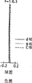
In the aberration of representing with spherical aberration (axial chromatic aberration) figure, solid line and two kinds of dotted lines are represented about d the spherical aberration of g and c line respectively.
In lateral chromatic aberration figure, two kinds of dotted lines are represented the magnification about g and c line respectively; But the d line is as the baseline consistent with ordinate.
In astigmatism figure, S represents sagitta of arc picture, and M represents the meridian picture.
Form, FNO. represent the f number, f represents the focal length of whole zoom-lens system, W represent half angle of view (°), fB represents back focal length (equal along optical axis from the 3rd positive lens groups 30 by the air thickness of picture side's side surface to the picture plane of imaging device), and r represents radius-of-curvature, and d represents the distance between lens element thickness or the lens element, Nd represents the refractive index of d line, and v represents Abbe number.
Except that above-mentioned, be defined as follows about the aspheric surface of symmetrical:
x=cy
2/(1+[1-{1+K}c
2y
2]
1/2)+A4y
4+A6y
6+A8y
8+A10y
10…
Wherein:
C represents the curvature (1/r) on aspheric surface summit;
Y represents the distance with optical axis;
K represents circular cone (conic) coefficient; With
A4 represents the quadravalence asphericity coefficient;
A6 represents the 6th rank asphericity coefficient;
A8 represents the 8th rank asphericity coefficient; With
A10 represents the tenth rank asphericity coefficient.
[embodiment 1]
Fig. 1 is the lens layout according to the zoom-lens system of first embodiment of the invention.Fig. 2 A-2D represents the aberration that lens layout shown in Figure 1 produces at short focal length extremity.Fig. 3 A-3D represents the aberration that lens layout shown in Figure 1 produces in the middle focal length position.Fig. 4 A-4D represents the aberration that lens layout shown in Figure 1 produces at long focal length extremity.The numeric data of form 1 expression first embodiment.
First negative lens group 10 comprises according to first negative lens element and second positive element from the object space order.The object space side surface of second positive element and picture side's side surface form aspheric surface, and each aspheric surface is about symmetrical.
Second positive lens groups 20 comprises the 3rd positive element, the 4th negative lens element and the 5th positive element, and all these elements glue together mutually according to the order from object space.Picture side's side surface of the object space side surface of the 3rd positive element and the 5th positive element forms aspheric surface, and each aspheric surface is about symmetrical.
The 3rd positive lens groups 20 comprises the positive crescent lens element (the 6th positive element) with the convex surface that faces image.The object space side surface of positive crescent lens element and picture side's side surface form aspheric surface, and each aspheric surface is about symmetrical.
The cover glass that is placed on the imaging device front is arranged on the back (on image-side) of the 3rd positive lens groups 30.
In second positive lens groups, 20 the place aheads (surface NO .5), aperture S is configured to 0.20.
Table 1
F=1:3.6-4.6-6.3
f=4.40-7.60-13.00
W=35.4-20.7-12.4
F
B=2.50-2.50-2.50
Surface sequence number r d Nd v
1 371.737 0.50 1.88300 40.8
2 4.285 0.93 - -
3
* 7.896 1.00 1.84666 23.8
4
* 36.355 8.80-3.54-0.54 - -
5
* 3.577 1.17 1.87408 41.3
6 250.000 1.00 1.69287 29.8
7 1.899 1.55 1.58636 60.9
8
* 6.428 3.25-5.57-9.48 - -
9
* -6.904 0.90 1.65128 38.3
10
* -4.562 1.00 - -
11 ∞ 0.50 1.51633 64.1
12 ∞ - - -
Symbol * represents about the rotational symmetric aspheric surface of optical axis.
Aspherical surface data (asphericity coefficient of not representing is zero (0.00)):
Surface sequence number K A4 A6 A8
3 0.00 -0.37957×10
-3 0.72870×10
-4?-0.59022×10
-5
4 0.00 -0.11275×10
-2 0.55760×10
-4?-0.88593×10
-5
5 0.00 -0.25165×10
-3?-0.68257×10
-4
8 0.00 0.10802×10
-1 0.15863×10
-2 0.20000×10
-4
9 0.00 -0.53057×10
-2 0.73506×10
-3?-0.44593×10
-5
10 0.00 -0.28029×10
-2 0.38430×10
-3?-0.25000×10
-4
[embodiment 2]
Fig. 5 is the lens layout according to the zoom-lens system of second embodiment of the invention.Fig. 6 A-6D represents the aberration that lens layout shown in Figure 5 produces at short burnt end.Fig. 7 A-7D represents the aberration that lens layout shown in Figure 5 produces in the middle focal length position.Fig. 8 A-8D represents the aberration that lens layout shown in Figure 5 produces at long focal length extremity.The numeric data of form 2 expressions second embodiment.
The basic lens layout of second embodiment is basically the same as those in the first embodiment, except picture side's side surface of first negative lens element of first negative lens group 10 forms the aspheric surface.
In second positive lens 20 the place aheads (surface NO .5), aperture S is configured to 0.20.
[form 2]
F=1:3.5-4.6-6.3
f=4.40-7.60-13.00
W=35.3-20.9-12.6
F
B=2.60-2.60-2.60
Surface sequence number r d Nd v
1 20.838 0.50 1.88300 40.8
2
* 3.633 1.01 - -
3
* 5.973 0.96 1.84666 23.8
4
* 11.973 8.15-3.38-0.66 - -
5
* 3.548 1.16 1.83481 42.7
6 125.000 1.00 1.68740 29.6
7 1.999 1.80 1.59884 54.6
8
* 7.987 2.99-5.31-9.22 - -
9
* -5.409 0.90 1.63854 55.4
10
* -4.100 1.00 - -
11 ∞ 0.50 1.51633 64.1
12 ∞ - - -
Symbol * represents about the rotational symmetric aspheric surface of optical axis.
Aspherical surface data (asphericity coefficient of not representing is zero (0.00)):
Surface sequence number K A4 A6 A8
2 0.00 -0.63085×10
-4 0.85225×10
-5
3 0.00 -0.77823×10
-3 0.62326×10
-4?-0.12357×10
-4
4 0.00 -0.16913×10
-2 0.21552×10
-4?-0.16513×10
-4
5 0.00 -0.38972×10
-3?-0.89671×10
-4
8 0.00 0.10781×10
-1 0.16503×10
-2 0.20000×10
-4
9 0.00 -0.75191×10
-2 0.66822×10
-3 0.44593×10
-5
10 0.00 -0.42498×10
-2 0.24916×10
-3 0.25000×10
-4
[embodiment 3]
Fig. 9 is the lens layout according to the zoom-lens system of third embodiment of the invention.Figure 10 A-10D represents the aberration that lens layout shown in Figure 9 produces at short focal length extremity.Figure 11 A-11D represents the aberration that lens layout shown in Figure 9 produces in the middle focal length position.Figure 12 A-12D represents the aberration that lens layout shown in Figure 9 produces at long focal length extremity.The numeric data of form 3 expressions the 3rd embodiment.
The basic lens layout of the 3rd embodiment is identical with second embodiment's.
In second lens combination, 20 the place aheads (surface NO .5), aperture S is set to 0.20.
[form 3]
F=1:3.6-4.6-6.3
f=4.40-7.60-13.00
W=35.2-20.5-12.3
FB=2.20-2.20-2.20
Surface sequence number r d Nd v
1 -306.390 0.50 1.88300 40.8
2
* 4.300 1.06 - -
3
* 7.633 0.97 1.84666 23.8
4
* 35.433 9.16-3.66-0.53 - -
5
* 3.455 1.19 1.88300 40.8
6 90.000 1.01 1.71677 28.1
7 1.688 1.44 1.58309 47.2
8
* 6.659 3.62-5.94-9.85 - -
9
* -8.868 0.97 1.67859 30.5
10
* -5.275 1.00 - -
11 ∞ 0.50 1.51633 64.1
12 ∞ - - -
Symbol * represents about the rotational symmetric aspheric surface of optical axis.
Aspherical surface data (asphericity coefficient of not representing is zero (0.00)):
Surface sequence number K A4 A6 A8
2 0.00 -0.14624×10
-2?0.38977×10
-4
3 0.00 -0.19699×10
-2?0.55384×10
-4-0.38703×10
-5
4 0.00 -0.17729×10
-2?0.22016×10
-4-0.62418×10
-5
5 0.00 -0.35502×10
-3-0.63574×10
-4
8 0.00 0.10216×10
-1?0.84465×10
-3?0.20000×10
-4
9 0.00 -0.32206×10
-2?0.52473×10
-3?0.44593×10
-5
10 0.00 -0.77385×10
-3?0.19518×10
-3?0.25000×10
-4
The numerical value of every kind of condition of each embodiment as shown in Table 4.
[form 4]
Embodiment 1 embodiment 2 embodiment 3
Condition (1) 1.43 1.37 1.47
Condition (2) 1.06 1.01 1.09
Condition (3)-1.59-1.48-1.82
Condition (4) 1.08 1.10 1.26
Condition (5) 2.17 2.00 2.21
Condition (6) 0.35 0.29 0.37
Condition (7) 0.85 0.90 0.83
Condition (8) 0.06 0.04 0.08
Condition (9) 21.3 19.1 15.9
Condition (10) 15.2 15.6 14.8
Condition (11) 8.25 8.78 7.67
Condition (12) 250.0 120.0 90.0
Condition (13) 2.95 2.95 2.95
Can understand each of first to the 3rd embodiment (1)-(13) that all satisfy condition from form 4.And as understandable from aberration diagram, various aberrations are fully proofreaied and correct.
According to top description, can obtain to have the microminiature zoom-lens system of following feature: the lens element of smaller amounts;
Zoom is 2-3;
Reach the higher optical property that is suitable for the higher pixelation of imaging device.
Can carry out various variations in the specific embodiments of the invention described here, this variation is in the spirit and scope of invention claim.Should illustrate, be illustrative at these all themes that comprise, and do not limit the scope of the invention.