Embodiment
Below with reference to the accompanying drawings an embodiment of the invention are described.
Fig. 1 is the structural drawing of the sensor network system representing the first embodiment of the present invention.
(system architecture summary)
Sensor node WSN (wireless sensor node), MSN (wireless movable sensor node) be arranged on regulation position on or be arranged on article or by people and carry, collect about the information of environment or about the information of article of having installed this sensor, this information is sent to the node of base station BS T-1 ~ n.Sensor node is made up of wireless sensor node WSN, MSN of being wirelessly connected on base station BS T-1 ~ n and the wired sensor nodes FSN be connected in a wired fashion on network N WK-n.Further, the general name list of wireless sensor node WSN, MSN and wired sensor nodes FSN is called sensor node.
Be fixed the wireless sensor node WSN arranged, and such as, by the situation around the cycle sensor ground sensing of carrying, and sends heat transfer agent to the base station BS T that presets.Wireless movable sensor node MSN is using the hand-held walking of people, vehicle-mounted etc. premised on moveable mode, information is sent to nearest base station BS T.Further, when indicate wireless sensor node entirety (general name) time be used as WSN or MSN, when indicate one by one wireless sensor node time, be accompanied with subscript like this to represent with being similar to WSN-1 ~ n or MSN-1 ~ n.Below other textural element equally represent general name time standby not subscripting represent, representing that time standby is one by one accompanied with subscript (-1 ~ n) and represents.
In each base station BS T-1 ~ n, connect 1 or multiple wireless sensor node WSN, MSN, each base station BS T-1 ~ n is connected on the separate data processing server DDS-1 ~ n of collection from the data of each sensor node via network N WK-2 ~ n.Further, network N WK-2 ~ n is for connecting base station BS T and separate data processing server (distributing server) DDS.Separate data processing server DDS changes its number connected according to the large I of system scale.
Each separate data processing server DDS-1 ~ n has the disk set DSK and not shown CPU and storer that store wireless and data detected by wired sensor nodes (being called sensor node to place an order) etc., the program put rules into practice, collect the determination data from sensor node as described later, according to prespecified condition, carry out data storage, data mart modeling so that carry out notifying to LIST SERVER (management server) DRS or other server via network N WK-1, the action of data retransmission etc.Further, network N WK-1 is made up of LAN or the Internet etc.
Here, the numeric data of the inherent data ID of identification sensor node or categories of sensors etc. is mainly given from the data of sensor node collection, represent the change on corresponding time series, but its former state does not become the form of user (users of the user terminal UST etc.) easy understand of the output using sensor node.So, according to the definition preset on LIST SERVER DRS, after the output data of sensor node being transformed into the intelligible Real-world model of user (people, thing, state etc.), be prompted to user.
Further, separate data processing server DDS-1 ~ n collect data to as if belong to the network N WK-2 ~ n being connected to own base stations base station BS T sensor node or from other base station BSs T move come wireless sensor node MSN.In addition, wired sensor nodes FSN can be connected on separate data processing server DDS-1 ~ n.Certainly, also wired sensor nodes FSN can be connected to base station BS T, and base station BS T and managing wireless sensing device node similarly manage wired sensor nodes FSN.
The LIST SERVER DRS managing the Real-world model associated with the heat transfer agent of sending from separate data processing server DDS is connected with in network N WK-1, use the user terminal UST of the information of this LIST SERVER DRS, carry out LIST SERVER DRS, separate data processing server DDS and base station BS T, the setting of sensor node and the office terminal ADT of management.Further, office terminal also can prepare the service manager for the sensor management person of management of sensor node, the service of management of sensor network respectively.
LIST SERVER DRS has not shown CPU, storer and memory storage, the program put rules into practice, and manages the object be associated with useful information as described later.
Namely, when user is by user terminal UST Real-world model request access, LIST SERVER DRS access has the separate data processing server DDS-1 ~ n of this determination data to real world, obtain this determination data, if necessary this sensing data is transformed to the form of user's easy understand, and shows on user terminal UST.
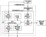
Fig. 2 is the functional-block diagram of the sensor network shown in Fig. 1.Here, in order to make explanation concise and to the point, only represent the structure of separate data processing server DDS-1 in the separate data processing server DDS-1 ~ n of Fig. 1, in addition, only represent the structure of base station BS T-1 in the base station BS T-1 ~ n be connected on separate data processing server DDS-1.Other separate data processing servers DDS, base station BS T are also same structures.
Below, each several part detailed content is described.
(base station BS T)
The base station BS T-1 collecting data from wireless sensor node WSN, MSN or wired sensor nodes FSN (hereinafter referred to as sensor node) has command control unit CMC-B, sensor node administrative unit SNM and event monitor unit EVM.Further, sensor node adds the data ID preset, and sends determination data.
On command control unit CMC-B, enterprising line command transmission and reception between the command control unit CMC-D of separate data processing server DDS-1 described later.The such as corresponding order from separate data processing server DDS-1, performs the setting of the parameter of base station BS T-1, sends the state of base station BS T-1 to separate data processing server DDS-1.Or, perform the setting of the parameter of the sensor node of base station BS T-1 management, send the state of sensor node to separate data processing server DDS-1.
Sensor node administrative unit SNM keeps the management information (duty, afterpower etc.) of the sensor node of self-management.And, when there being the inquiry about sensor node from separate data processing server DDS-1, replace each sensor node to notify management information.Entrust base station BS T to carry out due to sensor node and manage the process be associated, so self processing load can be reduced, unnecessary power consumption can be suppressed.
In addition, the management information of sensor node administrative unit SNM more new sensor node when event monitor unit EVM is tested with abnormal, notifies about the information having abnormal sensor node to separate data processing server DDS-1.And so-called sensor node is extremely when without response from sensor node, or under the power of sensor node is less than or equal to the situations such as the threshold value preset, represent function stop or until the state that stops of sensor node.
In addition, sensor node administrative unit SNM is when receiving the order to sensor node (changing the parameter etc. exporting timing) from command control unit CMC-D, send this order to sensor node to set, then from after sensor node have received and represents and set the notice that finishes, the more management information of new sensor node.Further, the output timing indicator example of sensor node is if wireless sensor node WSN is periodically to the period of base station BS T-1 transmission data.
Base station BS T manages wireless sensor node WSN, MSN of the subordinate preset and wired sensor nodes FSN, and sends the data of each sensor node mensuration to separate data processing server DDS.
(separate data processing server DDS)
Separate data processing server DDS-1 has disk set DSK, command control unit CMC-D, event-action control module EAC and the database control unit DBC as described later of stored data base DB.
Command control unit CMC-D communicates with base station BS T and aftermentioned LIST SERVER DRS, carries out the transmission and reception of order etc.
Event-action control module EAC receives the determination data from sensor node from base station BS T at every turn, all obtain the ID corresponding with determination data, i.e. data ID, from table described later (the event table ETB of Figure 10), read in the event corresponding with data ID rule occurs, determine whether and the event corresponding with the value of determination data occurs.And then, event-action control module EAC performs the action that the generation notice of the event corresponding to data ID is corresponding.Further, when only having 1 sensor in sensor node, the ID of the sensor node of identification sensor node will can be used for as data ID.
In addition, in present embodiment, so-called event represents the condition preset about determination data (or process data).In addition, so-called event represents that determination data meets the situation of defined terms.
And, comprising the rule of each data ID according to being preset by user etc. as action implementation content, determination data being transformed to process data, by database control unit DBC to database D B storing measurement data and process data, carry out the process that notifies etc. in addition to LIST SERVER DRS or other servers.
In the present embodiment, as shown in Figure 1, by being configured in certain the several multiple separate data processing server DDS geographically gathered in these to multiple base station BS T, the information dispersibled from multiple sensor node is gone forward side by side row relax.Such as, in Office etc., a separate data processing server DDS can be designed to each floor, also in factory etc., a separate data processing server DDS can be designed in each buildings.
The disk set DSK of separate data processing server DDS-1 stores using the determination data of sensor node WSN, MSN, FSN of receiving from base station BS T and the process data obtained after machined these determination datas with about the device data of base station BS T, wireless sensor node WSN, MSN and wired sensor nodes FSN as database D B.
And the determination data of the output as the sensor node sent from event action control unit EAC is stored in database D B by the database control unit DBC of data processing server DDS-1.In addition, be stored into by data processing determination data or with the process data that other data fusion obtain in database D B if necessary.Further, upgrade at any time with from the request of manager terminal ADT etc. is corresponding about device data.
(LIST SERVER DRS)
The LIST SERVER DRS managing multiple separate data processing server DDS comprises and controlling from the control dialog unit SES of the communication of the user terminal UST connected via network N WK-1 or manager terminal ADT and model management unit MMG, model table MTB as described later, device management unit NMG, action control unit ACC and search engine SER.
Model management unit MMG by the determination data that sets the model (object) of the real world of user's easy understand and separate data processing server DDS collect from sensor node in Real-world model table MTB or and the Real-world model list MDL of corresponding relation of process data manage.And then be exactly, Real-world model table MTB using intelligible for user meaning information as object, the ID of the determination data (or process data) of sensor node is corresponding with object with whereabouts (storage) in the future, is looked like in addition in addition explain that the determination data of list ATL sensor node in future is transformed to the intelligible meaning information of user by attribute described later.
LIST SERVER DRS also manages the positional information (links of URL etc.) that the determination data that is equivalent to Real-world model or process data exist place.And then user, by specifying Real-world model, may have access to up-to-date mensuration information or the record data place catalogue in the past of the sensor node of moment change.For from the determination data of sensor node and process data along with the time increases, even if time lapse, Real-world model information size does not also change, and just content changes.Detailed content about this Real-world model describes below.
Further, Real-world model table MTB is stored in the memory storage (diagram is omitted) that LIST SERVER DRS specifies etc.
The action control unit ACC of LIST SERVER DRS communicates with the event-action control module EAC of separate data processing server DDS or command control unit CMC-D, accepts the setting request of the event-action of user terminal UST or manager terminal ADT.Further, analyze the content of event or the action received, the function set between the LIST SERVER DRS of corresponding analysis result and separate data processing server DDS-1 ~ n is shared.Further, an action or event are not only a separate data processing server DDS, also have the situation relevant with multiple separate data processing server DDS-1 ~ n.
Search engine SER, according to the retrieval request of the object received control dialog unit SES, with reference to Real-world model table MTB, retrieves the database D B of separate data processing server DDS.
Further, if retrieval request is inquiry, then performs and convert according to the correspondence of the database D B of query contents and the SQL (Structured Query Language) of inquiry, then perform retrieval.And there is the database D B becoming searching object to cross over the situation of multiple separate data processing server DDS.
And, be corresponding with " latest data obtains (taking out a little/stream) " as this inquiry.And " latest data obtains (stream) " is corresponding by the setting of the action of action control unit ACC.And then can set corresponding data retransmission on the event-action control module EAC of this separate data processing server DDS to this setting of action on the server of usually wishing or terminal.
Then, device management unit NMG unified management is connected to separate data processing server DDS, the base station BS T be connected on separate data processing server DDS, the sensor node be connected on base station BS T that network N WK-1 forms sensor network.
On device management unit NMG, provide separate data processing server DDS, base station BS T to manager terminal ADT etc., relate to the registration of sensor node, the interface of retrieval, respectively the state of management devices, the state of sensor node.
Device management unit NMG can to separate data processing server DDS, base station BS T, sensor node granting order, by the resource of this order management sensor network.And, sensor node is via the command control unit CMC-B becoming upper base station BS T, take orders from device management unit NMG, base station BS T, via the command control unit CMC-D of upper separate data processing server DDS, takes orders from device management unit NMG.
Further, as the order that device management unit NMG provides via command control unit CMC-D, such as reset, setting parameter, data deletion, data retransmission, the setting of sizing Event/Action Model etc. are had.
(example of sensor node)
Then, an example of sensor node is represented in figs. 3-5.
Fig. 3 is the block scheme of the example representing wireless sensor node WSN.Wireless sensor node WSN is the sensor SSR being changed (low temperature/high temperature, low pressure/high pressure etc.) by the quantity of state (temperature, pressure, position etc.) or quantity of state that measure determination object, controller CNT and the base station BS T of control sensor SSR carry out the wireless processing unit WPR communicated, and the power supply POW powered to each piece of SSR, CNT, WPR and the antenna ANT carrying out transmission and reception is formed.
Controller CNT reads in the determination data of sensor SSR with the predetermined cycle, adds the data ID preset, be then forwarded to wireless processing unit WPR to this determination data.Determination data also has the temporal information of distributing and carrying out sensing as the situation of time tag.Wireless processing unit WPR sends the data sent from controller CNT to base station BS T.
In addition, wireless processing unit WPR sends the order etc. received from base station BS T to controller CNT, controller CNT resolves the order that have received, and carries out the process (such as setting is changed) specified.In addition, the information of power supply POW afterpower (or charge volume) is sent to base station BS T via wireless processing unit WPR by controller CNT.Further, the afterpower (or charge volume) of controller CNT self monitor power supply POW, when afterpower is lower than the threshold value preset, can to the alarm of base station BS T transmitted power deficiency.
On wireless processing unit WPR, in order to measure for a long time by limited electric power, as shown in Figure 4, intermittently action, reduces power consumption.In figure, in dormant state SLP, the driving of controller CNT stop sensor SSR, switches to operating state with the cycle specified from dormant state, and driving sensor SSR sends determination data.
Further, what represent in figure 3 is the example that a wireless sensor node WSN has 1 sensor SSR, but also can configure multiple sensor SSR.Or can replace sensor SSR, design stores the storer of intrinsic identifier ID, also wireless sensor node WSN can be used as label.
In addition, on Fig. 3, Fig. 4, voltage POW uses the situation of battery or has the structure of the independent power generation such as solar cell or vibrating power-generation structure.In addition, wireless movable sensor node MSN also can be the structure same with Fig. 3, Fig. 4.
Fig. 5 is the details drawing of the example representing the sensor node be connected on the separate data processing server DDS-1 shown in above-mentioned Fig. 1, Fig. 2.
In the present embodiment, the example Office and A meeting room, B being devised to sensor node is illustrated.
In Office, be provided with base station BS T-0, the chair of Office is configured with the wireless sensor node WSN-0 as sensor SSR with pressure-sensitive (pressure) switch.Wireless sensor node WSN-0 is set to the mode communicated with base station BS T-0.
Base station BS T-1 is set in A meeting room, the chair of A meeting room is configured with wireless sensor node WSN-3 ~ 10 as sensor SSR with pressure sensitive switch.In addition, be provided with the wired sensor nodes FSN-1 with temperature sensor inside A meeting room, and be connected on base station BS T-1.Each wireless sensor node WSN-3 ~ 10 and wired sensor nodes FSN-1 are set as and the mode that base station BS T-1 communicates.
Equally, base station BS T-2 is provided with in meeting room B, the chair of meeting room B is provided with and as sensor SSR, there are wireless sensor node WSN-11 ~ 18 of pressure sensitive switch and have the wired sensor nodes FSN-2 of temperature sensor, and be connected on base station BS T-2.
The wireless sensor node MSN-1 of double chest card is worn to the staff of these A meeting rooms of use, B.Wireless sensor node MSN-1 measures the temperature sensor SSR-1 of staff's body temperature (or environment temperature) as having, and the chest card of the label TG-1 storing the intrinsic identifier of staff (staff ID) is configured.Wireless sensor node MSN-1 can send staff ID and the temperature as determination data to base station BS T-0,1 or 2.
(movement concept of sensor network)
Then, use Fig. 6 ~ Fig. 8 that the summary of the action of the sensor network represented on above-mentioned Fig. 1 ~ Fig. 5 is described.
Fig. 6 is the block scheme associated representing the data that the object as the concrete form of Real-world model measures with sensor node, is to represent to measure start time, and Fig. 7 represents the state of state after the stipulated time from Fig. 6.
In figure 6, LIST SERVER DRS generates next target in advance as Real-world model, is defined into the Real-world model list MDL of Real-world model table MTB.Here, the situation as using Office or the A meeting room of Fig. 5, staff's Suzuki of B meeting room is illustrated, using the article that the wireless sensor node MSN-1 shown in Fig. 6 wears as this personage.
As shown in the sensor information table STB of Figure 12, resemble and in the separate data processing server DDS specified by address data memory, define sensor information table the determination data (ex. temperature) of each sensor node MSN or positional information to be stored into like this.Here, the id information that the positional information of sensor node MSN can be used as the base station BS T of detecting sensor node M SN obtains.
And, the object (OBJ-1) defining so-called Suzuki position in the Real-world model list MDL of Real-world model table MTB has the situation of data entity on the ground at the storage purpose of so-called determination data 1 (LINK-1), and manages the corresponding relation of the memory location of Real-world model and real data.
That is, in Real-world model list MDL, the object of so-called Suzuki position (OBJ-1) is associating with the memory location of the separate data processing server DDS of corresponding determination data 1 (LINK-1).On Fig. 6, Fig. 7, in the disk set DSK1 of separate data processing server DDS, store the positional information (being such as defined as " being connected to which base station BS T ") from the wireless sensor node MSN-1 representing Suzuki position.
From user terminal UST, the value of Suzuki position (OBJ-1) looks like and is present in the Real-world model table MTB of LIST SERVER DRS, but real data is not be stored on LIST SERVER DRS, but be stored in the disk set DSK1 of the separate data processing server DDS-1 preset.
The information of taking a seat obtained from the pressure sensitive switch be arranged on Office chair (WSN-0) be stored in determination data 2 (LINK-2), in Real-world model table MTB, definition is referred to as Suzuki and takes a seat (OBJ-2) such object.And then, define the separate data processing server DDS corresponding with determination data 2 and memory location.On Fig. 6, Fig. 7, the information of taking a seat from MSN-1 and wireless sensor node WSN is stored in the disk set DSK2 of separate data processing server DDS-1.
The temperature that the temperature sensor SSR-1 of wireless sensor node MSN-1 measures be stored in determination data 3 (LINK-3), in Real-world model table MTB, definition is referred to as the object of Suzuki body temperature (OBJ-3).And then, define the separate data processing server DDS corresponding with determination data 3 and memory location.Point the temperature stored from MSN-1 is being spread in the disk set DSK3 of data processing server DDS-1 in Fig. 6, Fig. 7.
Staff's name of trying to achieve in the information of the wireless sensor node MSN connected by the base station BS T-1 from A meeting room is stored in determination data 4 (LINK-4), and in Real-world model table MTB, definition is referred to as the object of A meeting room member (OBJ-4).When not using pressure sensitive switch (WSN-3 ~ 10), the number of A meeting room can be tried to achieve by the number of the wireless sensor node MSN detected in the base station BS T-1 within certain unit interval in A meeting room.And then, define the separate data processing server DDS corresponding with determination data 4 and memory location.In Fig. 6, Fig. 7, in the disk set DSK4 of separate data processing server DDS, store the personal information of the wireless sensor node MSN from each staff.
Be stored in determination data 5 (LINK-5) by the number of trying to achieve from the pressure sensitive switch (WSN-3 ~ 10) of A meeting room, in Real-world model table MTB, definition is referred to as the object of A meeting room number (OBJ-5).And then, define the separate data processing server DDS corresponding with determination data 5 and memory location.In Fig. 6, Fig. 7, in the disk set DSK5 of separate data processing server DDS-1, store the information of taking a seat of wireless sensor node MSN3 ~ 10.
Be stored in determination data 6 (LINK-6) by the temperature that the wired sensor nodes FSN-1 from A meeting room measures, in Real-world model table MTB, definition is referred to as the object of A meeting room temperature (OBJ-6).And then, define the separate data processing server DDS corresponding with determination data 6 and memory location.In Fig. 6, Fig. 7, in the disk set DSK6 of separate data processing server DDS-1, store the temperature from FSN-1.
Namely, the each object OBJ defined in Real-world model table MTB stores the storage destination (LINK) corresponding with determination data, look like destination data from user terminal UST to be present in LIST SERVER DRS, but actual data are stored on separate data processing server DDS.
And, set the memory location of determination data that sensor node measures or the process data that obtains of mathematic(al) manipulation determination data etc., the spendable data of user in information storage destination LINK.Each separate data processing server DDS carries out collecting the determination data from sensor node, and then, if set event-action as described later, then determination data is processed etc., and it can be used as process data to be stored in the separate data processing server DDS of regulation to go.
Separate data processing server DDS carries out the data of the sensor node collected and process from reality, and LIST SERVER DRS manages the storage destination of Real-world model and information and the definition etc. of sensor node.
Thus, the user of user terminal UST does not need to know sensor node whereabouts, by searching object OBJ, just can obtain the desired data corresponding with the measured value of sensor node (or process data).
And, because LIST SERVER DRS manages the storage destination (link destination) of each object OBJ, the stores/processes that actual data are disperseed by separate data processing server DDS, even if so the number of sensor node becomes huge, also can prevent the load of sensing data process from becoming excessive.In addition, multiple sensor node can be used, while suppress the traffic of the network N WK-1 connecting LIST SERVER DRS and separate data processing server DDS and user terminal UST to become excessive.
From on Fig. 7 after the stipulated time of Fig. 6 state, to disk set DSK1 ~ 6 write of separate data processing server DDS-1 from the determination data of the reality of sensor node, as time goes by, data volume is corresponding increase also.
On the other hand, with be set at LIST SERVER DRS Real-world model table MTB model list MDL in storage destination LINK-1 ~ 6 corresponding to object OBJ-1 ~ 6, even if time lapse, quantity of information did not also change, and the information content that just storage destination LINK-1 ~ 6 indicate changes.
Namely, the temporal relation of data volume of the determination data 1 ~ 6 that the quantity of information of object OBJ-1 ~ 6 of LIST SERVER DRS management and separate data processing server DDS-1 manage as shown in fig. 8, time data volume for object is certain, determination data increases in time and increases.
Such as, 1 base station BS T is connected to hundreds of sensor nodes, a separate data processing server DDS is connected to several base station BS T, when a LIST SERVER DRS being connected to dozens of separate data processing server DDS, the sum of sensor node just becomes thousands of and even tens thousand of.Suppose that each each minute of sensor node sends a secondary data in turn, hundreds of determination data to thousands of left and right so per second is sent on separate data processing server DDS, determine whether that event occurs, when there occurs event, produced the process of notice or data mart modeling etc. by the action specified.If these process are want with the server realization of or minority, then server self load, become very big for the load of the network be connected with server.And then, about the data that have collected and manufactured data, owing to accessing from user terminal UST, and owing to providing data to user terminal UST, so server load, network load become large further.
So, with accepting the interview from user terminal UST and the LIST SERVER DRS of storage destination of the information of management of sensor node, and the multiple base station BS T of management and collect from the sensor node distributed by base station BS T, the separate data processing server DDS of process data carries out process and shares.
From the information of sensor node, by disperseing with multiple separate data processing server DDS and collect, storage or the processing of data is carried out respectively with each separate data processing server DDS, dispersible collection and the processing process of the data of multiple sensor node, prevent load in specific server from concentrating.
On the other hand, LIST SERVER DRS intensively (unitary ground) manages the storage destination of the information obtained from the determination data of sensor node, provides the corresponding relation of object and storage destination LINK to user terminal UST.Even if user does not know the physical location etc. of sensor node, if carry out the inquiry about object object to LIST SERVER DRS, then can obtain useful information from the memory location of data.Namely by the storage destination by LIST SERVER DRS integrated management information, regardless of the residing part of sensor node, if user terminal UST conducts interviews to LIST SERVER DRS, the determination data about object sensor node or process data just can be obtained.
And LIST SERVER DRS looks like in addition according to attribute and explains that the data obtained from separate data processing server DDS are transformed into the understandable information of user (meaning information) by list ATL, is supplied to user terminal UST.
In addition, due to be stored on LIST SERVER DRS to as if correspondence constructed by the structure of system be set/change, instead of the determination data that image sensor nodal test goes out is equally time dependent, so the part of the management object concentrated is not by the impact of the load change of time dependent determination data.Thus, owing to inhibit the data of directly switching sensors node between separate data processing server DDS, so the load of the network N WK-1 be connected on LIST SERVER DRS can be suppressed to become excessive.
And, on Fig. 6, Fig. 7, the situation being connected to disk set DSK is represented respectively to each separate data processing server DDS, but a separate data processing server DDS can be designed as with figure 5, multiple disk set DSK can be designed here, also can divide into groups to connect disk set DSK in multiple separate data processing server DDS.
(relation of determination data and event)
Then, in Fig. 9, Figure 10, represent the relation of the determination data collected by separate data processing server DDS and the event-action according to determination data.
In fig .9, the event-action control module EAC of separate data processing server DDS has the event table ETB be mapped with event by the determination data collected from base station BS T.
Event table ETB as shown on Figure 10, by the data ID of giving to determination data (data ID of ID and Figure 14 of corresponding Figure 12), about determination data as event generation Rule of judgment EVT, determine that whether the data be stored on database D B store DHL and form a record by determination data.
Such as, in figure, data ID is the determination data of " XXX ", and when this value is larger than A1, notice LIST SERVER DRS event occurs.Further, data ID is that the determination data of " XXX " arrives each data, all sets in the mode being written to disk DSK.The storage carried out to disk DSK carries out setting according to setting in the action hurdle of event table ETB.
On separate data processing server DDS, first accepted the determination data sent from base station BS T by sensing data ID extraction unit, then extract the data ID as the ID giving determination data.In addition, determination data is sent to latest data storer LDM by sensing data ID extraction unit IDE.
The data ID be extracted is sent to fact retrieval unit EVS, retrieval event table ETB, if the record having data ID consistent, then sends event content EVT and the determination data of this record to event generation identifying unit EVM.
On event generation identifying unit EVM, the value of comparative measurements data and event content EVT, if do not satisfied condition, inform to LIST SERVER DRS from network processing unit NWP by event by network N WK-1.In addition, the request that data are stored DHL by event generation identifying unit EVM sends to latest data storer.
DB control module DBC, the data for event table ETB store the data that DHL becomes YES, accept data, be written in disk set DSK from latest data storer LDM.
Separate data processing server DDS, when network processing unit NWP to be have received the refer request of determination data by LIST SERVER DRS, sends this request of access to data access receiving unit DAR.
On data access receiving unit DAR, if request of access is up-to-date data, reads in the determination data corresponding with the data ID that request of access comprises from latest data storer LDM, return network processing unit NWP.Or, if request of access is data in the past, reads in the determination data corresponding with the data ID that request of access comprises from disk set DSK, return network processing unit NWP.
Like this, on separate data processing server DDS, in the data of the sensor node collected from base station, latest data storer LDM keeps latest data, and then, be only recorded in being envisioned as in disk set DSK with reference to the data being necessity below.In addition, data when also can only occur event carry out setting data be recorded on disk set DSK.In this case, the disk use amount caused by data that (observation interval) can be prevented periodically to collect increases.By above method, an available separate data processing server DDS manages multiple base station BS T (that is, multiple sensor node).
(device management unit NMG's and model management unit MMG is detailed)
(device management unit NMG)
Figure 11 represents device management unit NMG, the model management unit MMG of the LIST SERVER DRS shown in Fig. 2 and the detailed of Real-world model table MTB.
First, the device management unit NMG of LIST SERVER DRS has the sensor information table STB of management of sensor node, the search interface for the enrollment interface of registration on sensor information table STB/change sensor node, the content of retrieval sensor information table STB.Further, here, by sensor management person terminal ADT-A management of sensor information table STB.
Sensor information table STB, as shown in Figure 12, by the data ID allocated in advance the sensing data source of each sensor node or each sensor in a record, represent the categories of sensors of the kind of sensor node, represent the meaning of the determination object of sensor node, the content of the variable that sensor node measures, represent the setting place being provided with the position (or object) of sensor node, represent the observation interval of sensor node from the cycle of determination object detection assay value, represent that the data storage destination of the storage destination (memory location on separate data processing server DDS-1 ~ n) of the data measured is formed, using data ID as index management.
Such as, as the label TG-1 of the wireless sensor node MSN-1 that the chest card shown in Fig. 5 is formed, the data ID illustrating sensor node is assigned to 01, determination object is the place (position) of wireless sensor node MSN-1, determination period is every 30 seconds, and determination data is stored in separate data processing server DDS-1.Equally, as the sensor SSR-1 that chest card configures in formed wireless sensor node MSN-1, represent that data ID is assigned to O2, determination object is environment temperature, determination period is every 60 seconds, and determination data is stored in separate data processing server DDS-2.
This sensor information table STB is set by the sensor manager terminal ADT-A, sensor management person or service manager by referring to sensor information table STB, the function of known road sensor node and the storage destination of position and determination data.
In addition, when the cycle of sensor node determination data is not certain, the seat occupancy sensor of data ID=03 is as shown in figure 12 the same, by observation interval is set to " event ", no matter the cycle is how, if sensor detected specific state just by this state notifying to separate data processing server DDS.
(model management unit MMG)
Then, the model management unit MMG shown in Figure 11 and Real-world model table MTB is described.
The Real-world model table MTB that model management unit MMG manages be by for explain the determination data of sensor node be the attribute with what kind of meaning look like in addition explain list ATL, represent the Real-world model list MDL of corresponding relation between the model name of object OBJ-1 ~ n shown in Fig. 6 and the memory location of the information of reality, the models coupling list MBL of association that represents between object OBJ-1 ~ n forms.
And, model management unit MMG is in order to manage each list of these Real-world model tables MTB, have management attribute look like in addition explain the attribute of list ATL look like in addition explain list management unit ATM, management Real-world model list MDL Real-world model list management unit MLM, administrative model in conjunction with the models coupling list management unit MBM of list MBL, each administrative unit have respectively the registration/change for carrying out list enrollment interface, for carrying out the search interface of each list retrieval.
Further, here, Real-world model list MTB is by using the service manager of service manager terminal ADT-B to manage.Further, on Figure 11, sensor management person terminal and service manager terminal, can use an office terminal ADT as shown in Figure 1.
In addition, search interface from the desired list searching object OBJ of user terminal UST via each list of sensor network is used.
First, attribute looks like in addition and explains that the attribute of list management unit atm management looks like in addition and explain list ATL, due to return from sensor node WSN, MSN, FSN value (measured value), with the process data of separate data processing server DDS conversion when keeping former data value, user's (being called user to place an order) of user terminal UST can not understand, so, as shown in figure 13, this ATL has the table for the output valve of sensor node being transformed to significant information.Figure 13 is the table preset object OBJ-1 ~ n.
In fig. 13, name Table A TL-m is the table of the Suzuki position OBJ-1 represented in corresponding diagram 6, as shown in Figure 12, correspond to carrying out comfortable categories of sensors in meaning hurdle is the corresponding name of the rreturn value (measured value) of the identifier that the label TG that sets in the sensor node MSN of chest card sets.
On Figure 13, place Table A TL-p is the table of the position representing the staff wearing chest card, the title in the corresponding place corresponding with rreturn value (such as, the ID of the base station of connecting sensor node) in meaning hurdle.Such as, rreturn value is the situation F of 01, means that place is Office.
In addition, the Table A TL-s that takes a seat of Figure 13 represents in the Office shown in Fig. 5, or the state of taking a seat on the chair of A meeting room, each chair (each wireless sensor node WSN-3 ~ 10) is set, stores the take a seat state (be present or do not exist) corresponding with the rreturn value (measured value) of wireless sensor node WSN-3 ~ 10.Such as, rreturn value is the situation of 00, represents the state of present (taking a seat), rreturn value be 01 situation represent and do not exist.
Equally, the thermometer ATL-t of Figure 13 is the table representing the value represented by temperature sensor (SSR-1, the FSN-1,2 of MSN-1) shown in Fig. 5, in meaning hurdle, store the function f (x) rreturn value (determination data of temperature sensor) being become temperature Y.
On Figure 13, number Table A TL-n is the table of the number of the staff represented in A meeting room, number corresponding corresponding with rreturn value (number of the removable sensor node MSN in number or A meeting room that takes a seat of the sensor in A meeting room on chair) in meaning hurdle.
Like this, attribute looks like the list explained and define the meaning of determination data in list ATL in addition, and the corresponding object generated, sets each table respectively.
Then, Real-world model list MDL because be that service manager etc. presets, so, as shown in Figure 14, Info Link destination is stored in the position of the information corresponding with the model name set in each object.I.e. model name and Info Link destination and the paired information structure Real-world model list MDL. of data ID
LIST SERVER DRS is by the understandable significant information of a model list MDL leading subscriber, and the whereabouts of this significant information is some in separate data processing server DDS-1 ~ n.Therefore, the entity that the object OBJ defined in model list MDL presets interesting information on Info Link destination is in where.Further, this Info Link destination is that service manager etc. presets. same, data ID is the value corresponding with the sensing data becoming object initial value (data directly obtained from sensor node or process the data obtained).
In fig. 14, such as Suzuki position OBJ-1 is stored to the Info Link destination of so-called LINK-1, store URL, path etc. in this Info Link destination, from user terminal UST, when this object of retrieval, significant information (entity of object) can be obtained from Info Link destination.
Such as, when sending key word etc. from user terminal UST to the search engine SER of LIST SERVER DRS, return from search engine SER the list comprising the model name of key word from the model name of model list MDL.The user of operation user terminal UST, when the model name selecting to wish, first obtains the data corresponding with the Info Link destination of LIST SERVER DRS from the separate data processing server DDS set at Info Link destination LINK.
LIST SERVER DRS looks like in addition according to attribute and explains that list ATL will obtain data transformation for after the intelligible information of user, sends to user terminal UST.
And then, even if user does not know knowledge, whereabouts about each sensor node, the information as identifiable design necessary information also can be obtained.
And, on separate data processing server DDS, because do not need all to be transformed to the intelligible form of user, so the load of the separate data processing server DDS of the data of collecting/managing multiple sensor node significantly can be alleviated by collecting the data of collecting from sensor node at every turn.This data transformation process, according to the request from user, is processed as required by LIST SERVER DRS, can suppress to carry out unnecessary conversion process, can play the function that the resource of sensor network is not wasted.
Then, represent that the models coupling list MBL of the correlationship between object OBJ-1 ~ n collects related information to key element total on the object OBJ of Real-world model list MDL.
As an example of models coupling list MBL, as shown in figure 15, as total key element in the object OBJ of Real-world model list MDL, extract the content that " name " (being " Suzuki " in figure) and " A meeting room " are associated.Such as, as the object OBJ making the name of " Suzuki " be associated looked like in addition in the meaning hurdle of the name Table A TL-m explaining list ATL with the attribute being registered in Figure 13, there are the state OBJ-2 that takes a seat, the temperature OBJ-3 at the seat of oneself in position OBJ-1, Office, by with the object making this name of Suzuki be associating link destination and as shown in the figure " position " LINK-1, " state of taking a seat " LINK-2, " temperature " LINK-3 be set as tree-like, this is set to the models coupling list MBL-P relevant with name.
Equally, viewed from the key element such from A meeting room, Real-world model is in conjunction with list MDL, there are object OBJ-4 ~ 6 that " member ", " number ", " temperature " are such, as shown in the figure LINK-4 ~ 6, Info Link destination of the object associated with A meeting room place and " member ", " number ", " temperature " are set to tree-like, using these as the models coupling list MBL-R relevant with A meeting room.
Like this, models coupling list MBL becomes and to be mutually related information to total information in the object element of Real-world model list MDL.Further, the incidence relation of this models coupling list MBL is preset by service manager etc.
(action of model management unit MMG)
Then following explanation is carried out in the action for sensor network system.
(registration of sensor node)
First, about the registration order of sensor node, be described with reference to Figure 16, Figure 17.Sensor management person carries out the registration of the sensor node on LIST SERVER DRS after being provided with sensor node in determined location or to people according to the time diagram of Figure 16.
At Figure 16, first sensor management person is connected to LIST SERVER DRS from sensor management person terminal ADT-A, recalls the enrollment interface of device management unit NMG.And, from sensor management person terminal ADT-A according to the data layout shown in Figure 17, data ID, kind of sensor, attribute, measured value, set-up site, observation interval, the data storage destination of the new sensor node added of setting, and as device management unit NMG transmission (RG-1) of registration request to LIST SERVER DRS.Here, before registration, the separate data server DDS receiving sensor node data is carried out in advance to the appointment of guaranteeing of data storage destination and attribute.
After device management unit NMG receives this registration request, LIST SERVER DRS adds the information of the sensor node with this registration request to the sensor information table STB shown in Figure 12.And device management unit NMG distributes data ID to the new sensor node added.This data ID also can be distributed by sensor management person terminal ADT-A.
Device management unit NMG, for the separate data processing server DDS specified by data storage destination, after carrying out the distribution of the storage destination of the determination data of the sensor node having registration request, completes 1 record of sensor information table STB.
And device management unit NMG returns the end notification (ACK) representing and added new record to sensor management person terminal ADT-A, finishes registration process.
And, not shown but the sensor node of separate data processing server DDS to the data sending out this data ID that the be enroll in notifications of the sensor node received from LIST SERVER DRS carries out instruction, to make to send measured value by the observation interval of regulation.The data ID with instruction and observation interval is registered in advance in the sensor management cell S NM of base station BS T.
Thus, new sensor node can communicate between affiliated base station BS T, can send determination data to the separate data processing server DDS belonging to this sensor.
(definition of object)
Then, the process generating the relation between the determination data of sensor node and object about the sensor node of registering on LIST SERVER DRS on above-mentioned Figure 16, Figure 17 is described with reference to Figure 18.Further, this process is undertaken by the service manager of sensor network.
On Figure 18, service manager is connected to LIST SERVER DRS from service manager terminal ADT-B, the search interface of calling device administrative unit NMG.And, carry out the retrieval of desired sensor node according to data ID etc., sensor node consistent for search condition is turned back to service manager terminal ADT-B.
On service manager terminal ADT-B, the result for retrieval receiving sensor node is outputted in not shown display device etc. from device management unit NMG.
Service manager selects desired sensor node from the sensor node shown at service manager terminal ADT-B, sets should the object of determination data of sensor node, is registered in the model management unit MMG of LIST SERVER DRS.
Such as, as the object of the chest card type sensor node (MSN-1 of Fig. 5) of data ID=01 of the sensor information table STB shown in Figure 12, registration is referred to as the object OBJ-1 of " Suzuki position ".According to this registration, generate Real-world model list (MDL) (Figure 14) of representing relation between object and this Info Link.
And, the setting instruction that model management unit MMG is associated to the object OBJ-1 that " Suzuki position " is such, is stored in such as separate data processing server DDS-1 with the position of the base station BS T making the sensor node MSN that label ID be have received TG-1 (identifier of Suzuki).
On the separate data processing server DDS-1 receiving instruction, by event-action control module EAC, when have received label ID and represent the data of the TG-1 of Suzuki, then the mode stored to the database D B of separate data processing server DDS-1 with the value of the position by identifying the base station BS T that have received carries out action registration.
And, for the entity of " the Suzuki position " that be stored in the database D B of separate data processing server DDS-1 such data, set the information storage destination corresponding with the object OBJ-1 of Real-world model list MDL.
Or, for the object OBJ-2 that " Suzuki is taken a seat " is such, using model management unit MMG when the measured value as sensor SSR with the wireless sensor node WSN-0 of pressure sensitive switch is ON, " 00 " value is written in the database D B of separate data processing server DDS-1, when the measured value of wireless sensor node WSN-0 is OFF, by the mode of the database D B of the information of " 01 " write separate data processing server DDS-1, carry out instruction to separate data processing server DDS-1.
On the separate data processing server DDS-1 receiving this instruction, carry out the process be written to " 00 " or " 01 " (being equivalent to ON/OFF respectively) of the determination data value as sensor node WSN-0 in the database D B of data processing server DDS-1 with event action control unit EAC.
And, as described above, to the entity of " Suzuki is taken a seat " that be stored in the database D B of separate data processing server DDS-1 such data, set the information storage destination corresponding with the object OBJ-2 of Real-world model list MDL.
So, the corresponding relation between the object (information storage destination) of model management unit MMG setting and the separate data processing server DDS of actual storage information is set.
Model management unit MMG, as shown in figure 14, generates and is referred to as the object of " Suzuki position " OBJ-2, in Real-world model list MDL in memory model title, determination data at sensor node with data ID and information storage destination.When object registration terminates, model management unit MMG sends end notification to service manager terminal ADT-B.
On Service Management terminal ADT-B, represent that the object that have received generates the notice terminated, and then repeatedly perform above-mentioned process when formation object, the object desired by generation.
(definition of models coupling list)
Then, according to the definition of above-mentioned model list MDL, after generating multiple object, with reference to Figure 19 while the setting of the models coupling list MBL of the correlationship represented between multiple object OBJ-1 ~ n is described.
In Figure 19, service manager is connected to the model management unit MMG of LIST SERVER DRS from service manager terminal ADT-B, the search interface of calling model administrative unit MMG.And, carry out desired object retrieval, the object consistent with search condition is turned back in server managers terminal ADT-B.
The result for retrieval of the object received from model management unit MMG is outputted to not shown display device etc. by service manager terminal ADT-B.
Service manager selects desired object from the object shown at service manager terminal ADT-B, and the model management unit MMG to LIST SERVER DRS asks, and generates to make the key element by each object is total as models coupling list.
Such as, as shown in figure 15, generated by " Suzuki " this name as models coupling list MBL-P, in this models coupling list MBL-P, corresponding Suzuki position OBJ-1, Suzuki are taken a seat the object of state OBJ-2, Suzuki body temperature OBJ-3 etc.
The storage destination of the information of models coupling list MBL-P and each object OBJ-1 ~ 3 is associating by model management unit MMG, is stored in models coupling list MBL.
When the registration of models coupling list MBL terminates, model management unit MMG sends end notification to service manager terminal ADT-B.
On service manager terminal ADT-B, display generate have received the end notification of models coupling list, and then when generation model is in conjunction with list, repeatedly perform above-mentioned process, the models coupling list desired by generation.
(retrieval of models coupling list)
Then, by the models coupling list MBL set as mentioned above, with reference to Figure 20, Figure 21, while illustrate that the user of sensor network uses a model in conjunction with an example of the process of the data of list reference sensor node.
In fig. 20, user terminal UST is connected on the search engine SER of LIST SERVER DRS, asks retrieval model in conjunction with list MBL to models coupling administrative unit MBM.The GUI etc. of the such as key search of this retrieval request, similar Figure 15 carries out.
Models coupling administrative unit MBM has the result for retrieval of request to user terminal UST response, in the not shown display device etc. of user terminal UST, represents the result of the models coupling list consistent with retrieval request.
In user terminal UST, user selects arbitrary models coupling list from result for retrieval, solicited message (STEP110).
Here, models coupling list as shown in figure 15, be made up of the link destination of the tree structure gathered key element total between object OBJ, by linking destination at user terminal UST preference pattern in conjunction with shown some in list, the separate data processing server DDS of link destination is carried out to the request of information.
On separate data processing server DDS, there are the determination data of request or process data to conduct interviews to from user terminal UST, then the attribute of the result Returning catalogue server DRS of access looked like in addition and explain list management unit ATM.
On LIST SERVER DRS, attribute look like in addition explain that list management unit ATM sends out from separate data processing server DDS the data ID of determination data obtain the attribute shown in relative Figure 13 and to look like in addition the meaning (STEP112) of the rreturn value explaining list ATL.
Then, the search engine SER of LIST SERVER DRS will explain that the corresponding meaning of determination data that list management unit ATM resolves turns back to user terminal UST with looking like in addition at attribute, on user terminal UST, the response from this LIST SERVER DRS is replaced showing from returning of separate data processing server DDS.
Such as when have selected the link destination LINK-1 of models coupling list MBL-P of Figure 15, user terminal UST is conducted interviews about to the determination data of access to the separate data processing server DDS-1 preset of Suzuki position OBJ-1.If link destination LINK-1 is mapped with the data storage destination of the sensor information table STB such as shown in Figure 12, separate data processing server DDS reads in the determination data of the wireless sensor node MSN-1 as determination data from the database D B corresponding with this data storage destination, and turns back in LIST SERVER DRS.
In LIST SERVER DRS, selecting attribute from the data attribute jointly stored with data, other look like and explain the place Table A TL-p of list ATL, obtain the meaning corresponding with rreturn value (determination data).In this case, such as shown in figure 21, if rreturn value equals 02, the information of the connection destination LINK-1 of models coupling list MBL-P becomes " A meeting room ".And then be the information had for the meaning useful user being referred to as A meeting room concerning the response of the object OBJ-1 for " Suzuki position " of models coupling list MBL-P from the value transform that the measured value of sensor node MSN-1 is 02, and show on user terminal UST (or notice).Further, data attribute represents the mode obtained together with data in this example, but, the method to model specified attribute in advance also can be used when Real-world model list MDL registers.In this case, when register sensor node in advance for receiving the appointment with attribute of guaranteeing can carrying out data storage destination from the data scatter processing server DDS of sensor node.
Figure 22 is the process " Suzuki take a seat state " LINK-2 of the models coupling list MBL-P of Figure 15 being carried out to above-mentioned Figure 20.This situation also can read in the rreturn value " 00 " from each wireless sensor node WSN-3 ~ 10 from separate data processing server DDS, explain on list management unit ATM in other meanings of attribute of LIST SERVER DRS, rreturn value equals, and " 00 " becomes " being present ", from search engine SER, useful information such to " Suzuki is present " is turned back to user terminal UST.
Figure 23 is the process " Suzuki body temperature " LINK-3 of the models coupling list MBL-P of Figure 15 being carried out to above-mentioned Figure 20.This situation also can read in the rreturn value " X " from the sensor SSR-1 of each wireless sensor node MSN-1 from separate data processing server DDS, explain that list management unit ATM calculating rreturn value equals X and become temperature Y=f (X), turns back to user terminal UST from the useful information search engine SER that " environment temperature of Suzuki is Y degree Celsius " is such in other meanings of attribute of LIST SERVER DRS.
Figure 24 is the process " member of A meeting room " of the models coupling list MBL-P of Figure 15 being carried out to above-mentioned Figure 20.In this case, when model management unit MMG generates the such object of the member OBJ-4 of A meeting room, the label ID of the chest card node that the base station BS T-1 being equivalent to A meeting room detects is read in base station BS T-1 as determination data by the separate data processing server DDS-1 of regulation.And this value is stored into (being separate data processing server DDS-1) in the Info Link destination of the Figure 14 preset as data storage destination here.
Separate data processing server DDS-1 collects the label ID of wireless sensor node MSN-1 ~ N with the cycle of regulation from base station BS T-1, upgrades the value (combination of the label ID of chest card node) of the member representing above-mentioned A meeting room.In fig. 24, represent from wireless sensor node MSN-1 ~ N that separate data processing server DDS-1 collects detect that label ID is the staff of " 01 ", " 02 " in A meeting room.
Separate data processing server DDS-1 looks like in addition to the attribute of LIST SERVER DRS and explains that list management unit ATM sends this process data " 01,02 ".
Look like in addition at the attribute of LIST SERVER DRS and explain and the process data received is transformed to by list management unit ATM from predefined name Table A TL-m the such useful information of 01=Suzuki, 02=Tanaka, and be sent to user terminal UST.
This result, user terminal UST can obtain the information request that the member of the A meeting room of models coupling list MBL-P is such the information that " having Suzuki, Tanaka in A meeting room " is useful like this.
Figure 25 is the process " number of A meeting room " of the models coupling list MBL-P of Figure 15 being carried out to above-mentioned Figure 20.This situation, when model management unit MMG generates the such object of the number OBJ-5 of A meeting room, the separate data processing server DDS-1 of regulation calculates the number of A meeting room, calculates the number that the chest card node ground ID number that detects on the base station BS T-1 being equivalent to A meeting room in certain time cycle each or node of taking a seat become ON particularly.And this value is stored in the Info Link destination of the Figure 14 preset as the data storage destination of object OBJ-5.
Several X that separate data processing server DDS-1 collects the label ID of wireless sensor node MSN-1 ~ N using the cycle of regulation from base station BS T-1 manage as the value of the number representing above-mentioned A meeting room.To other meanings of attribute of LIST SERVER DRS, separate data processing server DDS-1 explains that list management unit ATM sends this data value X.
Explain in other meanings of attribute of LIST SERVER DRS and the process data received is transformed to the so useful information of number Y=X by list management unit ATM from predefined number Table A TL-n, and be sent to user terminal UST from search engine SER.
This result, user terminal UST can obtain " having Y people in A meeting room " such useful information to the information request that the number of the A meeting room of models coupling list MBL-P is such.
(action control unit)
Figure 26 is the detailed block scheme of the action control unit ACC representing LIST SERVER DRS.
The action notifying to carry out automatically presetting is there is in action control unit ACC according to the event received in the event-action control module EAC from multiple separate data processing server DDS.
Therefore, action control unit ACC has as lower unit, accepts the action receiving unit ARC of action setting via control dialog unit SES from user terminal UST; Analyze the action received, the motion analysis unit AAN that the function (or load) between correspondence analysis result setting LIST SERVER DRS and separate data processing server DDS is shared; The definition of management activities and the action management unit AMG of execution; Store the action schedule ATD of the relation of the event corresponding with the setting request carrying out user terminal UST and action; Instruction is sent with the event monitor indicating member EMN of the event making supervision action schedule ATB and define to separate data processing server DDS-1 ~ N; Be received in the event receiving element ERC of the upper event notice of each separate data processing server DDS-1 ~ N; The action execution unit ACEC performing the process preset according to the event notice of reception and the definition of action schedule ATB is formed.
The action execution unit ACEC forming action control unit ACC is formed as shown in figure 27.On Figure 27, action execution unit ACEC has and notifies from the action management unit AGM event of reading in of Figure 26, read in parameter when to notify the movement content that ID is corresponding and action executing with event occurs from action schedule ATB, send the action divider ADP of instruction to each processing unit described later.
The above-mentioned each processing unit of the action put rules into practice as the instruction accepting action divider ADP has: the notice/forward processing unit NTC carrying out communication process to user terminal etc.; Data are stored in the storage processing unit LDP in latest data storer LDP-D as action; With the data mart modeling processing unit DPR processed data as action.
Notice/forward processing unit NTC is in order to carry out eject notification or mail sending to user terminal UST etc., have with movement content to protocol control units, SIP (Session Initiation Protocol) is such as used to carry out eject notification or data retransmission, carry out the transmission of mail with SMTP (Simple Mail Transfer Protocol), carry out the data of the descriptions such as transmission HTML (Hyper Text MarkupLanguage) with HTTP (HyperText Transfer Protocol).
Storage processing unit LDP stores the data indicated by action in the data-carrier store LDP-D designed on LIST SERVER DRS.And the access that the data-carrier store LDP-D correspondence of design on LIST SERVER DRS carrys out user terminal UST can provide up-to-date data, is preset the corresponding relation with object on actual event model table MTB.
The calculating that data mart modeling processing unit DPR specifies the data from separate data processing server DDS etc. also generates process data, and gives data ID to this process data.This process data also can be sent to latest data storer LDP-D or other separate data processing server DDS.
And notice/forward processing unit NTC, storage processing unit LDP, data mart modeling processing unit DPR can communicate with first network NWK-1 via network interface NIF respectively, carry out the transmission and reception of data and the transmission of message.
Action divider ADP notifies when accepting event from action administrative unit AMG, reads in the action corresponding with the data ID of the data that there occurs this event and parameter from action schedule ATB.
And action divider ADP judges which processing unit to perform instruction at from movement content, then send instruction (if necessary also can containing parameter etc.) respectively to data mart modeling processing unit DPR, notice/forward processing unit NTC and storage processing unit LDP.
About the timing diagram explanation of registration reference Figure 28 of action. on Figure 28, first user's (or service manager) is connected to the setting of the action control unit ACC request action of LIST SERVER DRS from user terminal UST etc.Such as, an example as action is discussed setting as shown in figure 29 and is monitored the taking a seat of X, and the IP address user terminal UST that is A is sent to the situation of the such action of eject notification.
The action receiving unit ARC of action control unit ACC, when after acceptance above-mentioned action setting request, asks corresponding action to set to motion analysis unit AAN.Motion analysis unit AAN is to such as having the X of request to take a seat such request from user terminal UST, the data ID of the sensor node of monitored object is selected by the X such model name of state of taking a seat from Real-world model list MDL, and then, determine the event occurrence condition of the determination data of sensor node.Here, in order to the phenomenon of real world such to " X takes a seat " being transformed to the data ID of sensor node, look like in addition with reference to the Real-world model list MDL of Real-world model table MTB and attribute and explain list ATL, explore the model such with " X takes a seat " and take a seat (being present) and to look like corresponding rreturn value.That is, by intelligible for user model name and the look like ID and site and rreturn value that are transformed to sensor node.
Here, as shown in figure 30, because define model in Real-world model list MTB when X=Suzuki, from above-mentioned list MDL, ATL, therefore obtain the information storage destination (separate data processing server DDS1) of storage data ID=X2 and data.
Then, on action management unit AMG, in order to monitor the event generation that " X takes a seat " is such on dispersion treatment server, instruction is sent with the above-mentioned data processing server DDS that disperses that have selected data storage destination corresponding to model name, to make the event generation monitoring that " X is present " is such to becoming.Receiving on the separate data processing server DDS of instruction from the action management unit AMG of LIST SERVER DRS, as shown in figure 31, to the data ID=X2 obtained from Real-world model list MDL, using the notice destination of the event explaining the condition " 00 " of taking a seat such that obtains in list ATL in addition at dependency and should carry out as action, the action control unit ACC of registration LIST SERVER DRS.Further, the action of separate data processing server DDS-1 is used as to the notice of the LIST SERVER DRS carried out at separate data processing server DDS-1.And action management unit AMG sets in the action schedule ATB shown in Figure 32 the user terminal UST of A " be to IP address send eject notification " such action, the ID as the event performing this action sets above-mentioned data ID.
Namely, in the event table ETB of the data scatter processing server DDS shown in Figure 31, in the data ID hurdle of ID representing determination data, setting represents the data ID=X2 of the voltage sensitive sensor of " Suzuki is taken a seat ", in the condition stub of event, setting represents the value " 00 " of X2 data of taking a seat, and the action control unit ACC set in the action hurdle of separate data processing server DDS-1 to LIST SERVER DRS carries out the action notified.
In addition, in the action schedule ATB of the LIST SERVER DRS represented in Figure 32, in the data ID hurdle of ID representing monitored object, setting represents the data ID=X2 of " Suzuki is taken a seat ", the event that setting receives from separate data processing server DDS-1 in the condition stub of event occurs, in the action hurdle that LIST SERVER DRS performs, set the eject notification sent to user terminal UST, in the parameter hurdle of action, set the IP address representing A in user terminal UST.
The condition that the event receiving data ID=X2 occurs as event as shown in figure 32, sets in the mode address be documented in parameter hurdle (being the terminal of IP address A) being performed to the such action of eject notification here by the action of action management unit AMG registration action Table A TB.
In addition, Figure 29, the setting request picture of Figure 30 is the picture that the action receiving unit ARC of LIST SERVER DRS provides to user terminal UST, corresponding Real-world model list MDL in the drop-down menu of name, " take a seat ", " in meeting ", " going home " drop-down menu and attribute look like in addition and explain that list ATL is mapped, the drop-down menu of " ejection ", " mail " is set in the action that LIST SERVER DRS performs.
Carry out the situation of an action as single action using by an event as mentioned above, the setting of similar single action as described above becomes flow process as shown in figure 33.
Namely, when from user terminal UST, the action control unit ACC of LIST SERVER DRS being carried out to the setting request of event and action by the intelligible meaning information of user, the analysis of action that generation is corresponding with meaning information on action control unit ACC and the supervision of event indicate, and the event-action control module EAC of separate data processing server DDS defines event table ETB.Then, the action management unit AMG of action control unit ACC carries out the supervision of the above-mentioned event (data ID=X2) set to event receiving element ERC instruction, set the action (eject notification) of user's request in action schedule ATB.Action control unit ACC notifies to user terminal UST the end that a series of actions sets.
(execution of action)
Figure 34 is the occurrence diagram representing that the single action set on above-mentioned Figure 29, Figure 30 performs.
The determination data of the sensor node of monitored object is changed to event occurrence condition " 00 ", and when being judged to be that X is present, the event notice about data ID=X2 occurs separate data processing server DDS-1.
This event occurs to notify from separate data processing server DDS to LIST SERVER DRS, and the event receiving element ERC of Figure 26 receives.
The action management unit AMG of LIST SERVER DRS retrieves the action schedule ATB of Figure 32 from the event id received, determine whether corresponding action.The event of the ID=X2 received is because have definition, so action management unit AMG is to the action of action execution unit ACEC notification action Table A TB and parameter in action schedule ATB.
The notice that action execution unit ACEC indicates according to action management unit AMG, performs the process corresponding with definition.In this case eject notification is sent to the user terminal UST that IP address is A.Be can send eject notification in the user terminal UST of A in IP address, confirm the event that X takes a seat to be detected.
(setting of multiple action and execution)
Above-mentioned Figure 29, Figure 30 and Figure 34 describe the example carrying out an action in event occurs, but as Figure 35 ~ as shown in Figure 41, if can carry out setting to make 2 events set up, some actions can be performed.
Figure 35, Figure 36 are the setting request pictures of multiple action.The drop-down menu of states such as " taking a seat " can be selected respectively to 2 name hurdle definition in this setting request picture.The condition of the event corresponding with these 2 names, as shown in above-mentioned Figure 29, Figure 30, is look like in addition with the Real-world model list MDL of Real-world model table MTB and attribute to explain that list ATL is mapped.
And then, increase the drop-down menu of the logical formula (with or) of the event condition of these two names of setting.
And, and above-mentioned single action is same, the action that setting LIST SERVER DRS implements
(eject notification, mail sending) and the parameter hurdle (address etc.) needed for action executing.
Here, occur in the event from separate data processing server DDS-2 that event occurs and " Tanaka takes a seat " is such of " Suzuki is taken a seat " such separate data processing server DDS-1, on the time point simultaneously set up, the example about the action sending mail is described.
First, " Suzuki is taken a seat " event and Figure 29, Figure 30 are set equally, monitor Suzuki take a seat separate data processing server DDS-1 event table ETB in set the event shown in Figure 37 and action.The time diagram of the setting of action schedule is now represented in Figure 40.
Then, to " Tanaka takes a seat " event and above-mentioned Figure 29, Figure 30 same, in data ID hurdle, setting detects the data ID=Y2 of the sensor node that Tanaka takes a seat, " 00 " condition as event of expression being taken a seat is explained list ATL from the meaning, when this event condition is set up, the action notified to the action control unit ACC of LIST SERVER DRS as shown in figure 38, sets in the event table ETB of separate data processing server DDS-2.
On the action control unit ACC of LIST SERVER DRS, as shown in figure 39, set in conjunction with two conditions with the logical formula of " AND " in action schedule ATB.
And, about two conditions of the action schedule ATB combined by " AND ", in action hurdle, set " mail sending ", in parameter hurdle, set the address (addresses of items of mail of B) of sending destination.
On the time diagram of Figure 40 and the request of the action setting that above-mentioned Figure 33 carries out taking a seat about Suzuki from user terminal UST to action control unit ACC equally and Tanaka takes a seat relevant.From event monitor indicating member EMN, separate data processing server DDS-1 is set, notification event when becoming rated condition (Suzuki is taken a seat) with the determination data of the sensor node making data ID=X2, notification event (Tanaka takes a seat) when setting to make the determination data when the sensor node of data ID=Y2 to become defined terms from event monitor indicating member EMN to separate data processing server DDS-2.
Separate data processing server DDS-1,2 adds new events respectively to event table ETB, each separate data processing server DDS-1,2 event generation identifying unit EVM on start to determination data event monitor.
In addition, on the action management unit AMG of action control unit ACC, to the supervision of the event of event receiving element ERC designation data ID=X2 and Y2, and end setup.
Then, Figure 41 is the time diagram of the situation representing action executing.
First, there is the event of data ID=X2 in separate data processing server DDS-1 taking a seat along with Suzuki.Action control unit ACC receives the event of data ID=X2, but owing to then can not perform an action so retain this action when the Tanaka that is taken at action schedule ATB does not take a seat.
Then, separate data processing server DDS-2 is along with the event of the generation data ID=Y2 that takes a seat of Y.Action control unit ACC receives the event of data ID=Y2, because the AND condition of data ID=X2 and Y2 has been set up on action schedule ATB, so perform an action, the addresses of items of mail to regulation sends mail.
Like this, can by multiple event-action for performing an action, the response can having to needed for user from multiple sensor.Thus, even user also with the information desired by substantially real-time state-detection, can effectively can utilize the information of sensor node when there being the sensor node of huge number.
(the second embodiment)
Figure 42 ~ 46 represent the second embodiment, it is the situation of carrying out the execution of single action in separate data processing server DDS side, design action implementation unit ACE in the event-action control module EAC of the separate data processing server DDS shown in above-mentioned Fig. 9, the event table ETB of Fig. 9 is replaced into the situation of event-action table EATB, other structure is identical with above-mentioned first embodiment.Further, event-action table EATB is the table of event table ETB in conjunction with above-mentioned first embodiment and action schedule ATB.
In Figure 42, there is in the event-action control module EAC of separate data processing server DDS the event-action table EATB be mapped with event-action by the determination data collected from base station BS T via network processing unit NWP.
Event-action table EATB as shown in Figure 44, be by distribute to each sensor node and the data ID that determination data is given, represent the determination data that event is occurred condition event content hurdle, represent the content of the action disperseing data processing server DDS to implement when event occurs action hurdle, be stored in enforcement action time the parameter hurdle of required value and the data storage DHL that whether when event occurs, determination data is stored in database of decision form a record.
Such as, in figure, data ID is the determination data of X1 is generation event time " 02 " in its value, wants that the address of specifying in parameter hurdle sends mail.Set to not write determination data to disk initiative DSK.
The function of the event-action control module EAC shown in Figure 42 is described.First the determination data received from base station BS T extracts data ID with sensing data ID extraction unit IDE.Sensing data extraction unit IDE sends determination data to latest data storer LDM simultaneously in addition.
The data ID be extracted is admitted to fact retrieval unit EVS, and fact retrieval unit EVS retrieval event action schedule EATB, if the record having data ID consistent, is then sent to event generation identifying unit EVM by the event content of this record and parameter.
The value of comparative measurements data and event content EVT in event generation identifying unit EVM, if satisfied condition, send into action execution unit ACE, the action set by enforcement.
And, action implementation unit ACE reads in the movement content be set in event-action table EATB, performs and writes data to DB control module DBC (or disk DSK) or carry out notifying to user terminal UST or determination data is implemented to computing carrying out processing the process waiting and specify.
DB control module DBC, in the determination data that event there occurs, the data data storage DHL of event-action table EATB being become to YES write in disk set DSK.
The contents processing of data access receiving unit DAR is identical with above-mentioned embodiment 1.That is, if request of access is up-to-date data, reads in the determination data corresponding with the data ID comprised request of access from latest data storer LDM, and send network processing unit NWP back to.
Figure 45 represents time diagram when carrying out action setting to separate data processing server DDS, when Figure 43 carries out action setting, represents an example of the interface that the action control unit ACC of LIST SERVER DRS sends to user terminal UST.And, when the setting of single action, LIST SERVER DRS communicates with separate data processing server DDS, sets the setting request of the action carrying out user terminal UST to the separate data processing server DDS corresponding with the data ID of appointed sensor node.
First, user's (or service manager) is connected to the action control unit ACC of LIST SERVER DRS from user terminal UST etc., the setting of request action.Such as, as an example of action, discuss as shown in figure 29, setting monitors the position of X, when entering A meeting room, is the situation that the user terminal UST of A sends the such action of eject notification to IP address.
After the action receiving unit ARC of action control unit ACC accepts the setting request of this action, ask the setting of this action to motion analysis unit AAN.Motion analysis unit AAN selects the data ID of the sensor node of monitored object from the information of such as X, determines in addition when how the determination data of sensor node becomes, event to be occurred.Here, the data ID that phenomenon in order to the real world by " position of X " is transformed to sensor node is looked like in addition with reference to the Real-world model list MDL of Real-world model table MTB and attribute and is explained list ATL (meaning information management table), the model of search " position of X ".
Here, as shown in figure 31, when X=Suzuki because define model to Real-world model table MTB, so obtain the information storage destination (separate data processing server DDS1) of storage data ID=X2 and data from above-mentioned list MDL, ATL.
Then, action management unit AMG judges whether the request carrying out user terminal UST is single action, sets in the mode making the separate data processing server of above-mentioned information storage destination perform requested action when being the situation of single action.
In order to the event and action that make " position of X " on separate data processing server DDS occur to send instruction, to make the event of " position of X " generation " A meeting room " to the separate data processing server DDS of the sensor node of the above-mentioned selection of management.And then, the action control unit ACC of LIST SERVER DRS to separate data processing server DDS to set in event-action table EATB " to addresses of items of mail:
mailto_b@xyz.comuser send mail " action, the ID as the event performing this action sets the data ID of the sensor node.
On the separate data processing server DDS receiving instruction from the action management unit AMG of LIST SERVER DRS as shown in figure 44, about the data ID=X1 obtained from Real-world model list MDL, above-mentioned addresses of items of mail is registered in the condition " 02 " explaining the A meeting room obtained in list ATL of looking like in addition to dependency and the notice destination of event should carried out as action.
Action management unit AMG is registered in action on separate data processing server DDS as shown in figure 44, when the event of data ID=X1 occurs, sets with the action to make to perform the address recorded in parameter mail sending.
Like this, when there being the setting request of single action from user terminal UST, the action control unit ACC of LIST SERVER DRS replaces setting to the action schedule ATB of itself, the separate data processing server DDS of correspondence is set, and the both sides of event and action are set to the event-action table EATB of separate data processing server DDS.
The execution of the event-action of separate data processing server DDS is carried out as shown in figure 46, and the value entering meeting room data ID=X1 as X becomes " 02 ", implements the event that defines in the time action schedule EATB of Figure 44 and action.This part thing of A meeting room is entered to the mail notification X specified by the enforcement of action.
In this situation, LIST SERVER DRS is only setting separate data processing server DDS being carried out to action, does not need to monitor that actual event occurs.Therefore, due to collection and single action that separate data processing server DDS can be entrusted to perform data, LIST SERVER DRS can carry out coming the retrieval request of user terminal UST and the supervision of multiple action, so can prevent the load of LIST SERVER DRS from becoming excessive sensor network of applying in a flexible way when the data of sensor node greatly wait.
And in above-mentioned second embodiment, although illustrate the example of setting event and action in the event-action table EATB of separate data processing server DDS, the action schedule of the event table of storage event and storage action also can be made independent.
(the 3rd embodiment)
Figure 47 ~ 53 represent the 3rd embodiment, the process data exported from the action implementation unit ACE of the separate data processing server DDS of above-mentioned second embodiment is inputted to sensing data extraction unit IDE, in a separate data processing server DDS, implement the content of next event and action according to process data continuously, other structure is identical with above-mentioned second embodiment.
The action implementation unit ACE forming event control unit EAC is formed as shown in figure 48.In Figure 48, action implementation unit ACE has: accept to notify from the event of the event generation identifying unit EVM of Figure 47, the data (determination data=life data, process data) from sensing data ID extraction unit IDE, the action from event-action table EATB and parameter, send the action divider ADP of instruction to aftermentioned each processing unit; Carry out the notice/forward processing unit NTC of communication process to user terminal etc. as action; Store the disk storage processing unit LDM-D of data to latest data storer LDM and disk DSK as action; As the data mart modeling processing unit DPR that action is processed data.
Notice/forward processing unit NTC is in order to carry out eject notification or mail sending to user terminal UST etc., there is the protocol control units corresponding with the content of action, such as, by the data that SIP carries out eject notification or data retransmission, carries out the transmission of mail, sends with HTTP, describe with HTML with SMTP.
Disk storage processing unit LDM-D has the memory interface for accessing latest data storer LDM, data is write in latest data storer LDM.In addition, via DB control module DBC, the data be written in latest data storer LDM are stored into disk DSK according to the setting of event-action table EATB.
Carry out generating process data with the calculating of the instructions such as parameter to the data from sensing data ID extraction unit IDE in data mart modeling processing unit DPR.And, give data ID to this process data.
And the output of data mart modeling processing unit DPR is connected on sensing data ID extraction unit IDE by the loopback bus RP shown in Figure 47.Processed process data and determination data (raw data) the same enforcement event-action process from sensor node on data mart modeling processing unit DPR.Action divider ADP is after the event that accepts from event generation identifying unit EVM notifies, the data accepting to there occurs this event from sensing data ID extraction unit IDE read in the action corresponding with these data and parameter and with or without disk storage.
The instruction of action divider and data are input to data mart modeling processing unit DPR, notice/forward processing unit NTC and disk storage processing unit LDM-D respectively, the content of the corresponding action set on event-action table EATB, sends data or parameter to above-mentioned each processing unit.
As shown in figure 47, on the action implementation unit ACE of separate data processing server DDS, time new element is data mart modeling, can at the fixed data mart modeling of the enterprising professional etiquette of above-mentioned data mart modeling processing unit DPR, data ID is given to processing result, input to sensing data ID extraction unit IDE, in addition because each processing unit of action implementation unit ACE is independently so can implement multiple action simultaneously.
Thus, as shown in figure 49, from the chain multiple action of execution of an action (event generation), the processing of determination data or the reprocessing of process data can be carried out.
Such as, in Figure 49, sensor node is set to temperature sensor, the determination data of data ID=X1 is become Fahrenheit from Celsius, can carry out adding the data mart modeling action 210 of new data ID=X2 and carrying out the notification action 220 of notifier processes according to the process data being transformed into Fahrenheit by continuous print on a separate data processing server DDS.
When carrying out the process shown in above-mentioned Figure 49, as shown in such as Figure 50, set event-action table EATB.
Here, the event-action table EATB of the 3rd embodiment can design the multiple action hurdles corresponding with the number of the processing unit of action implementation unit ACE (data mart modeling processing unit DPR, notice/forward processing unit NTC and disk storage processing unit LDM-D), defines multiple action to a data ID.On Figure 50, as action hurdle, represent and devise data mart modeling process, data transmission disposal, notifier processes 3 action hurdles, in each action hurdle, alternatively design the parameter hurdle of required parameter during storage action trip respectively.
As the example of process carrying out above-mentioned Figure 49, at the list item of the data ID=X1 of Figure 50, in event occurrence condition, setting data arrives (reception), when receiving determination data from sensor node, in the data mart modeling process on option hurdle, setting is carried out the unit temperature of determination data from the processing process becoming the data of the calculating of Fahrenheit Celsius.And, as the option of the processing process of the data of identity transformation, set the data ID of newly-generated process data as " X2 " in parameter hurdle.
As the action that this data mart modeling process that continues is carried out, in forward process hurdle, setting makes the process data of generation be input to " loopback (the Loop back) " of data ID extraction unit IDE.When loopback, because forward destination to become separate data processing server DDS itself, so the parameter hurdle on forward process hurdle is set to blank (not needing to specify) forward destination.Further, in the event-action of data ID=X1, because do not carry out notifier processes, so notifier processes hurdle becomes sky hurdle.
By this list item, on separate data processing server DDS, when receiving the determination data of data ID=X1, implement the identity transformation carried out from Celsius to Fahrenheit, generate the process data of data ID=X2, and occur and action to the event that data ID extraction unit IDE inputs.
Then, using the list item of generated process data as data ID=X2, event-action table EATB sets.First, in event occurrence condition, such as when driven do implementation unit ACE input data value (Fahrenheit) more than 60, set in the mode that event occurs.And, as the action occurring to perform according to this event, the mail notification on setting notifier processes hurdle.The address of the notice destination of mail is set in the parameter hurdle on notifier processes hurdle.Further, the content of mail presets, such as, set " having exceeded the temperature of regulation " etc.
By this list item, on separate data processing server DDS, when inputting the process data of data ID=X2 to ID extraction unit IDE, if this data value exceedes the action that Fahrenheit 60 degree implements to send to the notice destination of regulation mail.
By above-mentioned two list items, as shown in figure 49, when separate data processing server DDS receives measured value Celsius, generate the process data being transformed to Fahrenheit, and then the action of notice can be implemented according to the value of this process data.That is, if the determination data received by separate data processing server DDS is as a secondary data.Be used as secondary data by according to the process data of this data genaration, on separate data processing server DDS, event-action table EATB is from data genaration secondary, three process datas, and then can to each data parallel forward process, notifier processes.
In above-mentioned, show the example from the chain enforcement event of determination data and action, as shown in Figure 51, Figure 52, a separate data processing server DDS also can generate process data (secondary data) from multiple determination data (secondary data).
Such as, Figure 51 can obtain discomfort index from the output of temperature sensor, humidity sensor.Data ID=Y1 is meaning information A, for the determination data of temperature, data ID=Y2 is meaning information D, for the determination data of humidity, the separate data processing server DDS that have received these data represents the process data Y3 (data mart modeling action 310) of discomfort index from the determination data generation meaning information E of temperature and humidity, and then, the process (data retransmission action 320) forwarding this process data Y3 can be carried out.
As the example of process carrying out above-mentioned Figure 51, as in figure 52, setting event-action table EATB, on the list item of data ID=Y1, in event occurrence condition, setting data arrives (reception), if have received the determination data representing the temperature meaning from sensor node, set to make to keep determination data in the data mart modeling process hurdle on action hurdle.Further, the maintenance of these data means that each determination data Y1 arrives, and all upgrades the value of latest data storer LDM.
Then, represent the list item of the data ID=Y2 of the humidity meaning, the arrival (reception) of setting data in event occurrence condition, if have received the determination data representing the humidity meaning from sensor node, to the Y1 of temperature measurements be represented and represent that the Y2 of hygroscopy data carries out additive operation, set to make to represent that the process data of discomfort index generates as data ID=Y3 in the data mart modeling process hurdle on action hurdle.And then, in forward process hurdle, setting loopback.
And, represent the data ID of the discomfort index meaning, the arrival (input) of list item setting data in event occurrence condition of Y3, when have received the process data of the discomfort index meaning to forward the mode of process data Y3 to IP address, destination " B ", set in forward process hurdle.
By the setting of event-action table EATB as implied above, process data (secondary data) can be asked from multiple determination data (secondary data), according to this process data and then perform event and action.
Like this, event-action table EATB adds the data of processing the ID (data ID) of the sensor node of hypothesis, event-action is pre-defined to the ID of the sensor node of this hypothesis.And, by making the output of action implementation unit AEC input (loopback) to sensing data ID extraction unit IDE, can from the chain multiple action of enforcement of a determination data, try to achieve secondary, the process data of three times, or perform other process.
Thus, on a separate data processing server DDS, because the reception according to determination data can perform multiple action, so each event occurs not need to inquire about to LIST SERVER DRS, in addition because independently can process with other separate data processing server DDS, so the load of LIST SERVER DRS and the load of network N WK-1 can be reduced further, namely, even have the sensor network of multiple separate data processing server DDS, LIST SERVER DRS can reduce and carry out with separate data processing server the load spent that communicates, the load (quantity of information) of network N WK-1 can be reduced simultaneously, large-scale sensor network can be managed flexibly.
Further, the process of above-mentioned Figure 51 can be combined and carried out in multiple separate data processing server DDS, such as, as described in Figure 53, single event-action can be carried out respectively in three separate data processing server DDS-1 ~ 3.
On Figure 53, separate data processing server DDS-1 monitors the determination data (ID=Y1) from the sensor node measuring temperature, implement to be forwarded to the forwarding behavior 310 of separate data processing server DDS-3 when have received determination data Y1, separate data processing server DDS-2 monitors the determination data from the sensor node measuring humidity, after have received determination data Y2, implements the forwarding behavior 420 being forwarded to separate data processing server DDS-3.
And, on separate data processing server DDS-3, the same with the list item of data ID=Y1 ~ 3 of above-mentioned Figure 52, can work as and have received determination data Y1 just maintenance, be just that discomfort index is tried to achieve by the cooperation of determination data Y1 and Y2 when have received determination data Y2, the process data about data ID=Y3 performs other event and action.
Like this, multiple data are obtained by the separate data processing server DDS from other, sound becomes process data, can set or change the separate data processing server DDS of implementation data processing process, forward process, notifier processes neatly, effectively can utilize Internet resources.
(the 4th embodiment)
Figure 54 represents the 4th embodiment, is in above-mentioned 3rd embodiment, and change the content of the structure of the action implementation unit ACE of the event-action control module EAC forming separate data processing server DDS, other structure is identical with above-mentioned 3rd embodiment.
The output and above-mentioned 3rd embodiment that carry out the data mart modeling processing unit DPR of the processing of determination data or process data are imported into data ID extraction unit IDE equally, and are also input to notice/forward processing unit NTC and disk storage processing unit LDM-D.And the instruction of action divider ADP and data are input to data mart modeling processing unit DPR notice/forward processing unit NTC and disk storage processing unit LDM-D respectively.
Because devise notice/forward processing unit NTC and disk processing unit LDM-D in the back segment of data mart modeling processing unit DPR, so multiple action can be performed when generation event one time.Such as, same with above-mentioned Figure 50 in event-action table EATB, preset the processing process of data, passing on of data has processed and these three actions of notifier processes, and the parameter corresponding with each action.And, when the determination data event receiving regulation occurs, the action that the action that action divider ADP processes to data mart modeling processing unit DPR director data forwards to notice/forward processing unit NTC instruction process data, in addition, stores to disk storage processing unit LDM-D instruction process data.
Data mart modeling processing unit DPR performs the processing of data, inputs respectively to notice/forward processing unit NTC, disk storage processing unit LDM-D and data ID extraction unit IDE the process data be output.On notice/forward processing unit NTC, the receiver address to regulation forwards process data, and disk storage processing unit LDM-D writes process data to disk DSK.
Like this, by the processing unit of the connecting moves implementation unit ACE of series connection, multiple action can be performed when event occurs one time, the high speed of action executing can be sought.And by designing other processing unit at the back segment of data mart modeling processing unit DPR, can occur once to perform the action to the forwarding of the process data generated after the action of data mart modeling or storage etc. for event, to the action of the forwarding of the process data generated after the action of data mart modeling or storage etc.
(the 5th embodiment)
Figure 55 to Figure 58 represents the 5th embodiment, the exceptional cast action schedule E-EATB of the action of design setting exception in the event control unit EAC of separate data processing server DDS on above-mentioned 3rd embodiment, with reference to the content of this exceptional cast action schedule E-EATB on action implementation unit ACE, other structure is identical with above-mentioned 3rd embodiment.
And, design Exception handling hurdle, has contents processing and parameter hurdle in this Exception handling hurdle in event-action table EATB as shown by the circuit diagram of figure 56.In contents processing, can perform the routine processes of script process etc., so-called script process can perform the process of such many complex process that can not perform in the process of being finalized such as above-mentioned data mart modeling process, forward process and notifier processes.And setting describes the filename of process in option hurdle.
The filename set in this option hurdle is stored in advance in event-action table EATB, exceptional cast action schedule E-EATB, and in Figure 57, expression XML script describes an example of Exception handling here.
Figure 57 is the XML script file of filename C, the data of the data ID=Z1 representing temperature are obtained from sensor node, if this data value is not in the scope of 10 ~ 20 degree, sending destination (IP address=133.144.xxx.xxx) to regulation sends " because heating so cooling " such message, and then send the instruction of " activate ", to make the equipment to " cooler.com ", its work is freezed.
The treatment scheme of the above-mentioned Exception handling of setting is represented in Figure 58.From user terminal UST, LIST SERVER DRS is carried out to the registration request of time action, and send pre-prepd script file (500).
On LIST SERVER DRS, action control unit ACC accepts the registration request of event-action, obtains script file.Action control unit ACC is as shown in Figure 33 of above-mentioned first embodiment, analyze the meaning information having request according to Real-world model table MTB, the separate data processing server DDS of correspondence is sent to registration request and the script file (510) of event-action.
On separate data processing server DDS, the script file (520) that registering events action control unit EAC sends on exceptional cast action schedule E-EATB, specifies in the script file title (530) event registration table EATB having the event-action of request and registers in the parameter hurdle on Exception handling hurdle.And, terminate (540) to LIST SERVER DRS notification enrollment.
LIST SERVER DRS is according to the notice from separate data processing server DDS, and the registration to the action of user terminal UST notification event terminates (550).By the event-action table EATB set above, separate data processing server DDS can perform and process event-action below.
Control module EAC monitors the data from the data ID=Z1 of sensor node, in order to perform the script process on Exception handling hurdle when the data receiving Z1, from exceptional cast action schedule E-EATB, read in the script file of the XML on the filename C be set on option hurdle, performed by action execution unit ACE.
The situation of script as shown in Figure 57, whether in the data of the data ID=Z1 of action implementation unit decision table temp. displaying function the scope of 10 ~ 20 degree, namely whether event there occurs.Be judged to be according to script the situation that event there occurs, perform the such action of the information of transmission " because heating so cooling " and make it cool such action.
As shown above, the process about regularization difficulty can realize highly processing by using the process of script supervisor, can set the process required for user flexibly according to the determination data from sensor node.
Further, said procedure process is not limited to script, can be execute file etc.
In addition, in above-mentioned, represent the example designing exceptional cast action schedule E-EATB on separate data processing server DDS, but, also can design exceptional cast action schedule E-EATB in the action control unit ACC of LIST SERVER DRS.This kind of situation, the action control unit ACC of LIST SERVER DRS can perform the complex process of giving multiple separate data processing server DDS.
(variation 1)
Figure 59,60 represents the first variation, on the action control unit ACC of the LIST SERVER DRS shown in above-mentioned first embodiment, as shown in the above-mentioned 3rd or the 4th embodiment, chain carrying out is based on the action of the data obtained (or event), and other structures are identical with above-mentioned first embodiment.The output of work performance element ACEC is not only user terminal UST side and is also sent to receiving element ERC.That is, action execution unit ACEC has the structure as shown in Figure 60, is connected to this point on event receiving element ERC different to the output of Figure 27 data mart modeling processing unit DPR of above-mentioned first embodiment by loopback bus RP.Further, other structures take Figure 27 as standard.
The process data generated is added to the data ID (or event id) of illusion for data mart modeling processing unit DPR, is sent on network interface NIF and event receiving element ERC.
After receive this process data on event receiving element ERC, according to the data ID of illusion on action divider ADP, from action schedule ATB, obtain the action preset, and carry out instruction to each processing unit.
Like this, on the action control unit ACC of LIST SERVER DRS, can the data generated according to the action performed be performed an action.
(variation 2)
Figure 61, Figure 62 represent the second variation, are the figure of the variation representing the above-mentioned first or second embodiment.In this variation, determination data from certain sensor node is stored on the separate data processing server DDS of regulation as raw data A, in addition, the determination data from different sensor nodes is stored on the separate data processing server DDS of regulation as raw data B.
And, on each dispersion treatment server DDS, raw data A (RDATA), raw data B are processed respectively (mean value etc. of such as unit interval), and then the result of processing be stored on LIST SERVER DDS as data A ' (PDATA), B ' (PDATB).The timing of the processing of raw data A, B is on LIST SERVER DRS or each dispersion treatment server DDS, and the action that can be used as based on defined terms (elapsed time) is implemented.Further, each separate data processing server DDS carries out the processing of giving birth to data, the storage destination of data can be added to the event-action table EATB shown in Figure 44.
And then, on each separate data processing server DDS, from the process data A ' (PDATA) processed, B ' (PDATB), secondary data C ' (PDATC) is calculated as the action of regulation, be then stored on the separate data processing server DDS of regulation as fresh processed data.Three secondary data C ' (PDATC) storage is further used as to the data that secondary data C processes.
Such as, raw data A is temperature, raw data B is the situation of humidity, process data A, B are respectively medial temperature and the medial humidity of unit interval, and then, using the discomfort index of being tried to achieve by medial temperature and medial humidity as secondary data C, further the mean value of the unit interval of secondary data C can be tried to achieve as three secondary data C '.
In the above-mentioned first or second embodiment, event is used as determination data, can from the generation of above-mentioned process data A, B or secondary data C, the middle enforcement event of three secondary data C ' or action.
And, as shown in Figure 62, if determination data (raw data) and process data are stored in a separate data processing server DDS, the structure of the Real-world model table MTB realized on LIST SERVER DRS can be easy to.Further, this situation can be used as being tried to achieve by process data A, B secondary data C raw data and treat, three secondary data C ' is used as process data and treats.
And, on the LIST SERVER DRS illustrated in the above-described first embodiment, carrying out the situation of the calculating of process data from raw data, lower and upper to state the first variation identical, the output of the action execution unit ACEC of LIST SERVER DRS can be made to input to event receiving element ERC, and give the data ID of hypothesis to process data.
(variation 3)
Figure 63 represents the 3rd variation, in embodiment above-mentioned second or the 3rd, connects multiple sensor network NWK1 ~ 3, between the separate data processing server DDS of different sensor networks, carries out the processing of data.
In Figure 63, in network N WK1, connect separate data processing server DDS1-1 ~ 3.Multiple sensor node (diagram is omitted) is connected respectively in these separate data processing server DDS1-1 ~ 3.
In addition, in network N WK2, connect separate data processing server DDS2-1, in network N WK3, connect separate data processing server DDS3-1, in each separate data processing server DDS, connect multiple sensor node.
In the event-action table EATB of the separate data processing server DDS1-1 of network N WK1, set to make when receiving determination data RDATA to disk storage, and forward to the separate data processing server DDS2-1 of network N WK2.
In the event-action table EATB of the separate data processing server DDS2-1 of network N WK2, set to make the processing carrying out when receiving determination data RDATA specifying, generate process data PDATA, be stored in disk, and process data be forwarded in the separate data processing server DDS3-1 of network N WK3.
In the event-action table EATB of the separate data processing server DDS1-2 of network N WK1, set to make when receiving determination data RDATB to disk storage, and forward to the separate data processing server DDS3-1 of network N WK3.
In the event-action table EATB of the separate data processing server DDS3-1 of network N WK3, set to make to be stored into disk from the process data PDATD from separate data processing server DDS2-1 and the determination data RDATB calculating processing data PDATE from separate data processing server DDS1-2.
According to above-mentioned setting, the determination data RDATA measured by node from network N WK1 forwards the separate data processing server DDS2-1 to network N WK2, after processing, process data PDATD is forwarded to the separate data processing server DDS3-1 of network N WK3 as process data PDATD.
In addition, the separate data processing server DDS3-1 to network N WK3 forwards the determination data RDATB measured from the sensor node of network N WK1.
And the separate data processing server DDS3-1 always determination data RDATB of automatic network NWK1 and the process data PDATD calculating processing data PDATE from network N WK2 of network N WK3, is stored in disk.
Like this, carry out the reception transmission of data and the processing of data by definition in event-action table EATB and outside net NWK, can process in turn on one side by forwarding data between different sensor networks.
Thus, by only extracting the content of needs in the determination data of the sensor node of the astronomical number from each sensor network, on each network, carry out necessary processing, the transmission and reception that multiple sensor network carries out data efficiently can be connected.
(variation 4)
In addition, in the above-mentioned first or second embodiment, in the Real-world model list MDL of LIST SERVER DRS, the storage destination of the data corresponding with model name is set as information connection destination, but information connection destination also can be replaced to store the last look etc. of data.This situation, the number of the data message amount corresponding objects between LIST SERVER DRS and separate data processing server DDS increases, but because collect the data from each sensor with the cycle of regulation in separate data processing server, so the load of network N WK-1 can be prevented excessive, can rapid answer to the request carrying out user terminal UST, can expect to improve sensitivity.
(applicability in industry)
Above, according to the present invention, the place of LIST SERVER unitary ground management data, there is the separate data processing server of multiple real-time collecting from the data of sensor node, and disperse on network, due to can be real-time by event and action supervision desired by the information of sensor node, so the data of the sensor node from astronomical number can be utilized efficiently, be applicable to the sensor network with multiple sensor node.