CN1781092A - Data flow machine - Google Patents
Data flow machine Download PDFInfo
- Publication number
- CN1781092A CN1781092A CNA2004800113714A CN200480011371A CN1781092A CN 1781092 A CN1781092 A CN 1781092A CN A2004800113714 A CNA2004800113714 A CN A2004800113714A CN 200480011371 A CN200480011371 A CN 200480011371A CN 1781092 A CN1781092 A CN 1781092A
- Authority
- CN
- China
- Prior art keywords
- data
- hardware cell
- node
- control parameter
- digital control
- Prior art date
- Legal status (The legal status is an assumption and is not a legal conclusion. Google has not performed a legal analysis and makes no representation as to the accuracy of the status listed.)
- Pending
Links
Images


Classifications
-
- G—PHYSICS
- G06—COMPUTING; CALCULATING OR COUNTING
- G06F—ELECTRIC DIGITAL DATA PROCESSING
- G06F9/00—Arrangements for program control, e.g. control units
- G06F9/06—Arrangements for program control, e.g. control units using stored programs, i.e. using an internal store of processing equipment to receive or retain programs
- G06F9/44—Arrangements for executing specific programs
- G06F9/448—Execution paradigms, e.g. implementations of programming paradigms
- G06F9/4494—Execution paradigms, e.g. implementations of programming paradigms data driven
Abstract
A method for generating descriptions of digital logic from high-level source code specifications is disclosed. At least part of the source code specification is compiled into a multiple directed graph representation comprising functional nodes with at least one input or one output, and connections indicating the interconnections between the functional nodes. Hardware elements are defined for each functional node of the graph and for each connection between the functional nodes. Finally, a firing rule for each of the functional nodes of the graph is defined.
Description
Technical field
The present invention relates generally to data processing method and equipment, relate in particular to the data flow computer that is used for and big pipeline depth concurrent by the use fine granulation and carry out the method and apparatus that high-speed data is handled at digital hardware.
Background technology
In recent years, used many different easy-to-use programming language solutions to carry out hardware description, so that the quick and easy mode of Design of Digital Circuit to be provided.When data flow computer is programmed, can use the language that is different from hardware description language.In principle, the arthmetic statement that is used for execution particular task on data flow computer need only comprise description itself, and wants the direct arthmetic statement that carry out in integrated circuit must comprise many details of the specific implementation of this algorithm in hardware.For example, hardware description must comprise the information of the layout of relevant register, so that stipulate optimum clock frequency, uses which multiplier or the like.
For many years, data flow computer is considered to the good model of parallel computation, and therefore having carried out many trials designs data flow computer efficiently.For various reasons, data flow computer design trial is early compared with other available parallelism computing technique and is being produced bad result aspect the calculated performance.
When serving as interpreter program source code, current available most compilers use data-flow analysis and description of data stream (being called as data flow diagram or DFG) so that optimize the performance of institute's program compiler.The data-flow analysis that algorithm is carried out produces data flow diagram.The data that exist in the data flow diagram explanation algorithm rely on.More specifically, data flow diagram generally includes the node of indication algorithm to the specific operation of handled data execution, and the arc of the interconnection between the node in the index map.Therefore, data flow diagram is the abstractdesription of special algorithm, and is used to analytical algorithm.On the other hand, data flow computer is can be based on the computing machine of this algorithm of the actual execution of data flow diagram.
Compare with the control flow device of for example von Neumann architecture (ordinary processor in the personal computer is the example of von Neumann architecture), data flow computer is operated in the mode of fundamental difference.In data flow computer, program is a data flow diagram, rather than will be by the operation series of processor execution.Data are organized into and are called mark (tokens), are positioned at the bag on the arc of data flow diagram.Mark can comprise any data structure by the nodal operation that connects by arc, is similar to the position, floating number, array or the like.According to the type of data flow computer, each arc can have single marking (static data flow machine) at the most, the mark of fixed qty (synchronous data flow machine), or the mark of determined number (dynamic dataflow machine) not.
Node in the data flow computer is waited for and being marked on the input arc of present sufficient amount, make and can carry out its operation, so they is consumed those marks and produce new mark on its output arc.For example: the node of carrying out the addition of 2 marks will be waited for, appeared in two input up to mark, consumed these 2 marks and then produce result as the new mark on its output arc (in this case for the data of input marking and).
Be not resemble in CPU, carry out select different operating so that data are operated according to conditional branching, data flow computer directs the data to different nodes according to conditional branching.So data flow computer has and can produce the node (being called switching node) of mark and the node (being called merge node) that can consume the mark in the specific input selectively in the specific output selectively.Another example of common data stream running node is a door node of removing mark selectively from data stream.Can there be many other data flow operations nodes.
Its operation is carried out on all other node ground that each node among the figure can be independent of among this figure potentially.In case a node has data on its relevant input arc, and exist the space to bear results on its relevant output arc, then this node can be carried out its operation (being called triggering (firing)).No matter whether other node can trigger, and node all can trigger.So, do not have the particular order of the XM operation of for example controlling in the flow device; Operation execution sequence in the data flow diagram has nothing to do.When can for example being all nodes that can trigger, carries out execution sequence.
As mentioned above, according to its design, data flow computer be divided into usually 3 different classes of: static data flow machine, dynamic dataflow machine and synchronous data flow machine.
In the static data flow machine, each arc in the corresponding data flow graph constantly can only have single marking at each.
In the dynamic dataflow machine, each arc can have waits for that receiving node is ready to accept the mark of their not determined number.This allows the recursive procedure of structure depth of recursion the unknown when design data stream machine.The data that this process can be inverted and handle in the recurrence.Carry out when calculating after finishing recurrence, this can cause the erroneous matching of mark.
By in agreement, increasing the mark (marker) of the sequence number of indicating each mark, can handle above-mentioned situation.The sequence number of the mark in the watch-keeping recurrence, and when a mark withdrawed from recurrence, it was not allowed to move on, as long as it can not mate the outer mark of recurrence.
In recurrence is not under the situation of tail recursion, when each recursive call, must with when using common (von Neumann) processor to carry out recurrence, context is stored in mode identical in the storehouse context is stored in the buffer zone.Finally, the dynamic dataflow machine can executed in parallel data relevant recursion.
Under situation about waiting on the arc, the synchronous data flow machine can not operated when having ability to make to be marked at receiving node to prepare himself.Replace the relation between the generation of the mark of each node of calculated in advance and the consumption.By this information, can determine how to place node and to the arc allocated size at the quantity that can be positioned at the mark on the arc simultaneously.Produce the as many mark of consuming with subsequent node of mark so can guarantee each node.So design system makes each node can produce data all the time like this, because subsequent node is incited somebody to action consumption data always.Shortcoming is not have for example uncertain delay of data relevant recursion in this structure.
Data flow computer is most to try out by the computer program that moves among the traditional C PU usually.Usually cluster or the CPU array on certain printed circuit board use a computer.Using the fundamental purpose of data flow computer once was to utilize its concurrency to construct tentative supercomputer.Carry out many trials and directly used the hardware construction data flow computer.This realizes by creating a plurality of processors with special IC (ASIC).Compare with use processor on circuit board, the major advantage of this solution is the higher traffic rate between the processor on the identical ASIC.Up to the present, using data flow computer to obtain business success without any trial aspect calculating.
Field programmable gate array (FPGA) and other programmable logic device (PLD) (PLD) also can be used to hardware construction.FPGA is the silicon that can reconfigure in the time of running.They are generally the array of static RAM (SRAM) based on small-sized random access storage device.Each SRAM has the look-up table that is used for Boolean function, so allow FPGA to carry out any logical operation.FPGA also has the permission signal advances to SRAM from SRAM configurable route resource similarly.
Logical operation from silicon to SRAM and configuration route resource by distribute can realize any enough small-sized so that be installed in the lip-deep hardware construction of FPGA.Compare with ASIC, FPGA can realize logical operation still less on the silicon face of same amount.The advantage of FPGA is can be simply by being converted into any other hardware construction to new value of SRAM look-up table input and change route.FPGA can be regarded as accepting the empty silicon face of any hardware construction, and can change any other hardware construction into the very short time (less than 100 milliseconds).
Other public PLD can be connected by fusing, so forever disposed.The major advantage that fusing connection PLD is better than ASIC is easy structure.For making ASIC, need very expensive and complicated technology.On the contrary, can in a few minutes, construct PLD by simple tool.The evolution technology that has some PLD of being used for, it can overcome some shortcoming that fusing connects PLD and FPGA.
Usually, for FPGA is programmed, the placement and the up tool (place-and-route tools) that must use the manufacturer by FPGA to provide.Placing and connect software accepts wire list or accepts its directly synthetic source code from hardware description language (HDL) from composite software usually.So placing and connect software exports in description document and is used for the digital control parameter of FPGA being programmed at programming unit.Similar techniques is used to other PLD.
When designing integrated circuit, be state machine with circuit design usually, because they provide the framework of the structure of simplifying hardware.When realizing that wherein data will be crossed the complex data stream of logical operation with the various schema stream that depend on previous calculating, state machine is particularly useful.
State machine also allows to reuse hardware cell, so optimize the physical size of circuit.This allows to make integrated circuit with lower cost.
The structure of the data flow computer of front use specialized hardware is based on be connected to each other state machine or dedicated cpu (as the special case of state machine).These common and special-purpose logical routings are that private memory connects in some cases.More specifically, in the design early of data flow computer, state machine is used to the behavior of emulated data stream machine.In addition, data flow computer early also has the form of dynamic dataflow machine usually, so use the special marker coupling usually and reset prelude spare.
US 5,021, and 947 disclose as mentioned above, and 512 processing units (PE) come emulated data to flow the multiprocessing system of machine by arranging nearly in three-dimensional structure.Each PE constitutes the computing machine that a complete VLSI realizes with the local storage that is used for program and data storage of himself.Form with the packet of the address of the operating means in the address that comprises data to be processed and recognition purpose PE and the sign PE transmits data between different PE.In addition, the communication network of interconnection PE is designed to reliably, wherein automatically the message of entanglement is carried out retry, has the distributed bus arbitration, feasible path grouping route or the like.In addition, the modular nature of computing machine allows to increase more multiplied unit to satisfy various throughputs and reliability requirement.
Therefore, according to US 5,021, the structure of 947 emulated data stream machine is very complicated, and does not utilize the data flow architecture that has existed in the data flow diagram fully.And the supervision of the grouping that transmits back and forth in the machine means the logical circuit that how extra increase is more.
People's such as Verdoscia document " Conditional and Iterative StructuresUsing a Homogeneous Data Flow Graph Model " also discloses the data flow computer that comprises the one group of processor that obtains the isomorphism data stream.Realized data flow computer in the equipment that is called " Alfa " in being disclosed in the document of same authors " ActorHardware Design for Static Dataflow Model ".Yet the disclosed machine of these documents is not optimized at the structure of the data flow diagram of early setting up, and promptly carries out many steps after setting up data flow diagram, and the hardware cell that these steps make machine be suitable for the form of using a computer is realized.Therefore, the disclosed machine of these documents is beneficial to the homogeneity data stream by one group of same hardware unit (computing machine), but not have open as how aspect counting yield the mode of optimum realize data flow diagram by hardware.
Have the supercomputer that mass data flows the processor of machine form by foundation, wish to realize the concurrency of height.Attempt, wherein processor is made of the perhaps many ASIC of many CPU, includes many state machines.Because early the design of data flow computer has been included in user mode machine among the ASIC (form that has processor usually), realize that in being similar to the programmable logic device of FPGA the direct method of data flow computer also will be to use state machine.The general characteristic of the data flow computer of all previously knowns is that the node of the data flow diagram set up does not correspond to the specific hardware unit of final hardware in realizing and (is known as functional unit, FU).On the contrary, the calculating of affected node appointment in particular moment, just in time available hardware cell was used to carry out by data flow diagram.Specific node among the event data stream figure will then can be used different function units by more than once carrying out when carrying out this node.
In addition, the data flow computer of front is all realized by the function of user mode machine or processor execution data flow computer.Each state machine can be carried out the function of any node in the data flow diagram.This need allow each node to carry out in any functional unit.Because each state machine can be carried out the function of any node, with the hardware that irrelevant any other node of current XM is required will dormancy.Should be noted that state machine (having the support hardware that is used for marking operation sometimes) is himself realization of data flow computer.Situation is not like this, i.e. data flow computer other device realization by some, and just in time state machine is included in its functional node.
Most programming languages of current use are so-called command languages, for example Java, Fortran and Basic language.Under the situation of not loosening concurrency, these language may or be very difficult to be rewritten as data stream hardly at least.
On the contrary, but the design of functions of use language rather than command language reduced data stream machine.Functional language is characterised in that they show to be called and quotes transparent characteristic.This means that implication or the value of having only instant weight expression are meaningful when determining the implication of big compound expression.Since and if only if they be only when having identical meanings equal, therefore quote transparent mean in the context of big expression formula, can exchange equate that subexpression is to provide equivalent results.
If the execution of operation has the influence (for example reading on the display term of execution of operation) except output data is provided, it does not quote transparent, because the result of executable operations is different with the result of undo.At be known as spinoff (side-effect) (for example memory access is read, or the like) with whole communications of quoting the transparent language written program.
The high-level software description that WO 0159593 discloses algorithm is compiled into the digital hardware realization.By using compilation tool to come the semanteme of interpreted programming language, this compilation tool analysis software is described to produce control and data flow diagram.So this figure is used for optimizing the intermediate form of conversion and note.The figure that is produced then is translated into hard-wired register transfer level or wire list hierarchy description.Discrete control path is used to determine when the node in the flow graph should transmit data to adjacent node.Can realize parallel processing by cutting apart control path and data routing.By using the control path, can realize " wavefront (wavefront) processing ", this means that the data stream that realizes by actual hardware is as the wavefront by the control of control path.
The use in control path means that the part of having only this hardware can use when carrying out data processing.Remaining circuit is waited for first wavefront by flow graph, makes the control path can start new wavefront.
US 6145073 discloses the hardware core of the data-driven that designs in advance and verify, it fitted to be and produce large scale system on single-chip.Utilize 1 ready signal and 1 request signal to be connected synchronous driving mark between the core by special use.It is necessary and enough that ready request signal is shaken hands for token-passing.And the core of each connection must have the complexity of finite state machine at least.Finally, there is not the design of general trigger mechanism, so there is not the condition of data stream to be redirected and to carry out.So, do not have data flow computer enough this systems to set up.More properly, be used for the agreement of exchanges data between the core and focus on the complete of the streamline that keeps in the core.
The document of Mihai Budiu " Application-Specific Hardware:Computing Without CPUs " discloses combination reconfigurable hardware and compiler technologies to produce the general-purpose computations architecture of specialized hardware.Each static routine instruction is realized representing by specialized hardware.Program be broken down into be called phase-splitting abstract machine (SAM) than small fragment, the phase-splitting abstract machine is synthesized in hardware and is state machine, and makes up by interconnection network.During program implementation, SAM can be in one of following 3 states: inertia, and movable or passive.Transmit mark between different SAM, mark allows SAM to begin to carry out.This means that have only minority SAM can carry out real data handles at every turn, permission to be marked such as all the other SAM is carried out.Realize low-power consumption by this process, but reduced calculated capacity simultaneously.
Summary of the invention
The present invention seeks to provide a kind of method of improving the performance of data handling system.
More specifically, an object of the present invention is wherein to obtain huge concurrency by realizing that with hardware data flow computer increases computing power.
Another object of the present invention is to improve to use available hardware resource simultaneously, i.e. the utilization factor of major part utilogic circuit (door, switch or the like).
This purpose is by being produced the method realization that Digital Logic is described by the high-level source code specification, wherein the part of original code specification is compiled into multidigraph and represents (multipledirected graph representation) at least, this multidigraph represents to comprise the functional node with at least one input or an output, and the connection of the interconnection between the deixis node.In addition, at each functional node definition hardware cell of this figure, wherein the hardware cell representative is by the function of functional node definition.At each the connection definition additional firmware unit between the functional node, wherein the data of additional firmware unit representative from first functional node to second functional node transmit.Finally, define the triggering rule of each functional node of this figure, wherein said triggering rule defined function node provides the condition of the data of data and its input of consumption in its output place.
And, an object of the present invention is to overcome restriction to counting yield, this restriction is owing to using the special use control path that allows the data stream between the different function units to appear in the prior art data flow computer.In addition, compare,, realize allowing to improve computing power according to hardware of the present invention, and need not to carry out mass communication with external memory storage as the result of the storage of the efficient data in the data flow computer with the prior art solution.
Therefore, the present invention has realized the function described by data flow diagram with efficient way by hardware, and need not the CPU or the high-level data exchange agreement of dedicated interconnection.The present invention makes full use of similarity semantic between data flow computer and RTL (register transfer level) logic, wherein uses combinational logic rather than CPU, and uses hardware register rather than RAM (random access storage device), base plate or Ethernet.
Another object of the present invention is to allow to describe design silicon hardware by high-level programming language.High-level programming language is the description that lays particular emphasis on the algorithm of himself, rather than the programming language of the realization of the algorithm of particular type hardware.By high-level programming language with by the ability of describing by the Automatic Program designing integrated circuit of this language compilation, can use the software engineering technology designing integrated circuit.For can low cost or the FPGA that reconfigures with many different hardware designs of cost free ground and other reconfigure PLD, this is especially favourable.
Except that the benefit of being brought by many different hardware design that are easy to generate, FPGA and other PLD can have the benefit of efficient aspect because of the automatic hardware description design of being undertaken by higher level lanquage.If system can excavate a large amount of concurrencys, then can be to the partially filled meaningful operation of big as far as possible PLD, thus very high performance is provided.This forms contrast with the conventional hardware design that lays particular emphasis on the as far as possible little design of generation usually.
Followingly in detail openly can be expressly understood other purpose of the present invention, feature and advantage more by reading to preferred embodiment.
Description of drawings
The preferred embodiments of the present invention are described with reference to the accompanying drawings, wherein:
Fig. 1 a is the synoptic diagram of the first original known data flow diagram of explanation,
Fig. 1 b is the synoptic diagram of the second original known data flow diagram of explanation,
Fig. 2 has illustrated the first embodiment of the present invention.
Fig. 3 illustrates the second embodiment of the present invention, and wherein the length in different pieces of information path obtains equilibrium.
Fig. 4 a is the detailed maps according to the node of third embodiment of the invention.
Fig. 4 b has illustrated the example of the logical circuit that is used to set up triggering rule.
Fig. 4 c respective description the example of the logical circuit that uses in the register between the node in the data flow computer.
Fig. 5 a illustrates the third embodiment of the present invention, and wherein the length in different pieces of information path obtains equilibrium by the node merging.
Fig. 5 b is the more detailed diagram of the merging of 2 nodes among relevant Fig. 5 a.
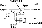
Fig. 6 has illustrated the embodiment that stops cropper according to of the present invention.
Embodiment
Usually, by data-flow analysis the source code program transformation is become data flow diagram.The straightforward procedure of carrying out data-flow analysis is: all outputs place in program begin.Find the instant source of each output.If it is operation, then replaces this operation, and it is connected to output with arc with node.If the source is a variable, then replaces this variable and be connected to output with arc.All arcs and node at the input that lacks appointment fully carry out repetition.
Fig. 1 a has illustrated original known data flow diagram.For reason clearly, in this article, the term node is used to the functional node in the designation data flow graph.Handle levels for 3 shown in this figure: top node 101,102,103 receive the input data in its input from one or more source, and these data will obtain handling when it flows through this figure.The actual mathematical that top node is carried out, logical OR process sexual function is specific to each realization, because it depends on the source code that data flow diagram comes from.For example, first node 101 can be to carrying out simple addition from the data of 2 inputs, Section Point 102 can deduct the data that first input receives from the data that second input receives, 2 data that the 3rd node 103 can for example receive with its input are carried out fixed-point multiplication.The input quantity of each node, actual treatment of carrying out in each node or the like realizes it certainly being different for difference, and is not limited to above-mentioned example.For example, node can be carried out complicated more calculating, even access external memory, and this will be described below.
Data flow to the Section Point level from the first node level, wherein are sent to the input of node 104 in this case by the output from node 101 and 102 from the data of node 101 and 102.According to the above discussion, node 104 is according to the information and executing particular task of its input reception.
After the processing of second level, data are sent to first of node 105 by the output from node 104 and import, and this node is positioned at tri-layer.Can find by Fig. 1, in the data of second input of node 105 reception from the output of the node 103 of level 1.Do not exist the fact of second layer minor node to mean the data (combinatorial delays of supposing each node place equates) that before the first input node place at node 105 can obtain data, will can obtain between the node 103 and 105 from node 103 in second input of node 105.In order to handle this situation efficiently, will provide triggering rule for each node, triggering rule has defined the condition that makes node that data are provided in its output place.
More specifically, triggering rule is the mechanism of the data stream in the control and data flow graph.By using triggering rule, in the functional mapping data according to node, data are sent to the output of node from input.Only when at the input of node necessary being data available, just can carry out consumption from the data of this input.Correspondingly, if there is no from the data (being the data item that subsequent node has necessarily been consumed the front) in the obstruction path of last calculating, then only to produce data in output place.Yet in some cases, can produce data, even legacy data blocks the path in output place; The legacy data of output place then will be replaced by new data.
The specification of general triggering rule generally includes:
1) at each input of node, in order to make the condition of this node consumption input data,
2) at each output of node, for make this node output place produce data condition and
3) condition of the function of XM.
Condition depends on the value of importing data usually, inputs or outputs the existence of place's valid data, the result of the function that is applied to import or the state of function, but can depend on any data that system can use in principle.
Set up general triggering rule by node 101-105, can control various programs and need not special-purpose control path at system.Yet,, can realize control stream at some special circumstances by triggering rule.Another special case is the system that does not have triggering rule, and wherein all node 101-105 only operate when all inputs at node 101-105 can obtain data.
The specific examples of the function of triggering rule can be provided by merge node.By this node, can flow by control data, and need not control stream.Merge node has 2 data inputs usually, wherein will select the data from one of them data input.In addition, it also has the control input that is used to select to obtain from it data input of data.Finally, it has a data output, transmits selected input data values in this data output place.
For example, suppose that node has 2 input T and F.On input C, receive the condition of Control Node, on output R, provide the result.Following triggering rule will produce data in output place of node, even only exist in the available data in input.In this case, if C=1 does not for example then have data need be present in input F place.That is, the condition of the data of the input of consumption node is:
(C=1AND?T=x)OR(C=0AND?F=x)
Wherein x represents to exist effective value.
In addition, provide the condition of data of output place of node to be:
(C=1AND?T=x)OR(C=0AND?F=x)
And the function of this node is:
R=IF(C==1)T?ELSE?F
The node that another kind is used for control data stream is a switch.Switching node has 2 output T and F usually, a data input D and a control input C.When data inputs and control input can obtain data, node will locate to provide data in one of its output.Consumption from the condition of the data of input is:
C=x?AND?D=x
And provide the condition of data to be in output place:
T:C=1?AND?D=x
F:C=0?AND?D=x
And the function of node is:
T=IF(C==1)D
F=IF(C==0)D
Fig. 1 b has illustrated the merging of the data stream that is used for control data stream machine and the use of switching node.In this case, data flow computer is according to the value of following function calculation s:
Follow above-mentioned inference, can may set up triggering rule by node, for example: very (True-gates) (data input D, a control input C exports R and function R=IF (C==1) D for) at all types of; Uncertain preferential merging (2 data are imported D1 and D2, export R and function R=IF (D1) D1 ELSE IF (D2) D2 for one); Addition (2 data input D1 and D2, output R and function R=D1+D2); Duplicate (data input D, a control input C, output R and function R=D); With boolean stream (Boolstream) (not input, output R and function:
R=IF (state==n) is provided with state=0, returns 1
ELSE increases progressively state, returns 0
Yet, be independent of node functionally, after the data of handling its input, node 105 provides the end value of data processing in its output place.In this case, the data of 5 inputs produce data in single output place.
When tight inspection data flow computer semantic, can observe, those semantemes are very similar to the mode of digital circuit operation, especially on register transfer level (RTL).In data flow computer, data are positioned on the arc, and are delivered to another arc by the functional node of data being carried out certain operation from an arc.In digital circuit, data reside in the register, and transmit between register by the combinational logic of data being carried out certain function.Because this tight similarity is present between the operation of the semanteme of data flow computer and digital circuit, therefore can directly realize data flow computer in digital circuit.This means that data pass through the propagation of data flow computer and can realize in digital circuit, and the analog machine that need not to be similar to state machine is carried out the operation of data flow computer.Replace,, can directly realize data flow computer by replacing node with combinational logic and replacing arc with register or other short-access storage element of concurrent access independently.
Its advantage mainly is an execution speed.This realization meeting can utilize the concurrency than the realization higher level of passing through processor or other state machine.It is more prone to streamline, and the level of concurrency can have meticulousr granularity.Should be noted that and avoid the user mode machine to realize that data flow computer itself still allows the node of data flow computer to comprise state machine.
Optional description of the present invention will be that the specified register node is inserted between the functional node of data flow diagram, and limit (edge) is realized as simple line.For clear, we with node as combinational logic and limit as register, rather than functions of use node, the mode on register node and limit is described the present invention.
Fig. 2 has illustrated the of the present invention first simple embodiment.More specifically, this figure illustrates the hardware realization of the data flow diagram of Fig. 1.The functional node 101-105 of Fig. 1 is substituted by node 201-205, the mathematics or the logical function that define in the data flow diagram of node 201-205 execution graph 1.This function can be carried out by combinational logic, but also can for example carry out by state machine or certain pipelining equipment.
In Fig. 2, for example line of register 206-215 or trigger and the fast parallel data storage hardware connection between the different nodes of alternate figures 1.The data that provide in output place of node 201-205 are stored among the register 206-215, so that instant or follow-up another node 201-205 that is sent to.As can be seen from the figure, register 213 makes it possible to store the output valve from node 203, handles the data from node 201 and 202 simultaneously in node 204.If between different node 201-205, there is not available register 206-215, postpone the data potentially unstable of the input of some node (change value) by various combination owing to front node in the same paths.
For example, suppose (by register 206-210) is provided in the input of node 201-203 first group of data.After the processing in node, will can obtain data in output place of node 201-203.Node 201 and 202 then will provide data to node 204, and node 203 will provide data to node 205 simultaneously.Because node 205 also receives data from node 204, must before being sent to node 205, data in node 204, handle these data.If provided new data in the input of node 201-203 before data dissemination is by node 204, then perhaps the output of node 203 change.Therefore, the data of the input of node 205 are promptly compared with the data that node 205 provides not correct, and the data that node 204 provides come from the moment early.
Above-mentioned inference is the inference of simplifying.In fact, need senior clock module, communication protocol, additional node/register or accessory logic circuit are correct with the data that assurance offers different nodes.Fig. 3 shows the most direct solution to problem, and wherein additional node 316 and related register 317 thereof have been inserted in the data routing.Node 316 is carried out NOP (not having operation), does not therefore change the data that its input provides.By inserting node 316, in each data routing of figure, obtain equal length.Effect is that the arc between 203 and 205 can have 2 unit now.
Fig. 4 a illustrates another solution, wherein for each node 401 provides additional signal lines, is used for providing correct data constantly at each.The first additional wire transmission " effectively (valid) " signal 402, its indication front node has stable data in its output place.Similarly, when the data stabilization of output place of node 401, the subsequent node of node 401 in data routing provides " effective " signal 403.By this process, each node can be determined the state of the data of its input.
In addition, the second additional wire transmission " stops (stall) " signal 404, " stopping " signal 404 receive any additional data in its input to last node indication present node 401 is offhand.Similarly, node 401 also the subsequent node from data routing receive " stopping " line 405.By using stop line, can stop the data stream in the particular path temporarily.If have the time-consuming data processing of uncertain delay in some node execution constantly, for example circulation or memory access, this is important so.The use of stop signal only is one embodiment of the present of invention.According to the agreement of selecting, can use some other signals.Example comprises " data consumption ", and " ready reception ", " affirmation " or " do not confirmed " signal and based on the signal of pulse or transformation, rather than high or low signal.Other signal mode also is fine." effectively " use of signal makes it possible to represent the existence of data on the arc or does not exist.So, not only can construct the synchronous data flow machine, and can construct static and dynamic dataflow machine." effectively " signal needn't be implemented as dedicated signal lines, and it can be realized with some alternate manners, is similar to and selects the special data value to represent " empty (null) " value.As for stop signal, there are many other possible signal modes.For clear, the remainder of this paper will only be quoted and stop and useful signal.It is simple that function of the present invention is expanded to other signal mode.
Because the existence of specific stop signal can realize more high-level efficiency.Even stop signal makes node can know that following arc of this moment is complete, its can be able to accept output token in next clock period.Do not having under the situation of stop signal, node must wait for, do not have valid data on the arc below before can triggering at it.This means at each other cycle arc at least to be sky, thus the efficient of losing.
Fig. 4 b illustrates and is used at node 401 generations effective 402,403 and the example that stops the logical circuit of 404,405 signals.Circuit shown in this figure is used in the node that triggers in the time can obtaining data in all inputs.Usually, triggering rule may be complicated more, and must set up according to the function of individual node 401.
Fig. 4 c respective description the example of the logical circuit that uses in the register between the node 406 in the data flow computer.If this circuit guarantees destination node and do not prepare as yet to accept data that then register will keep its data, and with this advisory source node.If register is empty, if or destination node will accept the current content of register, it also will accept new data.In this drawing, for clearly 407 and data outputs 408 of data input of a reason diagram.Yet the actual quantity that it is emphasized that input and output depends on the highway width (promptly being marked with how many bit wides) of system.
Under the situation of complex data stream machine, stop line is compared with signal velocity and may be become very long.This can cause stop signal not arrive needing in the path each node of stopping, causes loss of data (data that promptly also do not have to handle are rewritten by new data).
The common methods that 2 head it offs are arranged.Balanced very modestly stop signal travel path in time arrives all destination registers to guarantee it.Alternatively, after the piece that can stop, placing fifo buffer, thereby avoid fully in this piece, using stop signal.When pipeline data when streamline flows out, FIFO is used to collect pipeline data.For bigger streamline piece, last solution is very difficult to realize and is consuming time.The latter then needs bigger buffer zone so that can preserve the whole data acquisition that may exist in this piece.
The better mode of tackling this limit signal velocity of propagation be utilize be called " stopping cropper (stall cutter) " as the graphic feature of Fig. 6.Stopping cropper is to receive stop line and it is postponed the register of one-period from subsequent node basically.The pattern length that this has cut off stop signal at this point.
When stopping cropper and receive effective stop signal, it cushions the data from last node during a processing cycle, and simultaneously stop signal is postponed identical amount.By postponing stop signal and buffering input data, even guarantee to use very long stop line also not have data to be lost.Stop cropper reduced data round-robin realization greatly, especially pipeline data circulation.In this case, the many variations that are used for the agreement of control data stream will need stop signal to take with identical by the round-robin data, usually opposite path.This will produce the Combined Cycle of stop signal.Stop cropper by in circulation, placing, can avoid this Combined Cycle, will be difficult to many agreements that maybe can not realize thereby permission is used.
Finally, the angle of data dissemination is observed from data flow computer, and it is transparent stopping cropper.This means and to stop cropper with the automated manner increase as required.
Fig. 5 a illustrates an alternative embodiment of the invention, and wherein data routing obtains equilibrium by the node merging among the figure.For the design of using the global clock signal, determine the highest possibility clock frequency by the slowest processing unit.This means and have the ability to be confined to the enterprising line operate of frequency that is provided with by the slowest unit at each processing unit that high frequency treatment is operated.Therefore, expectation obtains to have the processing unit of equal or almost equal size, because there is not the unit that other unit will be slowed down.Even for the design that does not have the global clock signal, 2 data paths during branch is calculated have equal length, and promptly the number of nodes that exists in each data routing is identical also is favourable.By guaranteeing that data routing has equal length, the calculating in 2 branches will be carried out with identical speed.
Shown in Fig. 5 a, 2 nodes 304 of Fig. 3 and 305 have been merged into a node 504.As mentioned above, can carry out this and handle, so that the length in balanced different pieces of information path, or the overall process speed of optimal design.
Come XM to merge by the register of eliminating between some node, wherein along with merge node becomes bigger, number of nodes will reduce.By merge selected node systematically, it is equal substantially that the combined depth of node becomes, and the processing speed between the different node obtains equilibrium.
When merge node, its function is separately also merged.This is undertaken by connecting the Different Logic unit without any distributor ground.Along with node is merged, new triggering rule must be determined so that make node when needs, provide data in its output place.
More specifically, as shown in Fig. 5 b,, produce the new node 509 that the equal number with the input and output arc that has with start node deducts the arc that is connected 2 nodes 507,508 that are combined when merging 2 nodes 507,508 o'clock.As mentioned above, for being similar to addition, the basic function node that multiplies each other or the like, triggering when triggering rule will exist data and all output freely to receive data in all inputs triggering rule of nm-triggering rule (below be called).Merge the new node 509 that 2 such nodes 507,508 have generation 3 inputs and an output.From 2 inputs of addition, from 2 inputs of multiplying each other, an input of using in the connection between 2 nodes provides 3 inputs of merge node.From an output of addition, provide single output from merge node from multiply each other one output and an output that is used for being connected 2 nodes.The triggering rule of merge node will need the data-triggered of all its 3 inputs.In fact, any merging itself with node of nm-triggering rule will have the nm-triggering rule, although the quantity of input and output will change.By directly being connected to the input of other combination block, merge the function of initial 2 nodes 507,508 from the output of first combination block according to the previous arc that connects them.The register of the arc between the previous expression node is eliminated.So the result is bigger combination block.
Therefore, for the data that need its input all the time and the node of data is provided in its output place all the time, for example carry out the node of arithmetic function, the triggering rule of merge node will be identical with start node.
As mentioned above, the use of functional programming language is for realizing that in data flow computer huge parallelism is necessary.According to the present invention, handle the problem of spinoff by mark.Be called the special marking of example mark (instance token) by use, can control the quantity that may visit spinoff, and the order that takes place of these visits.
Except the general data input, wish to use each node of spinoff must have the exclusive data input that is used for the example mark relevant with related spinoff.Except the data input that is used for the example mark, it also must have the output that is used for the example mark.The data routing that is used for the example mark serves as other data routing of data flow computer, and promptly node must have the data in all relevant inputs before it can carry out its specific operation.
Need the triggering rule of the node of visit spinoff to make it in example mark input (being example mark itself), to have data.When the visit finished spinoff, node discharges the example mark of its output place.This output then can be connected to the example mark input of the subsequent node that needs the effect of visit identical minor.By this process, visit at needs between all nodes of specific spinoff and set up the example path label.Example path label decision node obtains the order to the visit of spinoff.
Therefore, for specific spinoff (for example storer or indicator), the example mark that exists one or more to move along example path label.Because need having data in its input, all nodes in this chain obtain visit, the quantity of visiting when can retrain spinoff by the data cell quantity (promptly limiting the quantity of example mark) on the restriction example flag data path to spinoff.If have only an example mark to be allowed to be present on the example path label, then guarantee never to visit spinoff simultaneously from two or more nodes a particular moment.In addition, clearly determine the order of visit spinoff by the example path label.If it is safe making a more than node visit spinoff during some environment, then can in the path, introduce a more than example mark simultaneously.It also can be safe cutting apart the example path label, thereby the example mark is copied to two paths cutting apart.
For example, when visit during, if two paths only comprise from the reading of storer, then cut apart normally safety of example path label as the storer of spinoff.In this case, visit will be by the Memory Controller voluntary arbitration in the time of to storer, and still because the execution sequence that reads does not influence each other, this is safe.On the contrary, if 2 paths comprise write, 2 orders that write of then actual execution will be necessary, because this will determine what value storer finally preserves.In this case, the example path label can not be cut apart safely.
After on example path label single-threaded, being placed on some example marks each other the streamline of ordinary representation by different " generations (generation) " calculated visit to storer.If for example known because their same sections of reference-to storage not, thus 2 generations have nothing to do, will be safe after then a plurality of example marks being inserted in each other.
Also can after each other, place visit to some different spinoffs (for example storer or other input or output the unit).This will have the effect of clearly determining the order of the visit of each spinoff of each example mark on the path.For example, can be placed on before the writing of output unit on the example path label from reading of input block, if some example marks are present on the path simultaneously, then the general sequence of read and write may be undetermined, but will there be clearly sequencing in each the single instance mark on the path between spinoff.
Finally, when design during digital circuit, data flow computer that can mixing of different types.For example, can make the part of the circulation of the iteration that has the quantity that depends on data in the static data flow machine as the dynamic dataflow machine.Like this can the executed in parallel iteration, and in the static data flow machine, be can not be so.Under the situation of the complete indicia matched system that does not have the dynamic dataflow machine, the local dynamic part of such static data flow machine can be operated.On the contrary, only need to guarantee that mark withdraws from dynamic part according to the same sequence that they enter dynamic part.Because the remainder of machine is static and mark do not reset preface, this will make indicia matched.
At each mark (token) by entering recurrence with sequence number mark (tagging) and use buffer zone to collect after mark that (out of order) not in order finish recurrence finishes recurrence, can rearrange mark with correct order.More specifically, after recursion step, arrange buffer zone.If mark does not withdraw from recurrence in order, it will be placed in the buffer zone, up to the underlined recurrence that withdraws from lower sequence number.Therefore, how many marks the decision of the size of buffer zone has to withdraw from recurrence out of turn, guarantees that simultaneously mark can correctly be arranged after recurrence is finished.In some cases, can know that the order of the mark that withdraws from recurrence has nothing to do, for example if carry out the simple summation of the value of the mark that withdraws from recurrence.In such cases, can omit with sequence number flag data mark and buffer zone.
Except that the data associated cyclic, local indicia matched and the use that resets sequence pattern also can be used to node or subgraph other type reset preface.
The present invention has been described with reference to preferred embodiment.Yet defined as appended claims, other embodiment except that disclosed embodiment here also within the scope of the invention.
Claims (77)
1. one kind produces the method for the digital control parameter be used to realize DLC (digital logic circuit) by diagram, and described diagram comprises the functional node with at least one input or at least one output, and the connection of the interconnection between the deixis node, it is characterized in that
At the digital control parameter of each functional node definition specify hardware unit of this figure,
At between the functional node each connect definition specify hardware unit digital control parameter and
Digital control parameter at the triggering rule in each functional node definition specify hardware unit of this figure.
2. the method for claim 1 is characterized in that this diagram is a digraph.
3. method as claimed in claim 1 or 2 is characterized in that producing this diagram by the high-level source code specification.
4. as the described method of claim 1-3, it is characterized in that specifying the digital control parameter of the on-chip memory unit of concurrent access independently at least one the connection definition between the functional node.
5. as the described method of claim 1-4, it is characterized in that digital control parameter at least one the connection definition designation number register between the functional node.
6. as the described method of claim 1-4, it is characterized in that specifying the digital control parameter of at least one trigger at least one the connection definition between the functional node.
7. as the described method of claim 1-4, it is characterized in that being to specify the digital control parameter of at least one latch at least one the connection definition between the functional node.
8. as the described method of any claim in front, it is characterized in that digital control parameter at each functional node definition given combination logic.
9. as the described method of claim 1-7, it is characterized in that specifying the digital control parameter of at least one state machine at least one functional node definition.
10. equipment that produces the digital control parameter be used to realize DLC (digital logic circuit) by diagram, described diagram comprises the functional node with at least one input or at least one output, and the connection of the interconnection between the deixis node, it is characterized in that this equipment is suitable for
At the digital control parameter of each functional node definition specify hardware unit of this figure,
At between the functional node each connect definition specify hardware unit digital control parameter and
Digital control parameter at the triggering rule in each functional node definition specify hardware unit of this figure.
11. equipment as claimed in claim 10 is characterized in that this diagram is a digraph.
12., it is characterized in that producing this diagram by the high-level source code specification as claim 10 or 11 described equipment.
13., it is characterized in that this equipment is suitable for specifying the digital control parameter of the on-chip memory unit of concurrent access independently at least one the connection definition between the functional node as the described equipment of claim 10-12.
14., it is characterized in that this equipment is suitable for the digital control parameter at least one the connection definition designation number register between the functional node as the described equipment of claim 10-13.
15., it is characterized in that this equipment is suitable for specifying at least one the connection definition between the functional node the digital control parameter of at least one trigger as the described equipment of claim 10-13.
16., it is characterized in that this equipment is suitable for specifying at least one the connection definition between the functional node the digital control parameter of at least one latch as the described equipment of claim 10-13.
17., it is characterized in that this equipment is suitable for the digital control parameter at each functional node definition given combination logic as the described equipment of claim 10-16.
18., it is characterized in that this equipment is suitable for specifying at each functional node definition the digital control parameter of at least one state machine as the described equipment of claim 10-16.
19. a data flow computer is characterized in that
Carry out first group of hardware cell of data conversion,
Interconnect first group of hardware cell second group of hardware cell and
Set up the electronic circuit of at least one triggering rule at each hardware cell of first group of hardware cell.
20. data flow computer as claimed in claim 19 is characterized in that this diagram is a digraph.
21., it is characterized in that at least one unit of second group of hardware cell has the form of the on-chip memory unit of concurrent access independently as claim 19 or 20 described data flow computers.
22., it is characterized in that at least one unit of second group of hardware cell has the form of register as the described data flow computer of claim 19-21.
23., it is characterized in that at least one unit of second group of hardware cell has the form of trigger as the described data flow computer of claim 19-21.
24., it is characterized in that at least one unit of second group of hardware cell has the form of latch as the described data flow computer of claim 19-21.
25., it is characterized in that first group of hardware cell has the form of combinational logic as the described data flow computer of claim 19-24.
26., it is characterized in that at least one unit in first group of hardware cell has the form of at least one state machine as the described data flow computer of claim 19-24.
27. as the described data flow computer of claim 19-26, it is characterized in that by ASIC, FPGA, CPLD or other PLD realize data flow computer.
28. the computer program in the storer that directly can be loaded into the electronic equipment with digital computer capabilities comprises when described product being used for the software code part of step that enforcement of rights requires any claim of 1-9 during by described electronic equipment operation.
29. computer program as claimed in claim 28, it is embodied on the computer-readable medium.
30. method that produces the digital control parameter be used to realize DLC (digital logic circuit) by diagram, described diagram comprises the connection of the interconnection between functional node and the deixis node, described functional node comprises at least one input or at least one output, it is characterized in that
Specify the digital control parameter that merges hardware cell at least the first and second functional nodes definition, described digital control parameter is specified and is merged hardware cell carrying out the function of first and second functional nodes,
The hardware cell that produces at the merging by first and second functional nodes defines the digital control parameter of specifying triggering rule.
31. method as claimed in claim 30, the digital control parameter that is wherein produced are specified the direct connection between at least one input of at least one output of first functional node and second functional node.
32., it is characterized in that specifying the digital control parameter of the triggering rule of the triggering rule that is different from first and second functional nodes at merging the hardware cell definition as claim 30 or 31 described methods.
33. equipment that is used for producing the digital control parameter be used to realize DLC (digital logic circuit) by diagram, described diagram comprises the connection of the interconnection between functional node and the deixis node, described functional node comprises at least one input or at least one output, it is characterized in that this equipment is suitable for:
Specify the digital control parameter that merges hardware cell at least the first and second functional nodes definition, described digital control parameter is specified and is merged hardware cell carrying out the function of first and second functional nodes,
The hardware cell that produces at the merging by first and second functional nodes defines the digital control parameter of specifying triggering rule.
34. equipment as claimed in claim 33, wherein this equipment is suitable for defining the direct-connected digital control parameter between at least one input of at least one output of specifying first functional node and second functional node.
35., it is characterized in that this equipment is suitable for specifying the digital control parameter of the triggering rule of the triggering rule that is different from first and second functional nodes at merging the hardware cell definition as claim 33 or 34 described equipment.
36. the computer program in the storer that directly can be loaded into the electronic equipment with digital computer capabilities comprises when described product being used for the software code part of step that enforcement of rights requires any claim of 30-32 during by described electronic equipment operation.
37. computer program as claimed in claim 36, it is embodied on the computer-readable medium.
38. a method that allows the first and second interconnected hardware unit in the log-on data stream machine, described method comprises:
For first hardware cell provides first unit of digital data, wherein providing of first unit of digital data allows to start first hardware cell in first hardware cell,
Transmit first unit of digital data to second hardware cell from first hardware cell, wherein the reception of first unit of digital data allow to start second hardware cell in second hardware cell, and first unit of digital data is surrendered No starting first hardware cell from first hardware cell.
39. method as claimed in claim 38 wherein can provide second unit of digital data for first hardware cell after the surrendering of first unit of digital data.
40., wherein in first hardware cell, produce unit of digital data as claim 38 or 39 described methods.
41. as claim 38 or 39 described methods, wherein unit of digital data produces and is sent to first hardware cell in discrete hardware cell.
42. as any one described method among the claim 38-41, wherein first hardware cell is surrendered and returned to unit of digital data from second hardware cell.
43. a data flow computer that comprises the first and second interconnected hardware unit is characterized in that
For first hardware cell provides first unit of digital data, and first hardware cell is suitable for being allowed to when described first unit of digital data is present in first hardware cell starting, and
First hardware cell is suitable for transmitting first unit of digital data to second hardware cell from first hardware cell, wherein second hardware cell is suitable for being allowed to start as the result of the reception of at least the first unit of digital data, and first hardware cell is suitable for as the result who surrenders of unit of digital data and the startup that is under an embargo.
44. data flow computer as claimed in claim 43, wherein first hardware cell is suitable for being provided second unit of digital data after second hardware cell transmits first unit of digital data.
45. as claim 43 or 44 described data flow computers, wherein first hardware cell is suitable for producing unit of digital data.
46. as claim 43 or 44 described data flow computers, wherein first hardware cell is suitable for from discrete hardware elements receiving digital data unit.
47. as the described data flow computer of claim 43-46, it is characterized in that by ASIC, FPGA, CPLD or other PLD realize data flow computer.
48. method that guarantees the data integrity in the data flow computer, at least one stop line that wherein is connected at least the first and second hardware cells is so arranged, make data routing is provided in data flow computer, when stop signal is enlivened on this stop line, this data routing is provided for the time-out data stream, this data stream advances to second hardware cell from first hardware cell in data routing during the processing cycle, it is characterized in that
First input in the first on-chip memory unit receives stop signal from second hardware cell,
First input in the second on-chip memory unit receives data from first hardware cell,
The stop signal that will receive data and reception in the first and second on-chip memory unit cushions at least one processing cycle,
First output place in the first on-chip memory unit provides the stop signal of buffering to first hardware cell, and
First output place in the second on-chip memory unit provides the data of buffering to second hardware cell.
49. method as claimed in claim 48, wherein at least one on-chip memory unit is a register.
50. equipment that guarantees the data integrity in the data flow computer, at least one stop line that wherein is connected at least the first and second hardware cells is so arranged, make data routing is provided in data flow computer, when stop signal is enlivened on this stop line, this data routing is provided for the time-out data stream, this data stream advances to second hardware cell from first hardware cell in data routing during the processing cycle, it is characterized in that this equipment is suitable for
First input in the first on-chip memory unit receives stop signal from second hardware cell,
First input in the second on-chip memory unit receives data from first hardware cell,
The stop signal that will receive data and reception in the first and second on-chip memory unit cushions at least one processing cycle,
First output place in the first on-chip memory unit provides the stop signal of buffering to first hardware cell, and
First output place in the second on-chip memory unit provides the data of buffering to second hardware cell.
51. method as claimed in claim 48, wherein at least one on-chip memory unit is a register.
52. method that produces the digital control parameter be used to realize DLC (digital logic circuit) by diagram, described diagram comprises the connection of the interconnection between functional node and the deixis node, described functional node has at least one input or at least one output, it is characterized in that
At the connection between functional node or functional node definition specify at least the first group hardware cell digital control parameter and
Definition specifies at least one to reset the digital control parameter of preface hardware cell, this at least one reset the preface hardware cell data cell of sending from least one first group of hardware cell sorted, make data cell send from first group of hardware cell according to entering the identical order of the order of first group of hardware cell with them.
53. method as claimed in claim 52 is characterized in that this diagram is a digraph.
54., it is characterized in that producing this diagram by the high-level source code specification as claim 52 or 53 described methods.
55., it is characterized in that specifying the digital control parameter of the on-chip memory unit of concurrent access independently at least one the connection definition between the functional node as any one described method among the claim 52-54.
56., it is characterized in that digital control parameter at least one the connection definition designation number register between the functional node as any one described method among the claim 52-55.
57., it is characterized in that specifying the digital control parameter of at least one trigger at least one the connection definition between the functional node as any one described method among the claim 52-55.
58., it is characterized in that specifying the digital control parameter of at least one latch at least one the connection definition between the functional node as any one described method among the claim 52-55.
59. method that produces the digital control parameter be used to realize DLC (digital logic circuit) by diagram, described diagram comprises the connection of the interconnection between functional node and the deixis node, described functional node has at least one input or at least one output, it is characterized in that this equipment is suitable for
At the connection between functional node or functional node definition specify at least the first group hardware cell digital control parameter and
Definition specifies at least one to reset the digital control parameter of preface hardware cell, this at least one reset the preface hardware cell data cell of sending from least one first group of hardware cell sorted, make data cell send from first group of hardware cell according to entering the identical order of the order of first group of hardware cell with them.
60. equipment as claimed in claim 59 is characterized in that this diagram is a digraph.
61., it is characterized in that producing this diagram by the high-level source code specification as claim 59 or 60 described equipment.
62., it is characterized in that this equipment is suitable for specifying the digital control parameter of the on-chip memory unit of concurrent access independently at least one the connection definition between the functional node as any one described equipment among the claim 59-61.
63., it is characterized in that this equipment is suitable for the digital control parameter at least one the connection definition designation number register between the functional node as the described equipment of claim 59-62.
64., it is characterized in that this equipment is suitable for specifying at least one the connection definition between the functional node the digital control parameter of at least one trigger as the described equipment of claim 59-62.
65., it is characterized in that this equipment is suitable for specifying at least one the connection definition between the functional node the digital control parameter of at least one latch as the described equipment of claim 59-62.
66. a data flow computer is characterized in that
Carry out data conversion first group of hardware cell and
At least one resets the preface hardware cell, this at least one reset the preface hardware cell data cell of sending from least one first group of hardware cell sorted, make data cell send from first group of hardware cell according to entering the identical order of the order of first group of hardware cell with them.
67., it is characterized in that this diagram is a digraph as the described data flow computer of claim 66.
68., it is characterized in that at least one unit of second and the 3rd group of hardware cell has the form of the on-chip memory unit of concurrent access independently as claim 66 or 67 described data flow computers.
69., it is characterized in that at least one unit of second and the 3rd group of hardware cell has the form of register as the described data flow computer of claim 66-68.
70., it is characterized in that at least one unit of second and the 3rd group of hardware cell has the form of trigger as the described data flow computer of claim 66-68.
71., it is characterized in that at least one unit of second and the 3rd group of hardware cell has the form of latch as the described data flow computer of claim 66-68.
72. as the described data flow computer of claim 66-71, it is characterized in that by ASIC, FPGA, CPLD or other PLD realize data flow computer.
73. the computer program in the storer that directly can be loaded into the electronic equipment with digital computer capabilities comprises when described product being used for the software code part of step that enforcement of rights requires any claim of 52-58 during by described electronic equipment operation.
74. as the described computer program of claim 73, it is embodied on the computer-readable medium.
75., wherein produce this diagram by the high-level source code specification as any one described method in the claim 30 to 32.
76., wherein produce this diagram by the high-level source code specification as any one described equipment in the claim 30 to 35.
77. as the described data flow computer of claim 43-46, wherein first hardware cell is surrendered and returned to unit of digital data from second hardware cell.
Applications Claiming Priority (2)
| Application Number | Priority Date | Filing Date | Title |
|---|---|---|---|
| SE0300742A SE0300742D0 (en) | 2003-03-17 | 2003-03-17 | Data Flow Machine |
| SE03007424 | 2003-03-17 |
Publications (1)
| Publication Number | Publication Date |
|---|---|
| CN1781092A true CN1781092A (en) | 2006-05-31 |
Family
ID=20290710
Family Applications (1)
| Application Number | Title | Priority Date | Filing Date |
|---|---|---|---|
| CNA2004800113714A Pending CN1781092A (en) | 2003-03-17 | 2004-03-17 | Data flow machine |
Country Status (6)
| Country | Link |
|---|---|
| US (1) | US20060101237A1 (en) |
| EP (1) | EP1609078B1 (en) |
| JP (1) | JP2006522406A (en) |
| CN (1) | CN1781092A (en) |
| SE (1) | SE0300742D0 (en) |
| WO (1) | WO2004084086A1 (en) |
Cited By (4)
| Publication number | Priority date | Publication date | Assignee | Title |
|---|---|---|---|---|
| CN101179516B (en) * | 2006-11-10 | 2010-06-09 | 北京航空航天大学 | Digraph based data distributing method |
| CN106155755A (en) * | 2015-06-03 | 2016-11-23 | 上海红神信息技术有限公司 | Program compiling method and compiler |
| CN110149801A (en) * | 2015-05-05 | 2019-08-20 | 华为技术有限公司 | System and method for carrying out data flow diagram conversion in the processing system |
| WO2020168474A1 (en) * | 2019-02-20 | 2020-08-27 | 深圳大学 | Method and apparatus for improving operation efficiency of dataflow machine, device and storage medium |
Families Citing this family (27)
| Publication number | Priority date | Publication date | Assignee | Title |
|---|---|---|---|---|
| US7571303B2 (en) * | 2002-10-16 | 2009-08-04 | Akya (Holdings) Limited | Reconfigurable integrated circuit |
| EP1784749A2 (en) | 2004-09-02 | 2007-05-16 | Logiccon Design Automation Ltd. | Method and system for designing a structural level description of an electronic circuit |
| US8510709B2 (en) * | 2009-06-01 | 2013-08-13 | National Instruments Corporation | Graphical indicator which specifies parallelization of iterative program code in a graphical data flow program |
| US9733914B2 (en) * | 2009-06-01 | 2017-08-15 | National Instruments Corporation | Loop parallelization analyzer for data flow programs |
| US9152668B1 (en) * | 2010-01-29 | 2015-10-06 | Asana, Inc. | Asynchronous computation batching |
| US10157060B2 (en) | 2011-12-29 | 2018-12-18 | Intel Corporation | Method, device and system for control signaling in a data path module of a data stream processing engine |
| US10331583B2 (en) | 2013-09-26 | 2019-06-25 | Intel Corporation | Executing distributed memory operations using processing elements connected by distributed channels |
| US10572376B2 (en) | 2016-12-30 | 2020-02-25 | Intel Corporation | Memory ordering in acceleration hardware |
| US10558575B2 (en) | 2016-12-30 | 2020-02-11 | Intel Corporation | Processors, methods, and systems with a configurable spatial accelerator |
| US10515046B2 (en) | 2017-07-01 | 2019-12-24 | Intel Corporation | Processors, methods, and systems with a configurable spatial accelerator |
| US10469397B2 (en) | 2017-07-01 | 2019-11-05 | Intel Corporation | Processors and methods with configurable network-based dataflow operator circuits |
| US10515049B1 (en) | 2017-07-01 | 2019-12-24 | Intel Corporation | Memory circuits and methods for distributed memory hazard detection and error recovery |
| US11086816B2 (en) | 2017-09-28 | 2021-08-10 | Intel Corporation | Processors, methods, and systems for debugging a configurable spatial accelerator |
| US10496574B2 (en) | 2017-09-28 | 2019-12-03 | Intel Corporation | Processors, methods, and systems for a memory fence in a configurable spatial accelerator |
| US10564980B2 (en) * | 2018-04-03 | 2020-02-18 | Intel Corporation | Apparatus, methods, and systems for conditional queues in a configurable spatial accelerator |
| US11307873B2 (en) | 2018-04-03 | 2022-04-19 | Intel Corporation | Apparatus, methods, and systems for unstructured data flow in a configurable spatial accelerator with predicate propagation and merging |
| US10853073B2 (en) | 2018-06-30 | 2020-12-01 | Intel Corporation | Apparatuses, methods, and systems for conditional operations in a configurable spatial accelerator |
| US10891240B2 (en) | 2018-06-30 | 2021-01-12 | Intel Corporation | Apparatus, methods, and systems for low latency communication in a configurable spatial accelerator |
| US11200186B2 (en) | 2018-06-30 | 2021-12-14 | Intel Corporation | Apparatuses, methods, and systems for operations in a configurable spatial accelerator |
| US10678724B1 (en) | 2018-12-29 | 2020-06-09 | Intel Corporation | Apparatuses, methods, and systems for in-network storage in a configurable spatial accelerator |
| US11029927B2 (en) | 2019-03-30 | 2021-06-08 | Intel Corporation | Methods and apparatus to detect and annotate backedges in a dataflow graph |
| US10965536B2 (en) | 2019-03-30 | 2021-03-30 | Intel Corporation | Methods and apparatus to insert buffers in a dataflow graph |
| US10817291B2 (en) | 2019-03-30 | 2020-10-27 | Intel Corporation | Apparatuses, methods, and systems for swizzle operations in a configurable spatial accelerator |
| US10915471B2 (en) | 2019-03-30 | 2021-02-09 | Intel Corporation | Apparatuses, methods, and systems for memory interface circuit allocation in a configurable spatial accelerator |
| US11037050B2 (en) | 2019-06-29 | 2021-06-15 | Intel Corporation | Apparatuses, methods, and systems for memory interface circuit arbitration in a configurable spatial accelerator |
| US11907713B2 (en) | 2019-12-28 | 2024-02-20 | Intel Corporation | Apparatuses, methods, and systems for fused operations using sign modification in a processing element of a configurable spatial accelerator |
| WO2021211911A1 (en) * | 2020-04-16 | 2021-10-21 | Blackswan Technologies Inc. | Artificial intelligence cloud operating system |
Family Cites Families (36)
| Publication number | Priority date | Publication date | Assignee | Title |
|---|---|---|---|---|
| JPH0632056B2 (en) * | 1985-05-31 | 1994-04-27 | 松下電器産業株式会社 | Data processing device |
| JPS61276032A (en) * | 1985-05-31 | 1986-12-06 | Matsushita Electric Ind Co Ltd | Information processing device |
| US5021947A (en) * | 1986-03-31 | 1991-06-04 | Hughes Aircraft Company | Data-flow multiprocessor architecture with three dimensional multistage interconnection network for efficient signal and data processing |
| US4814978A (en) * | 1986-07-15 | 1989-03-21 | Dataflow Computer Corporation | Dataflow processing element, multiprocessor, and processes |
| US4972315A (en) * | 1987-03-10 | 1990-11-20 | Mitsubishi Denki Kabushiki Kaisha | Data flow machine |
| WO1990001192A1 (en) * | 1988-07-22 | 1990-02-08 | United States Department Of Energy | Data flow machine for data driven computing |
| US5680318A (en) * | 1990-12-21 | 1997-10-21 | Synopsys Inc. | Synthesizer for generating a logic network using a hardware independent description |
| US5666296A (en) * | 1991-12-31 | 1997-09-09 | Texas Instruments Incorporated | Method and means for translating a data-dependent program to a data flow graph with conditional expression |
| US5491640A (en) * | 1992-05-01 | 1996-02-13 | Vlsi Technology, Inc. | Method and apparatus for synthesizing datapaths for integrated circuit design and fabrication |
| US5297073A (en) * | 1992-08-19 | 1994-03-22 | Nec Electronics, Inc. | Integer divide using shift and subtract |
| JP3706397B2 (en) * | 1994-06-06 | 2005-10-12 | シャープ株式会社 | Data-driven information processing device |
| JPH08101861A (en) * | 1994-09-30 | 1996-04-16 | Toshiba Corp | Logic circuit synthesizing device |
| US6077315A (en) * | 1995-04-17 | 2000-06-20 | Ricoh Company Ltd. | Compiling system and method for partially reconfigurable computing |
| US5764951A (en) * | 1995-05-12 | 1998-06-09 | Synopsys, Inc. | Methods for automatically pipelining loops |
| US5854929A (en) * | 1996-03-08 | 1998-12-29 | Interuniversitair Micro-Elektronica Centrum (Imec Vzw) | Method of generating code for programmable processors, code generator and application thereof |
| US5838583A (en) * | 1996-04-12 | 1998-11-17 | Cadence Design Systems, Inc. | Optimized placement and routing of datapaths |
| US5974411A (en) * | 1997-02-18 | 1999-10-26 | Sand Technology Systems International, Inc. | N-way processing of bit strings in a dataflow architecture |
| US6606588B1 (en) * | 1997-03-14 | 2003-08-12 | Interuniversitair Micro-Elecktronica Centrum (Imec Vzw) | Design apparatus and a method for generating an implementable description of a digital system |
| US5966534A (en) * | 1997-06-27 | 1999-10-12 | Cooke; Laurence H. | Method for compiling high level programming languages into an integrated processor with reconfigurable logic |
| JP3850531B2 (en) * | 1997-10-21 | 2006-11-29 | 株式会社東芝 | Reconfigurable circuit design device and reconfigurable circuit device |
| US6075935A (en) * | 1997-12-01 | 2000-06-13 | Improv Systems, Inc. | Method of generating application specific integrated circuits using a programmable hardware architecture |
| RU2148857C1 (en) * | 1998-02-20 | 2000-05-10 | Бурцев Всеволод Сергеевич | Computer system |
| US6145073A (en) * | 1998-10-16 | 2000-11-07 | Quintessence Architectures, Inc. | Data flow integrated circuit architecture |
| US6625797B1 (en) * | 2000-02-10 | 2003-09-23 | Xilinx, Inc. | Means and method for compiling high level software languages into algorithmically equivalent hardware representations |
| JP3722351B2 (en) * | 2000-02-18 | 2005-11-30 | シャープ株式会社 | High level synthesis method and recording medium used for the implementation |
| JP3796390B2 (en) * | 2000-04-27 | 2006-07-12 | シャープ株式会社 | Data-driven information processing device |
| KR100345009B1 (en) * | 2000-08-14 | 2002-07-20 | 주식회사 에이디칩스 | Asynchronous control circuit generation method |
| US20020178432A1 (en) * | 2000-08-17 | 2002-11-28 | Hyungwon Kim | Method and system for synthesizing a circuit representation into a new circuit representation having greater unateness |
| JP2002123563A (en) * | 2000-10-13 | 2002-04-26 | Nec Corp | Compiling method, composing device, and recording medium |
| US6711717B2 (en) * | 2001-10-11 | 2004-03-23 | California Institute Of Technology | Method and system for compiling circuit designs |
| JP4082653B2 (en) * | 2001-11-15 | 2008-04-30 | 松下電器産業株式会社 | High level synthesis method and high level synthesis apparatus |
| EP1514198A2 (en) * | 2002-06-03 | 2005-03-16 | Koninklijke Philips Electronics N.V. | Reconfigurable integrated circuit |
| US7065665B2 (en) * | 2002-10-02 | 2006-06-20 | International Business Machines Corporation | Interlocked synchronous pipeline clock gating |
| US6983456B2 (en) * | 2002-10-31 | 2006-01-03 | Src Computers, Inc. | Process for converting programs in high-level programming languages to a unified executable for hybrid computing platforms |
| WO2004072796A2 (en) * | 2003-02-05 | 2004-08-26 | Arizona Board Of Regents | Reconfigurable processing |
| US20090119484A1 (en) * | 2005-10-18 | 2009-05-07 | Stefan Mohl | Method and Apparatus for Implementing Digital Logic Circuitry |
-
2003
- 2003-03-17 SE SE0300742A patent/SE0300742D0/en unknown
-
2004
- 2004-03-17 CN CNA2004800113714A patent/CN1781092A/en active Pending
- 2004-03-17 WO PCT/SE2004/000394 patent/WO2004084086A1/en active Application Filing
- 2004-03-17 EP EP04721412.7A patent/EP1609078B1/en not_active Expired - Lifetime
- 2004-03-17 JP JP2006507967A patent/JP2006522406A/en active Pending
-
2005
- 2005-09-16 US US11/227,997 patent/US20060101237A1/en not_active Abandoned
Cited By (4)
| Publication number | Priority date | Publication date | Assignee | Title |
|---|---|---|---|---|
| CN101179516B (en) * | 2006-11-10 | 2010-06-09 | 北京航空航天大学 | Digraph based data distributing method |
| CN110149801A (en) * | 2015-05-05 | 2019-08-20 | 华为技术有限公司 | System and method for carrying out data flow diagram conversion in the processing system |
| CN106155755A (en) * | 2015-06-03 | 2016-11-23 | 上海红神信息技术有限公司 | Program compiling method and compiler |
| WO2020168474A1 (en) * | 2019-02-20 | 2020-08-27 | 深圳大学 | Method and apparatus for improving operation efficiency of dataflow machine, device and storage medium |
Also Published As
| Publication number | Publication date |
|---|---|
| US20060101237A1 (en) | 2006-05-11 |
| JP2006522406A (en) | 2006-09-28 |
| WO2004084086A8 (en) | 2005-02-24 |
| EP1609078A1 (en) | 2005-12-28 |
| WO2004084086A1 (en) | 2004-09-30 |
| EP1609078B1 (en) | 2016-06-01 |
| SE0300742D0 (en) | 2003-03-17 |
Similar Documents
| Publication | Publication Date | Title |
|---|---|---|
| CN1781092A (en) | Data flow machine | |
| Nane et al. | A survey and evaluation of FPGA high-level synthesis tools | |
| Hauck et al. | Reconfigurable computing: the theory and practice of FPGA-based computation | |
| Teifel et al. | An asynchronous dataflow FPGA architecture | |
| Bondalapati et al. | Reconfigurable computing systems | |
| Cardoso et al. | Compilation techniques for reconfigurable architectures | |
| US7401333B2 (en) | Array of parallel programmable processing engines and deterministic method of operating the same | |
| Flynn et al. | Computer system design: system-on-chip | |
| CN1653446A (en) | High-performance hybrid processor with configurable execution units | |
| JP2006522406A5 (en) | ||
| EP1941354A2 (en) | Method and apparatus for implementing digital logic circuritry | |
| Svensson | Evolution in architectures and programming methodologies of coarse-grained reconfigurable computing | |
| Bergmann et al. | QUKU: a dual-layer reconfigurable architecture | |
| Hauck et al. | Software technologies for reconfigurable systems | |
| Cong et al. | Simultaneous resource binding and interconnection optimization based on a distributed register-file microarchitecture | |
| Peng et al. | Automated synthesis for asynchronous FPGAs | |
| Bajaj | Exploiting DSP block capabilities in FPGA high level design flows | |
| Herrera et al. | Asynchronous 8-bit processor mapped into an FPGA device | |
| Chattopadhyay et al. | Language-driven exploration and implementation of partially re-configurable ASIPs | |
| Guo et al. | Template generation and selection algorithms | |
| Boppu | Code Generation for Tightly Coupled Processor Arrays | |
| Raza et al. | Multiprocessing on FPGA using light weight processor | |
| Han et al. | Multicore architectures with dynamically reconfigurable array processors for wireless broadband technologies | |
| Niu et al. | EURECA compilation: Automatic optimisation of cycle-reconfigurable circuits | |
| Srivastava | Introduction to Asynchronous Circuit Design |
Legal Events
| Date | Code | Title | Description |
|---|---|---|---|
| C06 | Publication | ||
| PB01 | Publication | ||
| C10 | Entry into substantive examination | ||
| SE01 | Entry into force of request for substantive examination | ||
| C02 | Deemed withdrawal of patent application after publication (patent law 2001) | ||
| WD01 | Invention patent application deemed withdrawn after publication |
Open date: 20060531 |