CN1776515A - Parallel movement apparatus, and actuator, lens unit and camera having the same - Google Patents
Parallel movement apparatus, and actuator, lens unit and camera having the same Download PDFInfo
- Publication number
- CN1776515A CN1776515A CNA2005101148416A CN200510114841A CN1776515A CN 1776515 A CN1776515 A CN 1776515A CN A2005101148416 A CNA2005101148416 A CN A2005101148416A CN 200510114841 A CN200510114841 A CN 200510114841A CN 1776515 A CN1776515 A CN 1776515A
- Authority
- CN
- China
- Prior art keywords
- magnet
- movable part
- fixed part
- command signal
- drive coil
- Prior art date
- Legal status (The legal status is an assumption and is not a legal conclusion. Google has not performed a legal analysis and makes no representation as to the accuracy of the status listed.)
- Pending
Links
Images


Classifications
-
- G—PHYSICS
- G02—OPTICS
- G02B—OPTICAL ELEMENTS, SYSTEMS OR APPARATUS
- G02B7/00—Mountings, adjusting means, or light-tight connections, for optical elements
- G02B7/003—Alignment of optical elements
-
- G—PHYSICS
- G02—OPTICS
- G02B—OPTICAL ELEMENTS, SYSTEMS OR APPARATUS
- G02B27/00—Optical systems or apparatus not provided for by any of the groups G02B1/00 - G02B26/00, G02B30/00
- G02B27/64—Imaging systems using optical elements for stabilisation of the lateral and angular position of the image
- G02B27/646—Imaging systems using optical elements for stabilisation of the lateral and angular position of the image compensating for small deviations, e.g. due to vibration or shake
-
- G—PHYSICS
- G03—PHOTOGRAPHY; CINEMATOGRAPHY; ANALOGOUS TECHNIQUES USING WAVES OTHER THAN OPTICAL WAVES; ELECTROGRAPHY; HOLOGRAPHY
- G03B—APPARATUS OR ARRANGEMENTS FOR TAKING PHOTOGRAPHS OR FOR PROJECTING OR VIEWING THEM; APPARATUS OR ARRANGEMENTS EMPLOYING ANALOGOUS TECHNIQUES USING WAVES OTHER THAN OPTICAL WAVES; ACCESSORIES THEREFOR
- G03B5/00—Adjustment of optical system relative to image or object surface other than for focusing
- G03B5/02—Lateral adjustment of lens
-
- H—ELECTRICITY
- H04—ELECTRIC COMMUNICATION TECHNIQUE
- H04N—PICTORIAL COMMUNICATION, e.g. TELEVISION
- H04N23/00—Cameras or camera modules comprising electronic image sensors; Control thereof
- H04N23/60—Control of cameras or camera modules
- H04N23/68—Control of cameras or camera modules for stable pick-up of the scene, e.g. compensating for camera body vibrations
Abstract
The present invention provides a translation device that is of simple mechanism and capable of response at high speed, and an actuator, a lens unit, and a camera equipped with the translation device. The translation device (11) includes: a fixed member (12); a movable member (14); at least three spherical bodies (18) that are placed between the plane (31) of support of the fixed member and the plane (32) of support of the movable member and hold the movable member in parallel with the fixed member; and spherical body sucking means (30) that sucks the spherical bodies to the plane of support of the fixed member or the plane of support of the movable member.
Description
Technical field
The present invention relates to a kind of parallel movement apparatus and actuator, lens unit and camera, relate in particular to a kind of parallel movement apparatus and the actuator with this parallel movement apparatus, lens unit and camera that can in predetermined plane, move along desired direction with this parallel movement apparatus.
Background technology
Japanese kokai publication hei 03-186823 communique discloses a kind of antihunting device that is used to avoid image shake.This antihunting device detects the vibration of lens barrel, analyzing and testing to vibration to drive corrective lens being parallel on the plane of film, so that image does not vibrate.In this antihunting device in predetermined plane the parallel moving mechanism of translation corrective lens comprise: the fixed mount that corrective lens is maintained fixed; Along perpendicular to the first direction of optical axis first support of supporting and mounting bracket slidably; And be fixed in lens barrel also along second support that supports first support perpendicular to the second direction of optical axis and first direction slidably.Combination is moved along orthogonal first and second directions, to allow the corrective lens direction desired in the upper edge, plane that is parallel to film with respect to the lens barrel translation.In addition, this antihunting device has the special-purpose linear motor (linearmotor) that drives corrective lens respectively along first and second directions, and the combination displacement that utilizes this motor to obtain makes corrective lens move along desired direction.
By this mode, any existing camera with vibrationproof feature uses identical method, the two pairs of guide members providing respectively along the direction of two quadratures and the combination of drive unit are provided the parallel moving mechanism that promptly supports peaceful shift correction camera lens, so that corrective lens moves along desired direction, wherein, guide member in the every pair of guide member is along a direction bootstrap correction camera lens, and the drive unit that is complementary drives corrective lens along identical direction.
Summary of the invention
Yet the parallel movement apparatus that has as mentioned above, combination guide member and drive unit on the direction of each in orthogonal directions is easy to the complexity that makes its supporting mechanism unnecessary.The supporting mechanism of this complexity causes the removable element quality of parallel movement apparatus big, and this will cause the adverse effect of translation travelling performance difference when high speed.And, in existing parallel movement apparatus, be inevitably from the sliding resistance of the friction force between the guide member, this will make the controllability of parallel movement apparatus reduce.In addition, in the parallel movement apparatus that uses the guiding device that is provided with along each direction in the orthogonal directions, its removable unit can be along desired direction translation, but can not rotate in predetermined plane.
Therefore, one object of the present invention is a kind of parallel movement apparatus that has simple mechanism and can respond fast is provided and actuator, lens unit and camera with this parallel movement apparatus.
Another object of the present invention is to provide a kind of have can be in predetermined plane along the parallel movement apparatus of the movable part of desired direction translation and rotation, and actuator, lens unit and camera with this parallel movement apparatus.
To achieve these goals, parallel movement apparatus according to the present invention comprises: fixed part; Movable part; At least three spherical members, it is arranged between the supporting plane of fixed part and movable part, supports movable part to be parallel to fixed part; And the spherical member suction device, be used for spherical member is attracted to the supporting plane of fixed part or the supporting plane of movable part.
In the present invention who constitutes like this, at least three spherical members attracted in removable and the fixed part on the supporting plane of any by suction device.In movable part or the fixed part another is stacked on the spherical member that is attracted, and is parallel to each other with support fixation elements and movable part.When movable part was parallel to fixed part and moves, the spherical member that is clipped between these two parts rolled on the supporting plane of these two parts.
In the actuator that constitutes by this way according to the present invention, owing to when movable part is parallel to fixed part and moves, only cause resistance to rolling, therefore this simple mechanism make movable part response high-speed mobile satisfactorily and in being parallel to the plane of fixed part along desired direction translation with rotate movable part.
In this invention, preferably, this parallel movement apparatus also comprises the movable part suction device, is used for movable part is attracted on the fixed part.
Constitute movable part is attracted on the fixed part, in use, parallel movement apparatus can be directed to desired direction.
In the present invention, preferably, parallel movement apparatus is designed to by this spherical member of magnetic attraction, the spherical member suction device that is arranged in fixed part or the movable part is that spherical member attracts magnet.
Under this structure according to the present invention, simple structure can stably attract spherical member.
In the present invention, preferably, the movable part suction device comprises: be arranged on the maintenance magnet in any in fixed part and the movable part; And be arranged in fixed part and the movable part another or with fixed part and movable part in another become whole magnet, this magnet is by keeping magnet to attract.
Under this structure according to the present invention, be arranged on the maintenance magnet in any in fixed part and the movable part and the magnetic force that is arranged between the magnet in another attracted on the fixed part movable part.
Under this structure according to the present invention, mechanically mutually discrete fixed part can simply be connected and separate each other with movable part.
In the present invention, preferably, the movable part suction device comprises fixed part is connected to movable part movable part is moved to the flexible member on the fixed part.
In the present invention who constitutes like this, because flexible member, movable part is pulled on the fixed part.
Under this structure according to the present invention, flexible member can be used as the signal wire that transmits signal between movable part and the fixed part.
In the present invention, preferably, spherical member is arranged on the predetermined circle each other equidistantly, and the movable part suction device is positioned at this inner round side.
Under this structure according to the present invention, movable part can support with respect to fixed part with being stabilized.
And actuator according to the present invention comprises: fixed part; Movable part; At least three spherical members, it is arranged between the supporting plane of fixed part and movable part, supports movable part to be parallel to fixed part; And the spherical member suction device, be used for spherical member is attracted to the supporting plane of fixed part or the supporting plane of movable part; At least three drive coils are installed on any in fixed part and the movable part; Magnet is installed in fixed part and the movable part another position corresponding to drive coil; And position sensing apparatus, be used for detecting the relative position of magnet to drive coil; And control device, be used for producing the coil position command signal, and control the drive current that flows into each drive coil in response to this coil position command signal with by the detected position data of position sensing apparatus based on the command signal of the position of indicating movable part to move to.
In addition, a kind of lens unit according to the present invention comprises: lens barrel; Be positioned at the taking lens of lens barrel; Be installed in the fixed part in the lens barrel; Load image is stablized the movable part of camera lens; At least three spherical members, it is arranged between the supporting plane of fixed part and movable part, supports movable part to be parallel to fixed part; And the spherical member suction device, be used for spherical member is attracted to the supporting plane of fixed part or the supporting plane of movable part; At least three drive coils are installed on any in fixed part and the movable part; Magnet is installed in fixed part and the movable part another position corresponding to drive coil; And position sensing apparatus, be used for detecting the relative position of magnet to drive coil; The vibration-sensing device is used for detecting the vibration of lens barrel; Lens location command signal generating apparatus is used for producing the lens location command signal, with based on coming indicating image to stablize the position that camera lens will move to from vibration-sensing Device Testing signal; And control device, be used for producing and drive coil associated coil position command signal, and control the drive current that flows into drive coil in response to this coil position command signal with by the detected position data of position sensing apparatus based on lens location command signal from lens location command signal generating apparatus.
And camera according to the present invention has according to lens unit of the present invention.
According to the present invention, provide a kind of and realize the parallel movement apparatus of response fast with simple structure, and actuator, lens unit and camera with this parallel movement apparatus.
In addition, according to the present invention, provide a kind of can be in predetermined plane along the parallel movement apparatus of desired direction translation and rotation movable part, and actuator, lens unit and camera with this parallel movement apparatus.
Description of drawings
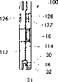
Fig. 1 is the cut-open view according to first embodiment of camera of the present invention;
Fig. 2 is the front portion cut-open view that the part of the actuator that uses among first embodiment that is illustrated in according to camera of the present invention is dissectd;
Fig. 3 is the cross-sectional view along the A-A line among Fig. 2, is illustrated in the actuator that uses among first embodiment according to camera of the present invention;
Fig. 4 is the phantom view on the top of the actuator that uses among the embodiment that is illustrated in according to camera of the present invention;
Fig. 5 A and Fig. 5 B are vertical view and the front elevations that drive coil, magnet, back side yoke (backyokes) is shown and attracts the part of the mutual alignment relation of yoke (attracting yokes) to amplify;
Fig. 6 and Fig. 7 A~7F be illustrate magnet move and by the figure of the relation between the signal that magnetic sensor produced;
Fig. 8 is the block diagram that the signal Processing on the controller is shown;
Fig. 9 is the figure that the drive coil that is installed on the fixed head is shown and is installed in the position relation of three magnet on the movable frame;
Figure 10 is the figure of the coil position command signal when being illustrated in translation and rotation movable frame;
Figure 11 illustrates Control current so that the circuit diagram of the example of the circuit of its inflow drive coil;
Figure 12 is the variation according to first embodiment of actuator of the present invention;
Figure 13 is another variation according to first embodiment of actuator of the present invention;
Figure 14 illustrates the front portion cut-open view that dissects according to the part of second embodiment of parallel movement apparatus of the present invention;
Figure 15 is the side sectional view that second embodiment of parallel movement apparatus is shown;
Figure 16 is the rear view that second embodiment of parallel movement apparatus is shown;
Figure 17 illustrates the front portion cut-open view that dissects according to the part of the 3rd embodiment of actuator of the present invention;
Figure 18 is the side sectional view that illustrates according to the 3rd embodiment of actuator of the present invention; And
Figure 19 is the rear view that illustrates according to the 3rd embodiment of actuator of the present invention.
Embodiment
The preferred embodiments of the present invention are described with reference to the accompanying drawings.
At first, describe first embodiment in detail with reference to figure 1~11 according to camera of the present invention.Fig. 1 is the cut-open view that illustrates according to first embodiment of camera of the present invention.
As can be seen from Figure 1, comprise lens unit 2 and camera body 4 by Reference numeral 1 represented first embodiment according to camera of the present invention.Lens unit 2 comprises: lens barrel 6, a plurality ofly be installed in taking lens 8 in the lens barrel 6, in predetermined plane mobile image stabilization camera lens 16 actuator 10 and be used separately as gyroscope (gyro) 34a, the 34b (Fig. 1 only illustrate gyroscope 34a) of vibration-sensing device with the vibration that detects lens barrel 6.Camera 1 uses gyroscope 34a, 34b to detect vibration, and in response to testing result, and actuator 10 work are with mobile image stabilization camera lens 16, thereby obtains to focus on the stabilized image on the film plane F in the camera body 4.Actuator 10 is made of parallel movement apparatus 11 combination driving devices that describe in detail the back.In this embodiment, gyroscope 34a, 34b use piezoelectric vibration gyroscope respectively.In addition, in this embodiment, image stabilization camera lens 16 is made of lens, and alternatively, it can be one group of lens more than lens.Below, in this manual, term " image stabilization camera lens " comprises and is used for lens and one group of lens of stabilized image.
Then, describe actuator 10 in detail with reference to figure 2~4.Fig. 2 is the front portion cut-open view of actuator 10, and Fig. 3 is the cross-sectional view along the A-A line among Fig. 2, and Fig. 4 is the cut-open view on its top.Fig. 2 is the diagram that the film plane F side from Fig. 1 is seen actuator 10, and the fixed head 12 that is partly dissectd is shown, and only the convenience in order to understand below is called " front elevation " with this view.Shown in Fig. 2~4, actuator 10 has: be fixed on fixed head 12 or fixed part in the lens barrel 6; The movable frame 14 or the movable part that are supported movably with respect to fixed head 12; And parallel movement apparatus 11, it comprises being sphere and three steel balls 18 that support movable frame 14 in shape.Parallel movement apparatus 11 has: magnet 30, as the spherical member suction device that steel ball 18 is attracted on the movable frame 14; Steel ball contact (contact) 31,31, it invests respectively on fixed head 12 and the movable frame 14, so that steel ball 18 smooth rolling between them.Three steel balls 18 are as the movable part bracing or strutting arrangement, and steel ball contact 31,32 provides the supporting plane of fixed part and movable part respectively simultaneously.
And, as shown in Figure 1, actuator 10 has control device or controller 36, and it controls the electric current that flows into drive coil 20a, 20b, 20c respectively according to the position data of the movable frame 14 that senses by the detected vibration of gyroscope 34a, 34b with by magnetic sensor 24a, 24b, 24c.
Be approximately columnar lens barrel 6 within it portion keep a plurality of taking lenss 8, and allow part taking lens 8 to move, thereby focus.
The shape approximation of fixed head 12 is circular, which is provided with three drive coil 20a, 20b, 20c.As can be seen from Figure 2, drive coil 20a, 20b, 20c are located on the circle identical with the optical axis of lens unit 2 of the center of circle.In this embodiment, drive coil 20a is positioned at the vertical direction of optical axis, and drive coil 20b is positioned at the horizontal level along optical axis, and drive coil 20c is positioned at respectively and spends the position of central angles with drive coil 20a and 20b at a distance of 135.Therefore, the adjacent windings 20a in the drive coil and 20b, 20b and 20c and 20c and 20a separate with 90 degree central angles, 135 degree central angles and 135 degree central angles respectively each other successively. Drive coil 20a, 20b, 20c have the winding (winding) of rounded square (rounded square) respectively, and these coils are configured such that the center line of its rounded square separately points to the radial direction of the circumference at coil place.
The shape approximation of movable frame 14 is circular, is positioned at the position that is parallel to fixed head 12 and covers this fixed head 12.In the center pit of movable frame 14, image stabilization camera lens 16 is installed.Square drive magnet 22 is embedded on the circumference of movable frame 14, and is located at the position corresponding to drive coil 20a, 20b, 20c respectively.In this manual, " corresponding to the position of drive coil " is meant the position that the magnetic field that produced by drive coil is substantially influenced.Each magnet 22 has rectangle back side yoke 28 at its reverse side, so that the magnetic flux of self-driven magnet 22 is set to expeditiously towards fixed head 12 in the future.
The reverse side of each drive coil on fixed head 12 promptly at the opposite side of movable frame 14, is installed rectangle and is attracted yoke 26.Owing to will be applied to from the magnetic force of each magnet 22 on the corresponding attraction yoke 26, thereby movable frame 14 is attracted on fixed head 12.In this embodiment, because fixed head 12 is formed by nonmagnetic substance, therefore arrive expeditiously and attract yoke 26 from the magnetic line of force of magnet 22.
Fig. 5 A is the vertical view that drive coil 20a, pairing magnet 22, back side yoke 28 is shown and attracts the part amplification of the position relation between the yoke 26, and Fig. 5 B is the front elevation that part is amplified.From Fig. 2 and Fig. 5 A and 5B as can be seen, be magnet 22, the back side yoke 28 of rectangle and attract yoke 26 to make its long limit separately, and its minor face is separately extended along minor face mutually mutually along the extension of long limit.In addition, drive coil 20a is so that its length limit and minor face are parallel to the long limit of corresponding rectangle back side yoke 28 and the mode of minor face is placed.Magnet 22 makes its each magnetic neutral axis C consistent with the radius of the circumference that magnet 22 is installed.Like this, when electric current flowed into corresponding drive coil, magnet 22 received the driving force of the tangential direction of circle.Remaining drive coil 20b, 20c with it each self-corresponding magnet 22, back side yoke 28 and the mode that attracts yoke 26 to have similar position relation arrange.In this manual, term " magnetic neutral axis C " is meant that connection is from being defined as the line of polarity magnet 22 opposite ends, that represent with the S utmost point and the N utmost point to the tr pt of another polarity.Therefore, in this embodiment, magnetic neutral axis C is through the mid point on the long limit of square drive magnet 22.In addition, shown in Fig. 5 A, magnet 22 also makes its polarity change on depth direction, supposes that lower-left and the upper right portion among Fig. 5 A is the South Pole (S), and the bottom right and upper left be the arctic (N).
As can be seen, drive coil 20a, 20b, 20c are respectively around magnetic sensor 24a, 24b, 24c from Fig. 2~5.When movable frame 14 therein during the property position, each magnetic sensor makes sensitivity center S be positioned at the magnetic neutral axis C of magnet 22.In this embodiment, Hall element is used for magnetic sensor.
Fig. 6 and Fig. 7 be the displacement of magnet 22 is shown and the signal that produced by magnetic sensor 24a between the figure of relation.As shown in Figure 6, when the magnetic neutral axis C that is positioned at magnet 22 as the sensitivity center of magnetic sensor 24a S goes up, be zero level from the output signal of magnetic sensor 24a.Along with the magnet 22 of movable frame on 14 along its moves and cause the sensitivity center S of magnetic sensor 24a to depart from the magnetic neutral axis, change from the output signal of magnetic sensor 24a.As shown in Figure 6, when when X-direction promptly moves magnet 22 perpendicular to the direction of magnetic neutral axis C, magnetic sensor 24a produces sinusoidal signal.Therefore, when displacement hour, magnetic sensor 24a produces the about proportional signal of displacement with magnet 22.In this embodiment, in the time of in the displacement of magnet 22 drops on less than 3% the scope on the long limit of magnet 22, be approximated to ratio from the signal of magnetic sensor 24a output and distance from the sensitivity center S of magnetic sensor 24a to magnetic neutral axis C.In addition, in this embodiment, as long as be approximated to ratio from the output of magnetic sensor with distance, actuator 10 can effectively be worked.
From Fig. 7 A~7C as can be seen, when the magnetic neutral axis C of magnet 22 is positioned at the sensitivity center S of magnetic sensor 24a, rotating or under the situation that Fig. 7 C magnet 22 moves along the direction of magnetic neutral axis C in Fig. 7 B magnet 22, is zero level from the output signal of magnetic sensor 24a.And, from Fig. 7 D~7F as can be seen, when the magnetic neutral axis C of magnet 22 departs from the sensitivity center S of magnetic sensor 24a, proportional from the signal and the following radius of a circle r of magnetic sensor 24a output: the center of this circle equals sensitivity center S, and tangent with the magnetic neutral axis C of magnet 22.Therefore, for with the same radius r of the tangent circle of the magnetic neutral axis C of magnet 22, moving, and along any direction translation in any case along direction, from the signal of magnetic sensor 24a generation same level as Fig. 7 F magnet 22 as 22 translations of Fig. 7 E magnet and rotation perpendicular to magnetic neutral axis C as Fig. 7 D magnet 22.
Although according to magnetic sensor 24a embodiment has been described at this, all the other magnetic sensor 24b, 24c with the position of corresponding magnet 22 relation under, also produce identical signal.Therefore, analyze the signal that is detected by magnetic sensor 24a, 24b, 24c respectively, can specify movable frame 14 position with respect to fixed head 12 after translation and rotational motion.
As can be seen from Figure 2, three steel balls 18 are set on the cylindrical that the circle with the drive coil that is provided with fixed head 12 separates.Steel ball 18 is separated from each other with the angle intervals of 120 degree central angles, and one of them steel ball 18 is arranged between drive coil 20a and the 20b.As shown in Figure 3, attract magnet 30, steel ball 18 is attracted on the movable frame 14 by the spheroid that embeds respectively on corresponding to the position of steel ball 18.Therefore, attract magnet 30 that steel ball 18 is attracted on the movable frame 14, by magnet 22 movable frame 14 is attracted on the fixed head 12 simultaneously, thereby steel ball 18 is clipped between fixed head 12 and the movable frame 14 by spheroid.This makes movable frame 14 supported in the plane that is parallel to fixed head 12, the rolling that remains on the steel ball 18 between these two parts allow movable frame 14 with any direction with respect to fixed head 12 translations and rotation.
And in this embodiment, steel ball contact 32 is made by nonmagnetic substance, so that come the magnetic flux of self-gravitation magnet 30 to arrive each steel ball 18 expeditiously.In addition, preferably, the thickness range of steel ball contact 31,32 is respectively from 0.2mm~0.5mm.In this embodiment, steel ball contact 31,32 is made by the thick aluminium of 0.3mm that has carried out the electroless nickel plating plating.In addition, in this embodiment, although steel ball 18 adopts the spheroid that is formed from steel, it needn't be spheroid.Therefore, steel ball 18 can replace with the substitute that any each surface in contact that makes itself and steel ball contact 32 is generally sphere.In this manual this form is called " pellet part ".
The control of actuator 10 is described with reference to figure 8 then.Fig. 8 is the block diagram that the system architecture of the signal Processing in the controller 36 is shown.As can be seen from Figure 8, by two gyroscope 34a, the 34b vibration of detector lens unit 2 constantly, and testing result is sent to lens location command signal generating apparatus or arithmetic circuity 38a, the 38b that is built in the controller 36.In this embodiment, gyroscope 34a is suitable for the angular acceleration of the yaw motion of sensing lens unit 2, and gyroscope 34b is suitable for the angular acceleration of the luffing of sensing lens unit.
From gyroscope 34a, 34b constantly during the acceptance angle acceleration, arithmetic circuity 38a, 38b produce the command signal that indicating image is stablized the time dependent position that camera lens 16 moves to.Particularly, arithmetic circuity 38a angular acceleration to the yaw motion that detected by gyroscope 34a in time integral is handled carries out integration twice, and add that predetermined correction signal is to obtain the horizontal component of lens location command signal, similarly, arithmetic circuity 38b carries out arithmetical operation by the angular acceleration to the luffing that detected by gyroscope 34b, produces the vertical component of lens location command signal.Thus obtained lens location command signal is used for changing in time the mobile image stabilization camera lens 16 in ground, even so that when lens unit between the exposure period of taking pictures 2 vibration, and the image shake that focuses on the film plane F in camera body 4 but stablize.
The coil position command signal generation device that is built in the controller 36 is suitable for producing and each drive coil associated coil position command signal based on the lens location command signal that is generated by arithmetic circuity 38a, 38b.The coil position command signal is to move under the situation of the position of being indicated by the lens location command signal at image stabilization camera lens 16, the signal of the position relation between expression drive coil 20a, 20b, 20c and the self-corresponding magnet 22 of Qi Ge.Particularly, when magnet 22 and its drive coil separately were moved to the position of being indicated by the coil position command signal in pairs, image stabilization camera lens 16 was moved to the position that is moved to by the indication of lens location command signal.In this embodiment, because drive coil 20a in the vertical direction of optical axis, therefore equates with the horizontal component of drive coil 20a associated coil position command signal with the lens location command signal that produces from arithmetic circuity 38a.In addition, because drive coil 20b is positioned at the side of optical axis, therefore equate with the vertical component of drive coil 20b associated coil position command signal with the lens location command signal that produces from arithmetic circuity 38b.And, based on the level and the vertical component of lens location command signal, produce and drive coil 20c associated coil position command signal from coil position command signal generation device or arithmetic circuity 40.
On the other hand, amplify the displacement of the magnet 22 judged by magnetic sensor 24a with predetermined enlargement factor by magnetic sensor amplifier 42a with respect to drive coil 20a.Differential circuit 44a allows electric current to flow into drive coil 20a with following ratio: this ratio and from the horizontal component of the coil position command signal of arithmetic circuity 38a and proportional from the difference between 42a's and the paired magnet 22 of drive coil 20a the displacement of magnetic sensor amplifier.Therefore, when being zero when the coil position command signal with from the difference between the output of magnetic sensor amplifier 42a, do not have electric current to flow into drive coil 20a, the power that causes driving magnet 22 also is zero.
Similarly, amplify the displacement of the magnet 22 judged by magnetic sensor 24b with predetermined enlargement factor by magnetic sensor amplifier 42b with respect to drive coil 20b.Differential circuit 44b allows electric current to flow into drive coil 20b with following ratio: this ratio and from the vertical component of the coil position command signal of arithmetic circuity 38b and proportional from the difference between 42b's and the paired magnet 22 of drive coil 20b the displacement of magnetic sensor amplifier.Therefore, when being zero when the coil position command signal with from the difference between the output of magnetic sensor amplifier 42b, do not have electric current to flow into drive coil 20b, the power that causes driving magnet 22 also is zero.
Similarly, amplify the displacement of the magnet 22 judged by magnetic sensor 24c with predetermined enlargement factor by magnetic sensor amplifier 42c with respect to drive coil 20c.Differential circuit 44c allows electric current to flow into drive coil 20c with following ratio: this ratio and from the coil position command signal of arithmetic circuity 40 and proportional from the difference between 42c's and the paired magnet 22 of drive coil 20c the displacement of magnetic sensor amplifier.Therefore, when being zero when the coil position command signal with from the difference between the output of magnetic sensor amplifier 42c, do not have electric current to flow into drive coil 20c, the power that causes driving magnet 22 also is zero.
With reference to figure 9, the relation of lens location command signal and coil position command signal under the situation of translation movable frame 14 will be described now.Fig. 9 is the figure that drive coil 20a, 20b, the 20c that is located on the fixed head 12 is shown and is configured in the position relation of three magnet 22 on the movable frame 14.At first, to lay respectively at radius be L, M, N point on the circle consistent with initial point (or zero point) Q of coordinate system of R, center for three drive coil 20a, 20b, 20c. Magnetic sensor 24a, 24b, 24c also be positioned at make its sensitivity center S separately respectively with a L, M, N consistent location.When movable frame 14 is positioned at neutral position, perhaps when the center of image stabilization camera lens 16 is on optical axis, also consistent with a L, M, N respectively with the mid point of the magnetic neutral axis C of the paired magnet 22 of drive coil.Suppose that transverse axis X and Z-axis Y with common initial point Q intersect with another V with 135 degree at initial point respectively, magnet makes its magnetic neutral axis C separately consistent with X-axis, Y-axis and V axle respectively.
Then, when mobile movable frame 14 so that the center of image stabilization camera lens 16 moves to a Q
1, and further about a Q
1During move angle θ, the mid point of the magnetic neutral axis C of magnet 22 is moved to a L respectively in the counterclockwise direction
1, M
1, N
1For movable frame 14 is moved to this position, need make its signal level separately proportional with following radius of a circle respectively with drive coil 20a, 20b, 20c associated coil position command signal: these circles make its center separately consistent with a L, M, N respectively, and respectively with straight line Q
1L
1, Q
1M
1, Q
1N
1Tangent.These radiuses of this circle are respectively by r
X, r
Y, r
VRepresent.
Judge coil position command signal r as shown in Figure 9
X, r
Y, r
VPositive and negative condition.Particularly, will put L
1Move to the coil position command signal r of first quartile
XFor just, move to second quadrant then for negative; Similarly, will put M
1Move to the command signal r of first quartile
YFor just, move to four-quadrant then for negative.In addition, will put N
1Move to the following coil position order r of V axle
VJust be judged as, move to more than the V axle then for negative.For the positive and negative condition of angle, making clockwise direction is positive sign.Therefore, if movable frame 14 rotates along clockwise direction from neutral position, coil position command signal r then
X, r
Y, r
VBe assumed to positive and negative and negative respectively.
In addition, present assumed position Q
1, L
1, N
1Coordinate be respectively (j, g), (i, e) and (k, h), and V axle and Y-axis intersect at the angle [alpha] place.And supposition has process point M and is parallel to straight line Q
1L
1Boost line A with through some L and be parallel to straight line Q
1M
1The intersection point P of another boost line B.
Now right-angle triangle LMP is used sine, provides following equation:

Obtain following formula from above equation:
LP=R(cosθ+sinθ) (2)
MP=R(cosθ-sinθ) (3)
Use R, a r
X, r
Y, r
V, θ and α come that denotation coordination e, g, h, i, j and k are as follows respectively:
e=-r
Xsinθ+R
g=e-( MP-r
Y)cosθ=-r
Xsinθ+r
Ycosθ-Rcosθ(cosθ-sinθ)+R
h=-Rcosα-r
Vsin(α+θ)
i=r
Xcosθ (4)
j=i-( MP-r
Y)sinθ=r
Xcosθ+r
Ysinθ-Rsinθ(cosθ-sinθ)
k=-Rsinα+r
Vcos(α+θ)
For have apex coordinate for (k, g), (j, g) and (k, right-angle triangle h) can be represented the relation set up in order to following equation:
Above equation (5) can launch and be rearranged as following equation:
r
Xcosα-r
Ysinα-r
V=R(sinα+cosα)sinθ+Rsinθ (6)
In addition, under the situation of translation movable frame 14, satisfy θ=0, and reorganize above equation (6) as follows:
r
Xcosα-r
Ysinα-r
V=0 (7)
In this embodiment, also satisfy α=45 °, then formula (7) can be simplified as follows:
Therefore, in this embodiment, (j is in the time of g), for drive coil 20a and 20b generate coil position command signal r respectively when image stabilization camera lens 16 makes its center move to coordinate in response to the lens location command signal
XAnd r
Y, signal level and coordinate j and g separately is proportional for these command signals, simultaneously, calculates the coil position command signal r of drive coil 20c by application of formula (8)
V
Coil position command signal r
XWith identical from the output signal of the arithmetic circuity 38a among Fig. 8, and coil position command signal r
YWith identical from the output signal of arithmetic circuity 38b.Similarly, coil position command signal r
VWith identical from the output signal of arithmetic circuity 40, this arithmetic circuity 40 is provided by the identical arithmetical operation of processing that provides with formula (8).
Then, with reference to Figure 10, promptly rotating under the situation of movable frame 14 relation of lens location command signal and coil position command signal.Figure 10 is illustrated in translation and rotates under the situation of movable frame 14 figure of coil position command signal.As can be seen from Figure 10, at first translation movable frame 14 moves to another Q so that be installed in the center of the image stabilization camera lens 16 on the movable frame 14 from a Q
2, therefore, the magnet 22 that is installed on the movable frame 14 is moved to a L from a L, M, N respectively
2, M
2, N
2For this translation motion, produce coil position command signal r
X, r
Y, r
VCan obtain the signal level of coil position command signal by above-mentioned equation (8).At movable frame 14 about a Q
2Under the situation of counter clockwise direction rotational angle η, will obtain command signal r
X η, r
Y η, r
V η
Identical with situation shown in Figure 9, assumed position Q at first
2Coordinate and straight line Q
2N
2With radius be r
V, the center be the coordinate at point of contact of the circle of N be respectively (j, g) and (k, h), and with the zero item θ that replaces in the equation (4), derive following the relation:
g=r
Y
j=i=r
X (9)
When movable frame 14 about a Q
2In the counterclockwise direction during rotational angle η, some L
2, M
2, N
2Move to a L respectively
3, M
3, N
3Also be presumed to right line segment Q
2L
2And Q
2L, Q
2M
2And Q
2M and Q
2N
2And Q
2The angle of N is represented with β, δ and γ respectively.In addition, suppose line segment Q
2L, Q
2M and Q
2N lengths table separately is shown U, W and V.Coil position command signal r
X η, r
Y η, r
V ηSignal level separately equal respectively separately the center for some L, a M, N and with straight line Q
2L
3, Q
2M
3, and Q
2N
3Tangent radius of a circle, therefore, can set up the relation of following expression:
r
Xη=Usin(β+η)=U(sinβcosη+cosβsinη)
r
Yη=-Vsin(γ+η)=-V(sinγcosη+cosγsinη) (10)
r
Yη=-Wsin(δ+η)=-W(sinδcosη+cosδsinη)
According to some mathematical relations, can replace sin β, cos β and other with following formula:
In addition, come the item of each correspondence in the replacement formula (10) with the relation in the formula (11), with eliminate as β, γ and δ, thereby obtain representing the formula of following relation:
r
Xη=r
Xcosη+(R-r
Y)sinη
r
Yη=r
Ycosη-(R-r
X)sinη
Therefore, for movable frame 14 being moved to by at first the center of image stabilization camera lens 16 being moved to coordinate (j, g), in the counterclockwise direction its rotational angle η on definite point, is at first obtained coil position command signal r by formula (8) and (9) about resulting point then
X, r
Y, r
V, use the respective items in the value replacement formula (12) that is obtained then, with the coil position command signal r that obtains drive coil is provided
X η, r
Y η, r
V η
There is not translation motion at movable frame 14, and about a Q in the counterclockwise direction under the situation of rotational angle η, the r in week zero replacement formula (12)
X, r
Y, r
VItem is as follows:
r
Xη=Rsinη
r
Vη=Rsinη (13)
r
Yη=-Rsinη
Therefore, can obtain coil position command signal r by arithmetical operation
X η, r
Y η, and r
V η
Then, with reference to Figure 11, the exemplary circuit of controller 36 is described.Figure 11 illustrates the example of the circuit of controlling the electric current that flows into drive coil 20a.In the circuit of Figure 11, the auxiliary circuit of omission startup operational amplifier is power lead for example.At first, as can be seen from Figure 11, supply voltage+V
CCLink together with ground and resistance R 7 and R8.The positive input terminal of operational amplifier OP4 is connected between resistance R 7 and the R8.The negative input end of operational amplifier OP4 is connected to the output terminal of operational amplifier OP4.Like this, resistance R 7 and R8 allow the voltage of the output terminal of operational amplifier OP4 to reach supply voltage V
CCAnd the reference voltage V between the ground potential GND
REFLevel so that it can keep this level.
On the other hand, between first and second terminals of magnetic sensor 24a, apply supply voltage+V
CCThe 3rd terminal of magnetic sensor 24a is connected to reference voltage V
REFLike this, because the magnetic force that influences magnetic sensor 24a changes, thereby the 4th terminal of magnetic sensor 24a is correspondingly at+V
CCAnd change between the GND.
The 4th terminal of magnetic sensor 24a is connected to the negative input end of operational amplifier OP1, inserts variable resistor VR2 between wherein, and can adjust from the output gain of magnetic sensor 24a by regulating variable resistor VR2.The relative fixed end of variable resistor VR1 is connected respectively to+V
CCVoltage level with GND.The convertible tip of variable resistor VR1 is connected to the negative input end of operational amplifier OP1, wherein inserts resistance R 1.Can adjust from the bucking voltage of operational amplifier OP1 output by regulating variable resistor VR1.In addition, the positive input terminal of operational amplifier OP1 is connected to reference voltage V
REFThe output terminal of operational amplifier OP1 is connected to the negative input end of operational amplifier OP1, wherein inserts resistance R 2.
The arithmetic circuity 38a that produces the coil position command signal relevant with drive coil 20a is connected to the positive input terminal of operational amplifier OP3.Operational amplifier OP3 makes its output terminal be connected to the negative input end of operational amplifier OP3.Therefore, operational amplifier OP3 is as the buffer amplifier of coil position command signal.
The output terminal of operational amplifier OP1 is connected to the negative input end of operational amplifier OP2, wherein inserts resistance R 3.In addition, the output terminal of operational amplifier OP3 is connected to the positive input terminal of operational amplifier OP2, wherein inserts resistance R 4.Like this, produce poor from the output of magnetic sensor 24a and coil position command signal from the output terminal of operational amplifier OP2.Operational amplifier OP2 makes its positive input terminal be connected to reference voltage V
REF, wherein insert resistance R 5, and make its output terminal be connected to the negative input end of operational amplifier OP2, wherein insert resistance R 6.Define the positive and negative output gain of operational amplifier OP2 by these resistance R 5 and R6.
Operational amplifier OP2 makes its output terminal be connected to one of them opposite end of drive coil 20a, and the other end of drive coil 20a is connected to reference voltage V
REFTherefore, with output and reference voltage V from operational amplifier OP2
REFBetween the electric current that equates of voltage difference flow into drive coil 20a.The electric current that flows into drive coil 20a produces magnetic field, and makes magnetic force influence magnet 22, finally produces the displacement of magnet 22.This magnetic force is used for making magnet 22 near the indicated position of coil position command signal.In case mobile magnet 22, then the voltage of exporting from the 4th terminal of magnetic sensor 24a changes.When magnet 22 arrived the indicated position of coil position command signals, the voltage that provides to the positive and negative input end of operational amplifier OP2 became and is equal to each other, and no longer includes electric current and flows into drive coil 20a.
Operational amplifier OP1 among above-mentioned Figure 11 is corresponding with magnetic sensor amplifier 42a and differential circuit 44a among Fig. 8 with OP2.Flow into the circuit of drive coil 22a although Control current has been described, the electric current that flows into drive coil 20b is also controlled by same circuit.In addition, the electric current that flows into drive coil 20c can be controlled by same circuit, but in this case, arithmetic circuity 40 makes its output be connected to the positive input terminal of operational amplifier OP3.Arithmetic circuity 40 comprises the function differential amplifier identical with operational amplifier OP2, (1/2) that produces the pre-service level
1/2The resistance etc. of dividing potential drop.
With reference to figure 1 and 8, with the operation of explanation according to first embodiment of camera 1 of the present invention.At first, connect the starting switch (not shown) of the anti-vibration functions of camera 1, allow the actuator 10 in the lens unit 2 to start working.Be built in gyroscope 34a in the lens unit 2 and 34b and detect vibration in time with changing at predetermined frequency band, and gyroscope 34a is to the angular acceleration signal of arithmetic circuity 38a generation yawing moment, and gyroscope 34b produces the angular acceleration signal of pitch orientation simultaneously.Arithmetic circuity 38a carries out twice integration calculating deflection angle to the angular acceleration signal that receives in time integral is handled, and with result of calculation further with predetermined correction signal addition, with the command signal of the lens location that produces horizontal direction.Equally, arithmetic circuity 38b carries out twice integration calculating luffing angle to the angular acceleration signal that receives in time integral is handled, and with result of calculation and predetermined correction signal addition, with the command signal of the lens location that produces vertical direction.On time dependent basis, image stabilization camera lens 16 is moved to the indicated position of lens location command signal that is produced from arithmetic circuity 38a, 38b in time with changing, thereby can stablize the image on the film plane F that focuses in the camera body 4.
The command signal of the lens location of the horizontal direction that will be produced from arithmetic circuity 38a is sent to differential circuit 44a, as with drive coil 20a associated coil position command signal r
XEqually, the command signal of the lens location of the vertical direction that will produce from arithmetic circuity 38b is sent to differential circuit 44b, as with drive coil 20b associated coil position command signal r
YOutput from arithmetic circuity 38a, 38b is sent to arithmetic circuity 40, and the represented arithmetical operation of formula (8) can produce the coil position command signal r to drive coil 20c
V
On the other hand, lay respectively at that magnetic sensor 24a, the 24b of drive coil 20a, 20b and 20c inside and 24c are respectively magnetic sensor amplifier 42a, 42b and 42c generates detection signal.After being amplified respectively in magnetic sensor amplifier 42a, 42b and 42c by detection signal that magnetic sensor detected, be sent to differential circuit 44a, 44b and 44c respectively.
Differential circuit 44a, 44b and 44c produce respectively with from the received detection signal and the coil position command signal r of magnetic sensor
X, r
Y, and r
VBetween the voltage that equates of difference, and allow and the proportional electric current of this voltage flows into drive coil 20a, 20b and 20c respectively.When electric current flows into drive coil, produce and the proportional magnetic field of this electric current.Because this magnetic field makes the magnet 22 that is installed in the drive coil correspondence position respectively to more close coil position command signal r
X, r
Y, and r
VMove indicated position.When magnet 22 during by drive force, the steel ball 18 between movable frame 14 and the fixed head 12 rolls, so that keep movable frame 14 smooth moving in predetermined plane of magnet 22.Simultaneously, because steel ball 18 rolls on steel ball contact 31,32, the mobile resistance that causes by movable frame 14 only is the resistance to rolling of rolling at surface in contact from steel ball, therefore, do not having under the situation of sliding-frictional resistance, movable frame 14 can come smooth moving by minimum as far as possible driving force.In addition, steel ball 18 and steel ball contact 31,32 are made by the material with high surface hardness, and therefore, the resistance to rolling between steel ball 18 and the steel ball contact 31,32 is significantly reduced.
Change ground in time and repeat above-mentioned steps, the image stabilization camera lens 16 that allows to be installed on the movable frame 14 arrives specified position with magnet 22 with the lens location command signal.Therefore, the image on the stable film plane F that focuses in the camera body 4.
In first embodiment, because the movable frame of image stabilization actuator can move along desired direction, and do not use quadrature guide member, so actuator can have simple structure two different directions guiding according to camera of the present invention.In addition, in this embodiment, the movable frame of image stabilization actuator can be along desired direction translation and rotation in predetermined plane.
And, in first embodiment according to camera of the present invention, because the movable frame of the parallel movement apparatus that is provided in the actuator is supported by steel ball, so moving of movable frame do not produce sliding-frictional resistance substantially, and little driving force just is enough to make, and movable frame is smooth moves.And this simple structure advantageously makes the weight saving of the movable frame of parallel movement apparatus, and this also makes the just mobile movable frame of energy of little driving force, thus the final actuator of response fast that obtains.
Although the first embodiment of the present invention has been described, can carry out various modifications to it.Especially, the present invention is used for roll film camera in the above-described embodiments, but it can be used for any frequency still camera or animated photography machine, comprises digital camera, video camera etc.In addition, the lens unit that uses applicable to camera body of the present invention with any above-mentioned camera.In addition, the present invention can be used as the parallel movement apparatus of the image stabilization camera lens of mobile cameras, perhaps moving meter any other parallel movement apparatus of XY platform (stage) etc. for example.
In addition, in above-mentioned first embodiment, because the spherical member that is installed on the movable frame attracts magnet, steel ball attracted on the movable frame, but alternatively, spherical member attracts magnet can be installed on the fixed head, and steel ball attracted on the fixed head simultaneously.
And in above-mentioned first embodiment, although spherical member or steel ball attracted on the movable frame by magnetic force, alternatively, spherical member can attracted in movable frame or the fixed head any by electrostatic force or any other power.
In addition, in above-mentioned first embodiment, three spherical members or steel ball support movable frame with respect to fixed head, but replace, and available four or more a plurality of spherical member support movable frame.
In addition, in above-mentioned first embodiment, drive coil is installed on the fixed part, and magnet is installed on the movable part, and on the contrary, magnet can be installed in fixed part, and drive coil is installed in movable part.In addition, in above-mentioned first embodiment, use three pairs of drive coils and magnet, alternatively, can use four pairs or how right drive coil and magnet.In addition, in above-mentioned first embodiment, permanent magnet is used as magnet, but to its also optional electromagnet of using.
In above-mentioned first embodiment, magnetic sensor is used as position detecting device with the magnetic force of detection from magnet, and judges its position separately, alternatively, except that magnetic sensor, replaceablely detect the relative position of magnet to drive coil for any position-detection sensor.
In addition, in above-mentioned first embodiment, drive coil is by following layout: make drive coil to 24a and 24b, 24c and 24a, and 24b and 24c respectively with 90 degree, 135 degree, and 135 degree central angles intersect, and alternatively, can determine drive coil 24c the position so that the central angle at the intersection point place of drive coil 24b and drive coil 24c in the represented scope of formula 90+ α (0≤α≤90).In addition, the central angle at the intersection point place of drive coil 24a and 24b can be any desired angle except 90 degree, and the central angle scope that three drive coils intersect can be spent to 180 degree for 90, and for example whole three central angles that are made of three drive coils are 120 degree.
And in above-mentioned first embodiment, the magnetic neutral axis of magnet all radially extends, and alternatively, it can be towards any desired direction.Preferably, at least one magnet is arranged to its magnetic neutral axis and radially extends.
Figure 12 illustrates the variation to above-mentioned first embodiment of the present invention, wherein extend to the tangent line of center with the magnetic neutral axis of the paired magnet 22 of drive coil 24a and 24b respectively, and as one man extend with magnetic neutral line and this radius of a circle of the magnet 22 of the paired remainder of drive coil 24c for the circle of some Q.Although omit in the drawings, drive coil 24a, 24b, 24c lay respectively at a L, M, N.In this embodiment, produce and drive coil 24a, 24b, coil position command signal r that 24c is relevant
X, r
Y, and r
VTo indicate these magnets from its current location L, M separately, the position that N moves to.Because the coil position command signal is positioned at movable frame 14 under the situation of its neutral position, the mid point of the magnetic neutral axis of the magnet 22 at some L, M, N place is moved on to L respectively
4, M
4, N
4, simultaneously, the center of image stabilization camera lens 16 is moved on to a Q from a Q
3
In this variation, with coil position command signal r
X, promptly the horizontal component of lens location command signal offers the drive coil 24b at a M place, and with coil position command signal r
Y, promptly the vertical component of lens location command signal offers the drive coil 24a at a L place.In addition, under situation shown in Figure 12, with coil position command signal r
XAnd r
YReplace with the respective items in the formula (8), provide thus obtained and drive coil 24c associated coil position command signal r
V, the result makes a Q respectively along X-axis and Y-axis translation-r
XWith+r
Y
Then, with reference to Figure 13, another variation according to above-mentioned first embodiment of the present invention is described.This embodiment is different from the foregoing description part and is, when need not to control movable frame 14, actuator 45 has movable frame 14 is fixed on locking mechanism on the fixed head 12.
As can be seen from Figure 13, actuator 45 in this embodiment has three copulational protuberance 14a in the periphery of movable frame 14.Fixed head 12 also has the annular element 46 around movable frame 14, and this annular element 46 Zhou Yousan joint element 46a within it, to match with copulational protuberance 14a respectively.In addition, movable frame 14 has three movable parts maintenance magnets 48 in its periphery.Annular element 46 keeps having three fixed heads on the position of magnet 48 and keeps magnets 50 corresponding to movable part in interior week, so that these two groups of magnets produce magnetic force and influence each other on man-to-man basis.And manual locking element 52 extends along radial direction inwards from the outside of annular element 46, and can move along the circumferencial direction of annular element 46.The top of manual locking element 52 is processed as U-shaped groove 52a.Double pointed nail 54 is positioned at the periphery of movable frame 14, so that it is contained among the U-shaped groove 52a, and engages with manual locking element 52.
The operation of actuator 45 will be described in detail.At first, in Figure 13, the movable frame of actuator 45 rotates in the counterclockwise direction, thereby the copulational protuberance 14a of the periphery of movable frame 14 engages with joint element 46a in the annular element 46 respectively, thereby movable frame 14 is fixed on the fixed head 12.In addition, the movable part on movable frame 14 keeps the fixed part in magnet 48 and the annular element 46 to keep magnet 50 to influence each other hardly under situation shown in Figure 13.When movable frame 14 rotates in the counterclockwise direction, and when carrying movable part and keeping magnet 48 more close fixed parts to keep magnet 50, fixed part keeps 50 pairs of movable frames 14 of magnet to apply magnetic force so that it rotates along clockwise direction.Repel each other with magnetic force, movable frame 14 further rotates in the counterclockwise direction, keeps magnet 48 to keep magnet 50 through fixed part up to movable part, and therefore, fixed part keeps 50 pairs of movable frames 14 of magnet to apply magnetic force so that it rotates in the counterclockwise direction.This magnetic force forces copulational protuberance 14a crimping joint element 46a, and therefore, copulational protuberance 14a and joint element 46a keep cooperatively interacting.Like this, during the power supply supply that stops actuator 45, guarantee the stable engagement of copulational protuberance 14a and joint element 46a, movable frame 14 is fixed on the fixed head 12.
When manual locking element 52 among Figure 13 in the counterclockwise direction during hand rotation, the double pointed nail 54 on the movable frame 14 is hooked among the U-shaped groove 52a, and movable frame 14 also rotates in the counterclockwise direction.Like this, copulational protuberance 14a and joint element 46a can manually interconnect.When manual locking element 54 oppositely or along clockwise direction during hand rotation, movable frame 14 rotates along clockwise direction, and this makes copulational protuberance 14a and joint element 46a be separated from each other.
Actuator among this embodiment can rotate movable frame, and as this variation, realizes this locking mechanism easily.
Now, with reference to Figure 14~16 second embodiment according to parallel movement apparatus of the present invention is described.Except the equality unit that does not have the drive unit of employed actuator in the camera of first embodiment, parallel movement apparatus of the present invention almost with first embodiment in identical.Therefore, below the different assembly of assembly among explanation and first embodiment only, and identical Reference numeral represents identical assembly, and omits its explanation.
Figure 14,15 and 16 is front portion cut-open view, side sectional view and rear views that parallel movement apparatus 100 is shown respectively.Figure 14 illustrates the parallel movement apparatus of seeing from fixed head 112 sides 100, and the fixed head 112 that is partly dissectd is shown, and only the convenience in order to understand below is called " front elevation " with this view.
Shown in Figure 14~16, parallel movement apparatus 100 has: fixed head 112 or fixed part; The movable frame 114 or the movable part that are supported movably with respect to fixed head 112; And support movable frame 114 is three steel balls 18 of spherical member.Movable frame 114 has the image stabilization camera lens 16 that is installed in its center.Parallel movement apparatus 100 also comprises: attract the steel ball of steel ball 18 to attract magnet 30; Be installed in the steel ball contact 31,32 on fixed head 112 and the movable frame 114 respectively.In addition, parallel movement apparatus 100 also has: three keep magnet 122; Be installed in three the corresponding attraction yokes 126 of the position with keeping magnet 122 on the fixed head 112; And be installed in the reverse side that keeps magnet 122 respectively, make the magnetic flux that keeps magnet effectively propagate into three back side yokes 128 of corresponding attraction yoke 126.Keep magnet 122, attract yoke 126 and back side yoke 128 collaborative work together, as the movable part suction device.
Keep magnet 122, attract yoke 126 and back side yoke 128 to be separately positioned on the circle of first on fixed head 112 and the movable frame 114, be separated from each other with 120 intervals of spending central angles.Keeping magnet 122, attracting yoke 126 and back side yoke 128 is rectangular slab, and its shape and size all are similar to identical, makes its each long limit parallel with the tangent line of first circle.As can be seen from Figure 15, keep magnet 122, attraction yoke 126 and back side yoke 128 overlapped, therefore, back side yoke 128 is used for making the magnetic flux of self-sustaining magnet 122 effectively to propagate into attraction yoke 126, thereby movable frame 114 can be attracted on the fixed head 112.
Three spherical members attract magnet 30 to be set on the movable frame 114, and the angle intervals with 120 degree central angles on second circle outside first circle is separated from each other.And as can be seen from Figure 16, three spherical members attract magnet 30 respectively on the mid point between a pair of adjacent maintenance magnet 122, from equal angular at interval and the maintenance magnet 122 that is provided with 60 degree central angles separately.Three steel balls 18 are attracted magnet 30 to attract by spherical member, and are set at the position at these magnet places.Spherical member attracts magnet 30 to allow steel ball 18 to attracted on the movable frame 114, and movable frame 114 attracted on the fixed head 112 by the magnetic flux that comes self-sustaining magnet 122 simultaneously, and therefore, steel ball 18 is sandwiched between movable frame 114 and the fixed head 112.
When reality was used parallel movement apparatus in the second embodiment of the present invention, drive unit applied driving force to movable frame 114 arbitrarily, so that it moves in the plane that is parallel to fixed head 112.Simultaneously, the steel ball 18 that rolls on steel ball contact 31,32 can move movable frame 114 with respect to fixed head 112.Because movable frame 114 is supported by three steel balls 18, therefore, only the resistance to rolling from steel ball 18 influences movable frame 114 a little, and does not almost have the influence of sliding-frictional resistance.
In second embodiment according to parallel movement apparatus of the present invention, for the frictional resistance that does not almost have slip that moves of movable frame, therefore, little driving force just is enough to movable frame is moved.
Now, with reference to Figure 17~19 another embodiment according to actuator of the present invention, i.e. the 3rd embodiment are described.Except that the elasticity of flexible member can be attracted to movable frame on the fixed head, this embodiment of actuator was almost identical with the actuator that uses in the camera of first embodiment.Therefore, below the different assembly of assembly among explanation and first embodiment only, and identical Reference numeral represents identical assembly, and omits its explanation.
Figure 17,18 and 19 is front portion cut-open view, side sectional view and rear views that actuator 200 is shown respectively.Figure 17 illustrates the actuator of seeing near fixed head 112 sides of partly being dissectd 200, below this view is called " front elevation ".
Shown in Figure 17~19, actuator 200 has: fixed head 212 or fixed part; Load image is stablized the movable frame 214 or the movable part of camera lens 16 movably; And be three steel balls 18 of spherical member.Actuator 200 also comprises: as the magnet 30 of spherical member suction device; Be installed in the steel ball contact 31,32 on fixed head 212 and the movable frame 214 respectively.Three steel balls 18 are together as the movable part bracing or strutting arrangement, and steel ball contact 31,32 constitutes the supporting plane of fixed part and movable part respectively simultaneously.
As shown in figure 17, steel ball 18 is set on the cylindrical of circle at the drive coil place on the fixed head 12.Three steel balls 18 are separated from each other with the angle intervals of 120 degree central angles, the adjacent driven coil between mid point on.As shown in figure 18, attract magnet 30, steel ball 18 is attracted on the movable frame 214 by being embedded on the movable frame 214 with spherical member with the location overlap of steel ball 18.Steel ball 18 is sandwiched between movable frame 214 and the fixed head 212.Like this, movable frame 214 is maintained on the plane that is parallel to fixed head 212, and the rolling of steel ball 18 between these two parts allow movable frame 214 with any direction with respect to fixed head 212 translations and rotation.
In addition, annular steel ball contact 31,32 lays respectively at the periphery of fixed head 212 and movable frame 214, to contact with steel ball 18.Under steel ball 18 is sandwiched in situation between fixed head 212 and the movable frame 214, if mobile movable frame 214 will cause that then steel ball 18 rolls between steel ball contact 31,32.Therefore, when movable frame 214 moves with respect to fixed head 212, can not produce sliding friction between them.
The shape approximation of fixed head 212 is circular or discoid, and provide with fixed head concentric be almost circular fixed head substrate 230.Similarly, it is circular or discoid that the shape of movable frame 214 also is approximately, and be installed on the movable frame with the concentric circular movable frame substrate 234 that is almost of movable frame 214.As shown in figure 18, on the circle of fixed head 212 and movable frame 214, provide three couples of through hole 212a, 214a with 120 angle intervals of spending central angles, and through hole 212a, 214a align mutually to become one fully.In through hole 212a, the 214a that becomes one, provide spring 232.
Each spring 232 makes the straight line extension vertically of one end, and the other end bends to hook.With the rectilinear end of each spring 232 insert be positioned at fixed head substrate 230 on the aperture of each corresponding position of through hole 212a, and be soldered in the fixed head substrate 230.On the other hand, the end that spring 232 has a hook hooks by being positioned at the pawl 234a that the position corresponding with each through hole 214a in the movable frame substrate 234 form, and is soldered in the movable frame substrate 234.Each spring 232 has an end of hook to be stretched, and is hooked by pawl 234a then, and therefore, movable frame 214 is pulled to fixed head 212 by the elastic force of spring 232, as it is attracted on the fixed head.Like this, steel ball 18 is sandwiched between fixed head 212 and the movable frame 214.Through hole is enough big to 212a, 214a size, and when not surpassing its actual usable range with convenient movable frame 214 with respect to fixed head 212 translations, spring 232 can not run into the inwall of every couple of through hole 212a, 214a.In addition, being installed in movable frame substrate 234 on the movable frame 214 and the fixed head substrate 230 that is installed on the fixed head 212 interconnects by spring 232, therefore, spring 232 also can be used as the conductor that transmits the electric signal between fixed head substrate 230 and the movable frame substrate 234.
Except movable frame 214 be attracted on the fixed head 212 by spring 232 and, identical according to the operation of the actuator 10 that uses in the operation of the 3rd embodiment of actuator 200 of the present invention and the first embodiment of the present invention, therefore, omit its detailed description.
Utilization produces frictional resistance according to the actuator of third embodiment of the invention hardly for moving of movable frame, and therefore, little driving force just is enough to movable frame is moved.
Being simply described as follows of symbol in the accompanying drawing:
1 camera
2 lens units
4 camera bodies
6 lens barrels
8 taking lens
10 actuators
11 parallel movement apparatus
12 fixed heads
14 removable plates
16 image stabilization camera lenses
18 steel balls
The 20a drive coil
The 20b drive coil
The 20c drive coil
22 magnet
The 24a magnetic sensor
The 24b magnetic sensor
The 24c magnetic sensor
26 attract yoke
28 back side yokes
30 steel balls attract magnet
31 steel ball contacts
32 steel ball contacts
The 34a gyroscope
The 34b gyroscope
36 controllers
The 38a arithmetic circuity
The 38b arithmetic circuity
40 arithmetic circuities
42a magnetic sensor amplifier
42b magnetic sensor amplifier
42c magnetic sensor amplifier
The 44a differential amplifier
The 44b differential amplifier
The 44c differential amplifier
The actuator of 45 variation
46 annular elements
The 46a joint element
48 movable parts keep magnet
50 fixed parts keep magnet
52 manual stop components
52a U-shaped groove
54 double pointed nails
100 parallel movement apparatus
112 fixed heads
114 movable frames
122 keep magnet
126 attract yoke
128 back side yokes
200 actuators
212 fixed heads
214 movable frames
The 220a drive coil
The 220b drive coil
The 220c drive coil
222 magnet
The 224a magnetic sensor
The 224b magnetic sensor
The 224c magnetic sensor
228 back side yokes
230 fixed head substrates
232 springs
234 movable frame substrates
Claims (9)
1. parallel movement apparatus comprises:
Fixed part;
Movable part;
At least three spherical members, it is arranged between the supporting plane of fixed part and movable part, supports movable part to be parallel to fixed part; And
The spherical member suction device is used for spherical member is attracted to the supporting plane of fixed part or the supporting plane of movable part.
2. parallel movement apparatus according to claim 1 is characterized in that this parallel movement apparatus also comprises the movable part suction device, is used for movable part is attracted on the fixed part.
3. parallel movement apparatus according to claim 1 is characterized in that, by this spherical member of magnetic attraction, the spherical member suction device that is arranged in fixed part or the movable part is that spherical member attracts magnet.
4. parallel movement apparatus according to claim 2 is characterized in that, the movable part suction device comprises: be arranged on the maintenance magnet in any in fixed part and the movable part; And be arranged in fixed part and the movable part another or with fixed part and movable part in another become whole magnet, this magnet is by keeping magnet to attract.
5. parallel movement apparatus according to claim 2 is characterized in that, the movable part suction device comprises fixed part is connected to movable part movable part is moved to the flexible member on the fixed part.
6. parallel movement apparatus according to claim 2 is characterized in that, spherical member is arranged on the predetermined circle each other equidistantly, and the movable part suction device is positioned at this inner round side.
7. actuator comprises:
Fixed part;
Movable part;
At least three spherical members, it is arranged between the supporting plane of fixed part and movable part, supports movable part to be parallel to fixed part; And
The spherical member suction device is used for spherical member is attracted to the supporting plane of fixed part or the supporting plane of movable part;
At least three drive coils are installed on any in fixed part and the movable part;
Magnet is installed in fixed part and the movable part another position corresponding to drive coil; And
Position sensing apparatus is used for detecting the relative position of magnet to drive coil; And
Control device, be used for producing the coil position command signal, and control the drive current that flows into each drive coil in response to this coil position command signal with by the detected position data of position sensing apparatus based on the command signal of the position of indicating movable part to move to.
8. lens unit comprises:
Lens barrel;
Be positioned at the taking lens of lens barrel;
Be installed in the fixed part in the lens barrel;
Load image is stablized the movable part of camera lens;
At least three spherical members, it is arranged between the supporting plane of fixed part and movable part, supports movable part to be parallel to fixed part; And
The spherical member suction device is used for spherical member is attracted to the supporting plane of fixed part or the supporting plane of movable part;
At least three drive coils are installed on any in fixed part and the movable part;
Magnet is installed in fixed part and the movable part another position corresponding to drive coil; And
Position sensing apparatus is used for detecting the relative position of magnet to drive coil;
The vibration-sensing device is used for detecting the vibration of lens barrel;
Lens location command signal generating apparatus is used for producing the lens location command signal, with based on coming indicating image to stablize the position that camera lens will move to from vibration-sensing Device Testing signal; And
Control device, be used for producing and drive coil associated coil position command signal, and control the drive current that flows into drive coil in response to this coil position command signal with by the detected position data of position sensing apparatus based on lens location command signal from lens location command signal generating apparatus.
9. camera, it has lens unit according to claim 8.
Applications Claiming Priority (2)
| Application Number | Priority Date | Filing Date | Title |
|---|---|---|---|
| JP2004336455 | 2004-11-19 | ||
| JP2004336455A JP3952205B2 (en) | 2004-11-19 | 2004-11-19 | Actuator and lens unit and camera provided with the same |
Publications (1)
| Publication Number | Publication Date |
|---|---|
| CN1776515A true CN1776515A (en) | 2006-05-24 |
Family
ID=35711255
Family Applications (1)
| Application Number | Title | Priority Date | Filing Date |
|---|---|---|---|
| CNA2005101148416A Pending CN1776515A (en) | 2004-11-19 | 2005-11-17 | Parallel movement apparatus, and actuator, lens unit and camera having the same |
Country Status (5)
| Country | Link |
|---|---|
| US (1) | US20060109372A1 (en) |
| EP (1) | EP1659435B1 (en) |
| JP (1) | JP3952205B2 (en) |
| CN (1) | CN1776515A (en) |
| DE (1) | DE602005027793D1 (en) |
Cited By (4)
| Publication number | Priority date | Publication date | Assignee | Title |
|---|---|---|---|---|
| CN102088238A (en) * | 2010-12-30 | 2011-06-08 | 中国科学院等离子体物理研究所 | Linear electro-mechanical ratio converter |
| CN104460179A (en) * | 2013-09-12 | 2015-03-25 | 奥林巴斯株式会社 | Retention mechanism, driving apparatus, and blur correction apparatus |
| CN108089389A (en) * | 2016-11-21 | 2018-05-29 | 三星电机株式会社 | Device for controlling the position of camera model and the device for camera model |
| CN111736296A (en) * | 2020-08-26 | 2020-10-02 | 瑞声通讯科技(常州)有限公司 | Lens module |
Families Citing this family (20)
| Publication number | Priority date | Publication date | Assignee | Title |
|---|---|---|---|---|
| JP4602780B2 (en) * | 2005-02-02 | 2010-12-22 | 株式会社シグマ | Image blur prevention device |
| US7439630B2 (en) * | 2006-09-08 | 2008-10-21 | Helius Inc. | System and methodology for generating electricity using a chemical heat engine and piezoelectric material |
| JP2008152034A (en) * | 2006-12-18 | 2008-07-03 | Tamron Co Ltd | Actuator, lens unit equipped therewith, and camera |
| JP2008170838A (en) * | 2007-01-15 | 2008-07-24 | Casio Comput Co Ltd | Hand shake correcting device for camera |
| JP4550850B2 (en) * | 2007-03-27 | 2010-09-22 | 株式会社東芝 | Piezoelectric motor system |
| JP4893954B2 (en) * | 2007-05-21 | 2012-03-07 | 株式会社タムロン | Image shake prevention actuator, lens unit including the same, and camera |
| JP4893953B2 (en) * | 2007-05-21 | 2012-03-07 | 株式会社タムロン | Image shake prevention actuator, lens unit including the same, and camera |
| US8139291B2 (en) | 2007-05-21 | 2012-03-20 | Tamron Co., Ltd. | Image blur prevention actuator and lens unit and camera equipped therewith |
| JP4962194B2 (en) * | 2007-08-02 | 2012-06-27 | 富士通株式会社 | Image input module adjustment apparatus and image input module adjustment method |
| JP5274130B2 (en) * | 2008-07-15 | 2013-08-28 | キヤノン株式会社 | Image blur correction apparatus, optical apparatus, image pickup apparatus, and image blur correction apparatus control method |
| JP5232048B2 (en) * | 2009-03-12 | 2013-07-10 | 株式会社シグマ | Optical correction unit assembling method, optical correction unit, lens barrel having optical correction unit, and imaging apparatus |
| TWI450011B (en) * | 2009-07-15 | 2014-08-21 | Hon Hai Prec Ind Co Ltd | Actuator and camera module with the same |
| GB201221306D0 (en) | 2012-11-27 | 2013-01-09 | Cambridge Mechatronics Ltd | Suspension system for a camera lens element |
| JP6099404B2 (en) * | 2013-01-15 | 2017-03-22 | オリンパス株式会社 | Blur correction device and imaging device including the same |
| JP6284321B2 (en) * | 2013-09-12 | 2018-02-28 | オリンパス株式会社 | Blur correction device |
| GB201517202D0 (en) | 2015-09-29 | 2015-11-11 | Cambridge Mechatronics Ltd | OIS actuator improvements |
| CN116055845A (en) | 2015-10-28 | 2023-05-02 | 剑桥机电有限公司 | Camera assembly providing optical image stabilization |
| JP6511495B2 (en) * | 2017-08-30 | 2019-05-15 | オリンパス株式会社 | Shake correction device |
| EP3751324A3 (en) * | 2019-06-14 | 2021-03-31 | Tdk Taiwan Corp. | Optical element driving mechanism |
| KR20220030723A (en) * | 2020-09-03 | 2022-03-11 | 자화전자(주) | Camera actuator and Camera module containing the same |
Family Cites Families (5)
| Publication number | Priority date | Publication date | Assignee | Title |
|---|---|---|---|---|
| US3481208A (en) * | 1967-06-05 | 1969-12-02 | Litton Systems Inc | Stabilized platform with cantilevered gimbals |
| JPS61294216A (en) * | 1985-06-21 | 1986-12-25 | Hitachi Ltd | Bearing for high speed rotor |
| US6295412B1 (en) * | 1994-06-28 | 2001-09-25 | Nikon Corporation | Shake-proof camera |
| JP4006178B2 (en) * | 2000-12-25 | 2007-11-14 | キヤノン株式会社 | Lens barrel, photographing device and observation device |
| JP4143318B2 (en) * | 2002-03-29 | 2008-09-03 | キヤノン株式会社 | Lens barrel and optical apparatus using the same |
-
2004
- 2004-11-19 JP JP2004336455A patent/JP3952205B2/en not_active Expired - Fee Related
-
2005
- 2005-09-20 DE DE602005027793T patent/DE602005027793D1/en active Active
- 2005-09-20 EP EP05255802A patent/EP1659435B1/en not_active Expired - Fee Related
- 2005-11-17 CN CNA2005101148416A patent/CN1776515A/en active Pending
- 2005-11-18 US US11/281,539 patent/US20060109372A1/en not_active Abandoned
Cited By (8)
| Publication number | Priority date | Publication date | Assignee | Title |
|---|---|---|---|---|
| CN102088238A (en) * | 2010-12-30 | 2011-06-08 | 中国科学院等离子体物理研究所 | Linear electro-mechanical ratio converter |
| CN104460179A (en) * | 2013-09-12 | 2015-03-25 | 奥林巴斯株式会社 | Retention mechanism, driving apparatus, and blur correction apparatus |
| US9551881B2 (en) | 2013-09-12 | 2017-01-24 | Olympus Corporation | Retention mechanism, driving apparatus, and blur correction apparatus |
| CN104460179B (en) * | 2013-09-12 | 2017-08-08 | 奥林巴斯株式会社 | Maintaining body, drive device and blur correction device |
| CN108089389A (en) * | 2016-11-21 | 2018-05-29 | 三星电机株式会社 | Device for controlling the position of camera model and the device for camera model |
| US10855891B2 (en) | 2016-11-21 | 2020-12-01 | Samsung Electro-Mechanics Co., Ltd. | Apparatus for controlling position of camera module |
| CN111736296A (en) * | 2020-08-26 | 2020-10-02 | 瑞声通讯科技(常州)有限公司 | Lens module |
| WO2022041308A1 (en) * | 2020-08-26 | 2022-03-03 | 诚瑞光学(常州)股份有限公司 | Lens module |
Also Published As
| Publication number | Publication date |
|---|---|
| DE602005027793D1 (en) | 2011-06-16 |
| JP2006149105A (en) | 2006-06-08 |
| JP3952205B2 (en) | 2007-08-01 |
| EP1659435B1 (en) | 2011-05-04 |
| US20060109372A1 (en) | 2006-05-25 |
| EP1659435A1 (en) | 2006-05-24 |
Similar Documents
| Publication | Publication Date | Title |
|---|---|---|
| CN1776515A (en) | Parallel movement apparatus, and actuator, lens unit and camera having the same | |
| CN1755507A (en) | Actuator, lens unit and camera with the same | |
| CN1790147A (en) | Actuator and lens unit and camera with the same | |
| CN1752838A (en) | Stage driving apparatus and anti-shake apparatus | |
| CN1763622A (en) | Actuator, and lens unit and camera with the same | |
| CN1707346A (en) | Anti-shake apparatus | |
| CN1752837A (en) | Anti-shake apparatus | |
| CN1190951C (en) | Turret device and optical device | |
| CN1205495C (en) | Lens barrel | |
| JP5453220B2 (en) | Anti-camera tilt correction structure of auto focus module | |
| CN1896804A (en) | Method of manufacturing an image stabilizer | |
| CN1707347A (en) | Anti-shake apparatus | |
| CN1910492A (en) | Camera module | |
| JP4991497B2 (en) | Image blur correction device | |
| CN1959453A (en) | Optical devices | |
| CN1823523A (en) | Projector apparatus, inclination angle obtaining method, and projection image correction method | |
| CN1200413C (en) | Lens driving device | |
| CN1484850A (en) | Stage system exposure device and method of manufacturing device | |
| CN1955782A (en) | Zoom lens and imaging apparatus | |
| CN1955781A (en) | Zoom lens and imaging apparatus | |
| CN1577033A (en) | Shooting lens having vibration reducing function and camera system for same | |
| CN1534857A (en) | Vibration type driver, its controlling device and electronic apparatus with said two devices | |
| CN1651959A (en) | Lens barrel and image pickup device including lens barrel | |
| CN1764869A (en) | Camera system, camera and interchangeable lens | |
| CN1820407A (en) | Actuator, fine motion mechanism including the actuator, and camera module including the fine motion mechanism |
Legal Events
| Date | Code | Title | Description |
|---|---|---|---|
| C06 | Publication | ||
| PB01 | Publication | ||
| C10 | Entry into substantive examination | ||
| SE01 | Entry into force of request for substantive examination | ||
| C02 | Deemed withdrawal of patent application after publication (patent law 2001) | ||
| WD01 | Invention patent application deemed withdrawn after publication |