CN1754404A - Audio information support system - Google Patents
Audio information support system Download PDFInfo
- Publication number
- CN1754404A CN1754404A CNA200380106385XA CN200380106385A CN1754404A CN 1754404 A CN1754404 A CN 1754404A CN A200380106385X A CNA200380106385X A CN A200380106385XA CN 200380106385 A CN200380106385 A CN 200380106385A CN 1754404 A CN1754404 A CN 1754404A
- Authority
- CN
- China
- Prior art keywords
- acoustic information
- support system
- image
- information support
- mentioned
- Prior art date
- Legal status (The legal status is an assumption and is not a legal conclusion. Google has not performed a legal analysis and makes no representation as to the accuracy of the status listed.)
- Pending
Links
Images


Classifications
-
- H—ELECTRICITY
- H04—ELECTRIC COMMUNICATION TECHNIQUE
- H04R—LOUDSPEAKERS, MICROPHONES, GRAMOPHONE PICK-UPS OR LIKE ACOUSTIC ELECTROMECHANICAL TRANSDUCERS; DEAF-AID SETS; PUBLIC ADDRESS SYSTEMS
- H04R1/00—Details of transducers, loudspeakers or microphones
- H04R1/20—Arrangements for obtaining desired frequency or directional characteristics
- H04R1/32—Arrangements for obtaining desired frequency or directional characteristics for obtaining desired directional characteristic only
- H04R1/40—Arrangements for obtaining desired frequency or directional characteristics for obtaining desired directional characteristic only by combining a number of identical transducers
-
- H—ELECTRICITY
- H04—ELECTRIC COMMUNICATION TECHNIQUE
- H04R—LOUDSPEAKERS, MICROPHONES, GRAMOPHONE PICK-UPS OR LIKE ACOUSTIC ELECTROMECHANICAL TRANSDUCERS; DEAF-AID SETS; PUBLIC ADDRESS SYSTEMS
- H04R3/00—Circuits for transducers, loudspeakers or microphones
- H04R3/12—Circuits for transducers, loudspeakers or microphones for distributing signals to two or more loudspeakers
-
- G—PHYSICS
- G06—COMPUTING; CALCULATING OR COUNTING
- G06F—ELECTRIC DIGITAL DATA PROCESSING
- G06F3/00—Input arrangements for transferring data to be processed into a form capable of being handled by the computer; Output arrangements for transferring data from processing unit to output unit, e.g. interface arrangements
- G06F3/16—Sound input; Sound output
-
- H—ELECTRICITY
- H04—ELECTRIC COMMUNICATION TECHNIQUE
- H04R—LOUDSPEAKERS, MICROPHONES, GRAMOPHONE PICK-UPS OR LIKE ACOUSTIC ELECTROMECHANICAL TRANSDUCERS; DEAF-AID SETS; PUBLIC ADDRESS SYSTEMS
- H04R1/00—Details of transducers, loudspeakers or microphones
- H04R1/20—Arrangements for obtaining desired frequency or directional characteristics
- H04R1/32—Arrangements for obtaining desired frequency or directional characteristics for obtaining desired directional characteristic only
- H04R1/40—Arrangements for obtaining desired frequency or directional characteristics for obtaining desired directional characteristic only by combining a number of identical transducers
- H04R1/403—Arrangements for obtaining desired frequency or directional characteristics for obtaining desired directional characteristic only by combining a number of identical transducers loud-speakers
Abstract
An audio information support system comprising an image display device (1) for displaying an image; an audio output device (2) for outputting electromagnetic waves, which have been modulated based on audio information, toward any given positions in the image displayed by the image display device (1); and an audio reproducing terminal (3) for receiving the electromagnetic waves at the positions in the displayed image, then converting the received electromagnetic waves into electric signals, and then reproducing audio from the electric signals, wherein audio information support can be individually realized for each of users who are watching video.
Description
Technical field
The present invention relates to the acoustic information support system, relate to a kind of so new acoustic information support system in more detail, promptly can realize adapting to respectively each user's who watches the display image on the screen etc. acoustic information and support.
Background technology
Known information system of past is that group of screens is installed on the top plate portion of workbench, comes projects images (referring to patent documentation 1) from the below at its back side with projecting apparatus.If adopt this information system, then many users watch image around can being trapped among workbench simultaneously.
Patent documentation 1: patent disclosure 2001-75733 communique
But, in above-mentioned patent documentation 1 described information system, the user is merely able to see the image of showing on the workbench, and fail to make each user to this image-related sound (sound and music, signal tone etc., in hope, hear the acoustic information of hope respectively down together).Certainly in above-mentioned patent documentation 1, also proposed and the come together mode of output sound of image.But this just from loud speaker to all user's back sound information round workbench, personnel listen to identical sound.
That is to say, fail to realize making watch image the user everyone can both obtain acoustic information that " now, at this, own " wish, be adapted to each user's acoustic information support respectively.
Summary of the invention
Therefore, the objective of the invention is to provides a kind of brand-new acoustic information support system at above-mentioned situation, the acoustic information that its is realized is supported per 1 people of user that can adapt to the image watched on screen and the various display (no matter be quiet image or animation, down with) respectively.
The present invention is in order to address the above problem, and the 1st, a kind of like this acoustic information support system is provided, it is characterized in that having (in Fig. 1, representing its functional-block diagram for example):
Image display device 1 is used for display image;
Voice output 2 is used for to the one or more positions by the shown image of image display device 1, and the electromagnetic wave of modulation has been carried out in output according to acoustic information; And
Audio player 3, comprising: utilize the position in the above-mentioned image to receive above-mentioned electromagnetic wave and it is transformed into the converting means 31 of the signal of telecommunication and the audio player 32 that the signal of telecommunication of being obtained by this converting means 31 is carried out sound reproduction.
The 2nd, a kind of like this acoustic information support system is provided, it is characterized in that having (in Fig. 2, representing its functional-block diagram for example):
Image display device 1 is used for display image;
Voice output 2 is used for to the one or more positions by the shown image of image display device 1, and the electromagnetic wave of modulation has been carried out in output according to acoustic information; And
Audio player 3, comprising: utilize the position in the above-mentioned image to receive above-mentioned electromagnetic wave and it is transformed into the converting means 31 of the signal of telecommunication and the audio player 32 that the signal of telecommunication of being obtained by this converting means 31 is carried out sound reproduction; Send the ID dispensing device 33 of ID; And
ID checkout gear 4 is used to detect the ID that the ID dispensing device 33 by sound reproduction terminal 3 is sent.
The 3rd, a kind of like this acoustic information support system is provided, it is characterized in that having (in Fig. 2, representing its functional-block diagram for example):
Image display device 1 is used for display image;
Voice output 2 is used for to the one or more positions by the shown image of image display device 1, and the electromagnetic wave of modulation has been carried out in output according to acoustic information; And
Sound reproduction terminal 3, comprising: utilize the position in the above-mentioned image to receive above-mentioned electromagnetic wave and it is transformed into the converting means 31 of the signal of telecommunication and the audio player 32 that the signal of telecommunication of being obtained by this device 31 is carried out sound reproduction; And
Position detecting device 5 is used to detect the position of audio player 3.
The 4th, a kind of like this acoustic information support system is provided, it is characterized in that having (in Fig. 4, representing its functional-block diagram for example):
Image display device 1 is used for display image;
Voice output 2 is used for to the one or more positions by the shown image of image display device 1, and the electromagnetic wave of modulation has been carried out in output according to acoustic information;
Audio player 3, comprising: utilize the position in the above-mentioned image to receive above-mentioned electromagnetic wave and it is transformed into the converting means 31 of the signal of telecommunication and the audio player 32 that the signal of telecommunication of being obtained by this converting means 31 is carried out sound reproduction; Send the ID dispensing device 33 of ID;
ID checkout gear 4 is used to detect the ID by ID dispensing device 33 transmissions of sound reproduction terminal 3; And
Position detecting device 5 is used to detect the position of audio player 3.
And, the 5th, represent the acoustic information support system that its functional-block diagram is such for example in Fig. 5, it is characterized in that: above-mentioned image display device 1 has: the screen apparatus 11 of display image and the image projection apparatus 12 of image projection to this screen apparatus;
The 6th, a kind of acoustic information support system is characterized in that: above-mentioned screen apparatus 11, its picture display face are plane, curved surface shapes or concavo-convex planar.
The 7th, a kind of acoustic information support system is characterized in that: above-mentioned screen apparatus 11, its picture display face is a light transmission.
The 8th, a kind of acoustic information support system is characterized in that: above-mentioned image projection apparatus 12, projects images from the above-mentioned screen apparatus 11 of its picture display face side direction.
The 9th, a kind of acoustic information support system is characterized in that: above-mentioned image projection apparatus 12 projects images from the face side direction above-mentioned screen apparatus 11 opposite with its picture display face.
And, the 10th, a kind of acoustic information support system is characterized in that: above-mentioned image display device 1 is a crt display unit.
The 11st, a kind of acoustic information support system is characterized in that: above-mentioned image display device 1 is a flat-panel monitor.
The 12nd, a kind of acoustic information support system is provided, it is characterized in that: above-mentioned flat-panel monitor is a certain in LCD, plasma display, electroluminescent display, light emitting diode indicator, fluorescent display tube display and the electroluminescent display.
And, the 13rd, be the acoustic information support system of representing its functional-block diagram in Fig. 6 for example, it is characterized in that: tut output device 2 has: come the modulating device 21 of modulated electromagnetic wave and the locational electromagnetic wave irradiation device 22 of the electromagnetic wave irradiation after being modulated by modulating device 21 in the above-mentioned image according to acoustic information.
The 14th, a kind of acoustic information support system is characterized in that: above-mentioned electromagnetic wave irradiation device 22 has the electromagnetic electromagnetic wave source of output.
The 15th, a kind of acoustic information support system is characterized in that: above-mentioned electromagnetic wave source is a plurality of, and it is corresponding with a plurality of positions in the above-mentioned image respectively and arrange.
The 16th, a kind of acoustic information support system is characterized in that: above-mentioned electromagnetic wave source is one or more, and it can be changed to direction of illumination on a plurality of positions in the above-mentioned image.
The 17th, a kind of acoustic information support system is characterized in that: above-mentioned electromagnetic wave source is the light source of output as electromagnetic light.
The 18th, a kind of acoustic information support system is characterized in that: above-mentioned light source is light-emitting diode or laser.
The 19th, a kind of acoustic information support system is provided, it is characterized in that: the light that comes is shone on the position in the above-mentioned image by optical cable.
And, the 20th, a kind of acoustic information support system is characterized in that: the above-mentioned converting means 31 of tut reproduction terminal 3 is a kind of photo-electric conversion devices, is used for receiving the light that comes from the above-mentioned light source of above-mentioned electromagnetic wave irradiation device and carries out light-to-current inversion.
The 21st, a kind of acoustic information support system is characterized in that: above-mentioned photo-electric conversion device is a solar cell.
The 22nd, a kind of acoustic information support system is characterized in that: the above-mentioned converting means 31 of tut regenerating unit 3 can be installed on the part of terminal use's health.
The 23rd, a kind of acoustic information support system is characterized in that: the part of above-mentioned health is hand or pin.
The 24th, a kind of acoustic information support system is characterized in that: the above-mentioned converting means 31 of above-mentioned tut regenerating unit 3 can be installed on the indicating bar that the terminal use has or be assembled in its inside.
The 25th, a kind of acoustic information support system is characterized in that: the tut regenerating unit 32 of tut reproduction terminal 3 is earplug or earphone unit or loud speaker.
The 26th, a kind of acoustic information support system is provided, it is characterized in that: tut regenerating unit 3 is the non-transformer terminals that do not need other driving power.
And, the 27th, be provided at the such acoustic information support system of representing for example among Fig. 7 of its functional-block diagram, it is characterized in that: the above-mentioned ID dispensing device 33 of tut reproduction terminal 3 is RFID marks 34, above-mentioned ID checkout gear 4 be and this RFID mark 34 between carry out the read write line 41 of ID authentication communication.
The 28th, a kind of acoustic information support system of representing its functional-block diagram in Fig. 8 for example is provided, it is characterized in that: the ID dispensing device 33 of tut reproduction terminal 3 is light ID marks 35, above-mentioned ID checkout gear 4 is a kind of infrared detectors 42, be used to receive the ID infrared light that sends by this light ID mark 35, output ID data.
The 29th, a kind of acoustic information support system of representing its functional-block diagram in Fig. 9 for example is provided, it is characterized in that: above-mentioned smooth ID mark 35 has: ID comes modulating device 35c that ID is modulated with infrared light with the ID storage device 35b of the infrared light sources 35a of infrared light, storage ID data and according to the ID data, above-mentioned infrared detector 42 is accepted the ID infrared light that sends through this light ID mark 35 modulation backs, exports the ID data.
And, the 30th, a kind of acoustic information support system of representing its functional-block diagram in Figure 10 for example is provided, it is characterized in that: above-mentioned position detecting device 5 has: the position is used to take the position infrared light of being returned by 3 reflections of tut reproduction terminal with infrared light sources 51, the infrared pick-up device 52 of infrared light; And position detecting device 53, be used for detecting the position of sound reproduction terminal 3 according to position infrared light picture by 52 shootings of infrared pick-up device; Tut reproduction terminal 3 has a kind of reflection unit 36, is used to reflect the position infrared light that is sent by above-mentioned position detecting device 5.
The 31st, a kind of acoustic information support system is provided, it is characterized in that: above-mentioned position detecting device 5 has: the touch dish, it is arranged on the picture display face of above-mentioned image display device 1; And position detecting device 5, the position that is used for this touch dish of touching according to the terminal use detects the position of tut reproduction terminal 3.
Description of drawings
Fig. 1 is the functional-block diagram of usefulness for the invention that the application is described.
Fig. 2 is the functional-block diagram of usefulness for the invention that the application is described.
Fig. 3 is the functional-block diagram of usefulness for the invention that the application is described.
Fig. 4 is the functional-block diagram of usefulness for the invention that the application is described.
Fig. 5 is the functional-block diagram of usefulness for the invention that the application is described.
Fig. 6 is the functional-block diagram of usefulness for the invention that the application is described.
Fig. 7 is the functional-block diagram of usefulness for the invention that the application is described.
Fig. 8 is the functional-block diagram of usefulness for the invention that the application is described.
Fig. 9 is the functional-block diagram of usefulness for the invention that the application is described.
Figure 10 is the functional-block diagram of usefulness for the invention that the application is described.
Figure 11 is the ideograph of an execution mode of expression the application's invention.
Figure 12 is the ideograph of another execution mode of expression the application's invention.
Figure 13 is the ideograph of an execution mode of the expression invention of carrying out the application under the situation of ID authentication.
Figure 14 is the ideograph of another execution mode of the expression invention of carrying out the application under the situation of ID authentication.
Figure 15 is the ideograph of an execution mode of the expression invention of carrying out the application under the situation of location-authentication.
Figure 16 is the ideograph of an execution mode of the expression invention of carrying out the application under the situation of ID authentication and location-authentication.
Figure 17 is the figure of usefulness for the execution mode that Figure 16 is described.
Figure 18 is the ideograph of another execution mode more of the present invention under expression the application's of carrying out ID authentication and location-authentication the situation.
Figure 19 is the ideograph of another execution mode again of expression the application's of carrying out location-authentication invention.
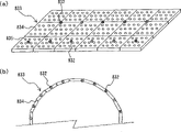
Figure 20 is the ideograph that the example under the situation of spherical screen body is adopted in expression.
Figure 21 is the ideograph that the example under the situation of crt display unit is adopted in expression.
Figure 22 is the ideograph that the example under the situation of LCD is adopted in expression.
Figure 23 is the ideograph that the example under the situation of plasma display is adopted in expression.
Figure 24 is the ideograph that the example under the situation of electroluminescent display is adopted in expression.
Figure 25 (a) and (b) are ideographs of representing to adopt the example under the situation of plane body and spherical surface body light emitting diode indicator respectively.
Figure 26 is the ideograph that expression is arranged in infrared light sources the example under the situation of top board screen section top.
Figure 27 is that expression is arranged in infrared light sources another the routine ideograph under the situation of top board screen section top.
Figure 28 is the ideograph of an example of expression indicating bar.
Figure 29 is the ideograph of an example of presentation video display surface.
Figure 30 is the ideograph of another execution mode of expression location-authentication.
Figure 31 is the ideograph of an example of expression stereoscopic screen body.
Embodiment
[the 1st execution mode]
Figure 11 and Figure 12 represent an execution mode of the application's invention.
This Figure 11 and execution mode shown in Figure 12 at first have as above-mentioned image display device 1: be equivalent to the platform shape body 100 of above-mentioned screen apparatus 11 and the projection arrangement 102 that is equivalent to above-mentioned image projection apparatus 12.
More specifically be, platform shape body 100 has to be the plane and to be the top board screen section 101 of light transmission, projection arrangement 102 is arranged in the below of top board screen section 101, from the rear side projects images opposite with the picture display face of this top board screen section 101.Figure 11 represents to utilize a projection arrangement 102, image projection on the one side of top board screen section 101; Figure 12 represents to arrange 2 projection arrangements 102, and top board screen section 101 is divided into 2 pictures, carries out image projection respectively.Projection arrangement 102 among Figure 12 has: projection main body 103; And optical system 104 such as mirror, be used to make the image of projection from then on to reflect upward, it is directed to top board screen section 101 back sides.
Secondly, as tut output device 2, below top board screen section 101, have infrared light sources array 200, it is made of a plurality of infrared light sources 201 that are equivalent to above-mentioned electromagnetic wave irradiation device 22, also have sound control part 202, it has the function that is equivalent to above-mentioned modulating device 21.
More particularly, each infrared light sources 201 of infrared light sources array 200, corresponding with a plurality of positions in the shown image on the top board screen section 101 respectively, be arranged to array-like, a kind of infrared ray of each position irradiation from the back side of top board screen section 101 to image, this infrared ray is modulated according to acoustic information by sound control part 202.In Figure 12, on top board screen section 101, divide two images that show and aim at, set 6 * 16 some position, arrange infrared light sources 201 with these positions corresponding 6 * 16.And, the projection area is available, with obstruction free projection arrangement 102 (projection main body 103 and optical system 104) to top board screen section 101 projects images.
From the infrared light that this infrared light sources 201 penetrates, modulate according to the acoustic information that is output by sound control part 202.More particularly, change the driving voltage of infrared light sources 201, come that like this intensity that penetrates infrared light is modulated control and get final product according to the voltage level of voice signal.
As described above, on top board screen section 101, demonstrate from the projects images of projection arrangement 102, and, irradiation is under the state of the sound modulated infrared light of infrared light sources array 200 on a plurality of somes positions in this image, utilize the above-mentioned converting means 31 and the tut regenerating unit 32 (referring to Fig. 1) of tut reproduction terminal 3, can receive the sound modulated infrared light and carry out light-to-current inversion, the signal of telecommunication regeneration sound that obtains.
In the present embodiment, finger mounted terminal part 301 with the solar cell 302 that is equivalent to this converting means 31 is installed on terminal use 600 the finger, is installed in terminal use's the ear with these solar cell 302 earplugs 300 that be connected, that be equivalent to audio player 32 by cable (do not have diagram) etc.Like this, if terminal use 600 makes the finger of oneself near on the position of point arbitrarily in the image, more particularly, if make solar cell 302 points of proximity positions that are installed on the finger, then solar cell 302 shines on this position, so accept the tut modulated infrared light, carry out light-to-current inversion, the signal of telecommunication that obtains by light-to-current inversion sends in the earplug 300, output sound intactly, and terminal use 600 can hear this sound.This sound is identical with original acoustic information certainly.
If adopt the acoustic information support system of above present embodiment, then a plurality of terminal uses 600 not only can see the image of being shown on the top board screen section 101 of platform shape body 100, and everyone can both hear terminal use 600 in hope and this image-related acoustic information of liking.That is to say, realized being suitable for respectively each terminal use's 600 acoustic information support.
[the 2nd execution mode]
In this acoustic information support system, also can constitute such system, the acoustic information that promptly further propelling can adapt to each user is respectively supported (also can be described as customizations), carries out the acoustic information support according to the ID and the position of terminal use or terminal itself.
At first, Figure 13 represents to carry out the execution mode that acoustic information is supported according to ID.
In the execution mode of this Figure 13, adopted above-mentioned solar cell 302 and the RFID mark 303 suitable to be arranged to the finger mounted terminal part 301 (referring to the amplification concept map among the figure) of an integral body with above-mentioned ID dispensing device 33 (referring to Fig. 2,7).On the other hand, on platform shape body 100, the read write line 401 that do not hindered 4 corner arrangement that image shows on the top board screen section 101 on this top board.And the output of each read write line 401 is connected with ID authentication department 400.In the present embodiment, read write line 401 and ID authentication department 400 are equivalent to above-mentioned ID checkout gear 4 (referring to Fig. 2,7).In finger mounted terminal part 301, solar cell 302 in order to accept on top board screen section 101 by the sound modulated infrared light of above-mentioned infrared light sources array 200 from the back side illuminaton of top board screen section 101, wishes the sensitive surface of battery is arranged to towards the below.And RFID mark 303 can carry out the ID authentication communication with read write line 401 and get final product.So, both can be arranged on a side opposite with solar cell 302, also can be arranged on an identical side (referring to the amplification concept map among the figure).Under the situation that opposition side is arranged, terminal use 600 refers at read write line 401 up knobs that installing terminal portion 301 turns over and gets final product.
Like this, terminal use 600 under the state that finger installing terminal portion 301 is installed on the finger if make this RFID mark 303 near read write line 401, then carry out data necessary communication between RFID mark 303 and read write line 401, the ID data that read by read write line 401 are sent in the ID authentication department 400.And, according to the ID data of having carried out authentication by ID authentication department 400, can judge automatically is which terminal use 600 is watching image now, moreover, also can send the acoustic information that is suitable for terminal use 600 by sound control part 202 according to this judgement.
At this moment, for example, if set up: the acoustic information database is used to the corresponding acoustic information of ID data of storing and stipulating; And acoustic information choice device, be used for from acoustic information database retrieval select 400 that authenticate by ID authentication department, with the corresponding acoustic information of ID data, so, can realize being only applicable to having indivedual supports of acoustic information of the terminal use 600 of these ID data.
[the 3rd execution mode]
Figure 14 represents about carry out another execution mode that acoustic information is supported according to ID.
In the present embodiment, finger mounted terminal part 301 replaces above-mentioned RFID mark 303, becomes the state (referring to the amplification concept map among the figure) that is arranged to an integral body for light ID mark 304 and solar cell 302.This light ID mark 304 has as above-mentioned shown in Figure 9: infrared light sources 35a such as infrared light LED directional beacon are used to send the ID infrared light; ID storage device 35b is used to store the ID data; And modulating device 35c such as modulation circuit, be used for modulating the ID infrared light according to the ID data.On the other hand, above platform shape body 100, in position go up and arrange a plurality of infrared detectors 402, so that receive ID infrared light from light ID mark 304, output ID data, and, each infrared detector 402 output be connected in the ID authentication department 400.
Like this, under the state that terminal use 600 is installed to finger installing terminal portions 301 on the finger, if send the ID infrared light, this infrared light basis has been stored oneself ID data of this light ID mark 304 and has been modulated, then infrared detector 42 these light of reception carry out demodulation, take out the ID bit string.Then, the same with the execution mode of above-mentioned Figure 13, the 400 pairs of ID data of ID authentication department that receive this ID bit string authenticate, and send the acoustic information that only terminal use 600 with these ID data is suitable for by sound control part 202.
[the 4th execution mode]
Then,, Figure 15 represents to carry out the execution mode that acoustic information is supported about opsition dependent.
In the present embodiment, finger mounted terminal part 301 has become the state (referring to the amplification concept map among the figure) that the circular form reflection sheet 305 that is equivalent to above-mentioned reflection unit 36 (referring to Figure 10) and solar cell 302 are arranged to an integral body.
On the other hand, above platform shape body 100, arranged the device that makes infrared LEDs 502 and infrared camera 501 form an integral body in position.Infrared LEDs 502 is equivalent to be used for the above-mentioned infrared light sources 51 (referring to Figure 10) of occurrence positions with infrared light; Infrared camera 501 is equivalent to above-mentioned infrared pick-up device 52 (referring to Figure 10), and this infrared pick-up device 52 is used to take the position infrared light image that the reflection sheet 305 by above-mentioned finger mounted terminal part 301 reflects.Circular form reflection sheet 305 reflects the light that is subjected on the direction identical with incident direction, so in order to take the infrared light image that reflects exactly, infrared camera 501 and infrared LEDs 502 are arranged near state, constitute an integral body.And, the output of infrared camera 501 is connected to the location-authentication portion 500 that is equivalent to above-mentioned position detecting device 53 (referring to Figure 10), this checkout gear is used for detecting the position of sound reproduction terminal 3 according to the position infrared light image by infrared camera 501 shootings.Location-authentication portion 500 both can be assembled in the one-piece type framework of infrared camera 501 and infrared LEDs 502, also can be arranged to outside independent body.
Like this, the position injects on whole of the cardinal principle of top board screen section 101 from infrared LEDs 502 at ordinary times with infrared light, if finger mounted terminal part 301 enters in this ejaculation district, that is to say, if terminal use 600 takes the finger mounted terminal part 301 on the finger that is installed in oneself on the top board screen section 101, then this circular form reflection sheet 305 is accepted the position infrared light, with inject direction roughly the same direction on reflect.This reflects infrared light circulates in infrared camera 501.Infrared camera 501 is cut off optical filtering by visible light and is made a video recording as bright spot with infrared light with the position, receives that the location-authentication portion 500 of this view data detects the camera relative position of bright spot from frame coordinate by image processing.This detection position is as the position of the finger mounted terminal part 301 on the top board screen section 101 and certified, can judge automatically on which position that finger mounted terminal part 301 is arranged in image now.And, position coordinates on the top board screen section 101 of infrared light sources array 200 irradiation sound modulated infrared light stores in the sound control part 202 in advance, from this irradiation position, select corresponding to the position coordinates of above-mentioned finger mounted terminal part 300, if the sound modulated infrared light is shone on the selecteed irradiation position, terminal use 600 can send to this finger mounted terminal part 301 to acoustic information so, promptly on the position in the indicated image of the finger of oneself.
And, about circular form reflection sheet 305, for example be arranged to a plurality of circular form right-angle prisms laminar, can constitute, position infrared light in order to accept to send from the top as mentioned above by infrared LEDs 502, wish to be arranged in a side opposite with solar cell 302, promptly it is subjected to light reflection surface towards the top, and this solar cell 302 is to accept the sound modulated infrared light sent from the below by infrared light sources array 200.
[the 5th execution mode]
This acoustic information support system also can also realize better independent acoustic information support to above-mentioned the combination according to the acoustic information support of ID with according to the acoustic information support of position.
Figure 16 represents the execution mode of above-mentioned Figure 13 and Figure 15 is combined, and carries out a kind of execution mode that acoustic information is supported according to ID and position.And Figure 17 is in order to further specify the concept map that present embodiment is used, and it is applicable to carries out reference in following explanation.
In the present embodiment, at first, usually from infrared LEDs 502, penetrate the position infrared light, it is circulation reflection in infrared camera 501 by means of the reflection sheet 305 of the finger mounted terminal part 301 on the top board screen section 101, photographic images carries out location-authentication according to camera data in position authentication department 500.That is to say,, can follow the tracks of finger mounted terminal part 301 (referring to Figure 17) as long as made a video recording with infrared light in the position of circulation reflection.
On the other hand, if the RFID mark 303 that terminal use 600 makes finger mounted terminal part 301, then carries out the ID authentication as mentioned above near the some read write lines 401 on the top board.At this moment it is consistent with the position coordinates of read write line 401 to have carried out detecting the position coordinates of finger mounted terminal part 301 of authentication by infrared camera 501 and location-authentication portion 500, if so store the position coordinate of each read write line 401 in advance, so, can automatically judge is to have carried out the ID authentication by which read write line 401; Can make the finger mounted terminal part 301 and the ID data of tracking keep corresponding relation (referring to Figure 17).
And, retrieval is selected and the corresponding acoustic information of above-mentioned authentic ID data, carried out the infrared light of modulation according to it, shine with the corresponding to image of the coordinate position of above-mentioned authentic finger mounted terminal part 301 in the position on, like this, can be on the position in the terminal use's 600 real interested images with these ID data, send the acoustic information that only this terminal use 600 is fit to, and, in the tracking of finger mounted terminal part 301, can carry out this independent acoustic information always exactly and support (referring to Figure 17).
With Figure 17 is that example is described as follows.Having judged a certain individual by the ID authentication is the Japanese, another person is under the foreigner's the situation, follow the tracks of from the position of the read write line 401 that carried out the ID authentication communication respectively (make the ID authentication and follow the tracks of (shooting begins) and carry out getting final product synchronously), to the Japanese, make this finger mounted terminal part 301 during moving on the top board screen section 101, usual on which some position in image, all provide the Japanese acoustic information no matter be; To the foreigner, similarly provide the foreign language acoustic information.
[the 6th execution mode]
Figure 18 represents the execution mode of above-mentioned Figure 14 and Figure 15 is combined, and carries out a kind of execution mode that acoustic information is supported according to ID and position.
In the present embodiment, at first, finger mounted terminal part 301 penetrates the ID infrared light intermittently according to pre-set time interval from light ID mark 304.This ID arrives two different detectors with infrared light through different paths, i.e. infrared detector 402 and infrared camera 501.In infrared detector 402, as mentioned above ID is carried out demodulation with infrared light, take out the ID bit string, in ID authentication department 400, carry out the ID authentication.In infrared camera 501, cut off optical filtering by visible light, catch ID and use infrared light as bright spot, in position authentication department 500, carry out location-authentication.At this moment, infrared light is luminous to carry out in the above-mentioned interval of having fixed time repeatedly, so variation is promptly known its output regularly according to bright spot.That is to say that the camera image that the output of the outer thread detector 402 of the enough lines of energy and infrared camera 501 are taken is synchronous.
On the other hand, as mentioned above, from infrared LEDs 502, penetrate the position infrared light at ordinary times, reflection sheet 305 by the finger mounted terminal part 301 on the top board screen section 101 reflexes in the infrared camera 501 its circulation, carries out location-authentication according to this camera data in position authentication department 500.Because this position infrared light, promptly the bright spot of reflection sheet 305 is different from the bright spot of above-mentioned ID with infrared light, be difficult to eliminate, so, the position that can always follow the tracks of reflection sheet 305, the i.e. position of finger mounted terminal part 301.Therefore, if the bright spot of light ID mark 304 near the bright spot of reflector plate 305, occurs, so, can make by the ID of above-mentioned infrared detector 402 and 400 authentications of ID authentication department corresponding to by the position of above-mentioned infrared camera 501 and 500 authentications of location-authentication portion.That is to say, Yi Bian can often follow the tracks of finger mounted terminal part 301, Yi Bian make detected intermittently id information and positional information keep corresponding relation.
And, retrieval is selected and the corresponding acoustic information of above-mentioned authentic ID data, carried out the infrared light of modulation according to it, shine with the corresponding to image of the coordinate position of above-mentioned authentic finger mounted terminal part 301 in the position on, like this, can be on the position in the terminal use's 600 real interested images with these ID data, send the acoustic information that only this terminal use 600 is fit to, and, in the tracking of finger mounted terminal part 301, can carry out this independent acoustic information always exactly and support (referring to Figure 17).
[the 7th execution mode]
But,, except that adopting above-mentioned RFID mark 303 and light ID mark 304, also can consider to adopt the touch dish about location-authentication.
Figure 19 represents to carry out the execution mode that acoustic information is supported according to the location-authentication that adopts this touch dish.
In the present embodiment, on the top board screen section 101 of platform shape body 100, be provided with touch dish 503.Touch dish 503 is transparent, and image shown on the top board screen section 101 also can be seen by terminal use 600 by touch dish 503.Like this, if terminal use 600 touches touch dish 503, then this position is detected as the position of finger mounted terminal part 301.
Then, by the consistent of irradiation position coordinate of this touch position coordinates harmony tone system infrared light judged, can be the same with above-mentioned situation, the irradiation position of unanimity is carried out independent acoustic information support.Certainly, self-evident, also can be combined with above-mentioned ID authentication.
[other execution modes]
The application's invention is not limited in above execution mode, and the mode of various variations can also be arranged.
[1] for example, in the execution mode of above-mentioned Figure 11~Figure 19, the screen apparatus 11 of image display device 1, employing has the platform shape body 100 of the top board screen section 101 of flat shape, but also can adopt the screen section of curve form, in the case, for example to screen bodies such as sphere and hemisphere faces, can consider from the mode of its back side projects images.
Figure 20 represents an example of the spherical screen body 700 and the projection arrangement 701 of light transmission.Inside at the 360 spherical screen bodies 700 of spending is provided with a plurality of projection arrangements 701, and the sphere district after 701 pairs of quilts of each projection arrangement are divided respectively carries out image projection.In the case, above-mentioned infrared light sources 201 is arranged on the appropriate location by suitable number and gets final product, so that the sound modulated infrared light is shone on the suitable some position in the image.
[2] and, the execution mode of above-mentioned Figure 11~Figure 19 relates to the image display device 1 (referring to Fig. 5) that is made of screen apparatus 11 and image projection apparatus 12.Image display device 1 can adopt crt display unit (=CRT monitor), electroluminescent display (=ELD), light emitting diode indicator (=light-emitting diode display), fluorescent display tube display (VFD), electroluminescent display flat-panel monitors such as (FED) (=various devices such as FPD).Under the situation that adopts arbitrary display unit, also all be to the appropriate location of picture display face, to get final product the sound electromagnetic wave irradiation that is representative with the tut modulated infrared light.
Figure 21 represents an example of crt display unit 801 and infrared light sources 800.In the case, infrared light sources 800 is arranged in suitable number on the appropriate location in picture tube 803 outsides and gets final product, and shines so that can make the sound modulated infrared light see through the face 802 of crt display unit 801 on the suitable some position in the image.Because at this moment on picture tube 803, carry out external coated and inner coating usually, so, needn't prune desire by the coating of the part of infrared light, perhaps adopt the infrared transmission material, make the state that infrared light can fully see through two kinds of retes.Certainly be not limited in the example of this Figure 21.
Figure 22 represents an example of transmission type lcd device 805 and infrared light sources 804.Among Figure 22 806 is back lights; The 807th, polarid filter, the 808th, glass substrate, the 809th, transparency electrode, the 810th, liquid crystal layer, the 811st, filter, the 812nd, glass substrate, the 813rd, polarid filter, the 814th, display surface.In the case, infrared light sources 804 can make the sound modulated infrared light see through each layer and shine on the suitable some position on the display surface 814, gets final product for the light source arrangement of this suitable number in position goes up.On the suitable position of each layer, also can adopt the infrared transmission material.Certainly, be not limited in the example of this Figure 22.
Figure 23 represents an example of plasma display 816 and infrared light sources 815.Among Figure 23 817 is the glass substrates at the back side, the 818th, address electrode (also can be described as data electrode), the 819th, fluorophor, the 820th, the next door, the 821st, show electrode (scan electrode and keep electrode to), the 822nd, dielectric layer, the 823rd, the glass substrate of front.In the case, infrared light sources 815 can make the sound modulated infrared light see through each layer and shine on the suitable some position of carrying out on the glass substrate 823 that image shows, and for this reason, its suitable number is arranged to go up in position and got final product.Also can adopt the material of infrared transmission on the suitable position of each layer.Certainly, be not limited in the example of this Figure 23.
Figure 24 represents an example of transparent electroluminescent display 825 and infrared light sources 824.Among Figure 24 826 is glass substrates, the 827th, and transparency electrode, the 828th, insulating barrier, the 829th, luminescent layer, the 830th, insulating barrier, the 831st, glass substrate.In the case, infrared light sources 824 shines on the suitable some position on the glass substrate 831 in order to make the sound modulated infrared light see through each layer, and its suitable number is arranged on the appropriate location and gets final product.Also can on the suitable position of each layer, adopt the material of infrared transmission.Certainly, be not limited in the example of this Figure 24.
Figure 25 (a) and (b) are represented respectively to arrange a plurality of light-emitting diode panels 834 and plane body and the light emitting diode indicator 833 of spheroid and an example of infrared light sources 832 of formation.Light-emitting diodes plate 834 is to have the plate body that a plurality of compact LEDs (835) form array-like, and its a plurality of connections are set together, and constitutes the light emitting diode indicator 833 of plane body or spheroid.In the case, infrared light sources 832 is to assemble together with other compact LEDs in each light-emitting diode panel 834 itself, perhaps it is assembled in the gap between the light-emitting diode panel 834, the sound modulated infrared light can be shone on the appropriate location get final product.Certainly, be not limited in the example of this Figure 25.
Other flat-panel monitors are not illustrated, still,, the suitable infrared light sources of number is arranged on the appropriate location gets final product similarly for the sound modulated infrared light can be shone on the suitable some position of picture display face.
And in above-mentioned illustrated embodiment, it is many that independent one by one infrared light sources 800,804,815,824 has been arranged, but also can emitting led with face be that the face illuminating source of representative is arranged on the appropriate location.
[3] and, in the above-described embodiment, each infrared light sources is arranged according to the quantity identical with each position in the irradiated image, but, make its each position in image if can change each ultrared direction of illumination of control, so, also can make the irradiation position number in the image different with the light source number, the light source number that lacks than positional number, even only a light source number also can adapt to.
[4] and, in the above-described embodiment, shine the sound modulated infrared light, but also can shine from the picture display face side from the face side that the back side of picture display face is promptly opposite with picture display face.Figure 26 and Figure 27 represent the example under this situation respectively, infrared light sources 201 are arranged in the top of top board screen section 101.And Figure 26 adopts the light source number identical with irradiation position.Figure 27 as mentioned above, infrared light sources 201 full reclinings drive, and can change the control direction of illumination, the light source number is less than the irradiation position number.
[4] infrared light sources 201, for example can adopt infrarede emitting diode (=infrared LED).
[5] according to the distance of the picture display face that arrives various image display devices, increase more under the situation of light quantity, also can itself make the structure that forms by a plurality of infrared LED set to each infrared light sources 201.
[6] the electromagnetic wave irradiation device 22 of voice output 2 except that adopting above-mentioned infrared light sources 201, also can adopt the various light sources that can export other light such as luminous ray.
[7] and, light source not only adopts LED, also can adopt laser, also it is also conceivable that to make these light shine the locational mode of each point in the image by optical cables such as optical fiber.
[8] certain, also can consider to adopt light various electromagnetic waves such as electric wave in addition.In the case, adopt the electromagnetic wave source that adapts with it.And, self-evident, about above-mentioned various execution modes, also must make its formation can adapt to each electromagnetic wave.
[9] and, in the execution mode of above-mentioned Figure 11~Figure 19, finger mounted terminal part 301 with solar cell 302, RFID mark 303, light ID mark 304, reflection sheet 305 can be installed on terminal use 600 the finger, but can not be mounted on the finger yet, but can be installed in health installing terminal portion on the part of healths such as hand or pin.As long as can make the some position in its contact or the approaching image that shows.So, like this, not only can be installed on the part of health, and for example also can consider shown in the image pattern 28, can be installed on the indicating bar 900 that terminal use 600 has or be assembled in the indicating bar in advance.
In Figure 28, on mounting bar on the front end of retractile indicating bar 900 installing terminal portion 901 and make its loading and unloading freely.Installing terminal portion 901 is by entering the lead 902 (also can pass through its outside) in the indicating bar 900 on this rod, be connected on earplug and the sound reproduction terminal parts 903 such as headband earphone, loud speaker, from the next output signal of telecommunication regeneration sound of solar cell (not having diagram).And for example, can be installed on terminal use 600 the ear as the earplug and the earphone unit of sound reproduction terminal part 903, loud speaker can be carried by terminal use 600.
[10] and, the sound guidance system that this acoustic information support system also can be used as the visual disability human uses.Which in the case, do not know so for example the illustration among Figure 29 is such, can on each irradiation position of picture display face, little hole 1000 be set on the position of electromagnetic wave irradiations such as infrared light in the image yet.So, visual disability people promptly knows irradiation position by touching hole 1000, can accept acoustic information exactly and support.
And,, can judge when ID authenticates that so also can judge according to this provides the acoustic information that is fit to the visual disability people to expression if be that visual disability people's bit string is embedded in the ID data.
At this moment, for example, make up with location-authentication, also can lead, illustrate, next irradiation position or hole 1000 just can be found to which direction moveable finger or indicating bar etc. in irradiation position from the image of present touch or above-mentioned hole 1000.For example, the sound indication is proposed, " being slightly to the right next hole thus ", " thus slightly forwards, just have broadcast about ... the hole of explanation sound " etc.Certainly, this guiding also can be applicable to healthy normal people.
[11] and, in the execution mode of above-mentioned Figure 15, Figure 16, Figure 18, carry out the top that infrared camera 501 that location-authentication uses and infrared LEDs 502 are arranged on top board screen section 101, but also can for example shown in Figure 30ly be arranged on the below.In the case, wish that reflection sheet 305 is arranged on a side identical with solar cell 301, receive the position infrared light that comes from the below, it is circulated repeatedly.(with reference to the enlarged drawing among the figure).
[12] and, in the execution mode of above-mentioned Figure 11~Figure 20, (platform shape body 100 and spherical screen body 700 with top board screen section 101 have no any concavo-convex neat plane or curved picture display face to be equivalent to the part of the screen apparatus 11 of image display device 1.But also can adopt screen apparatus 11 combined, that have concavo-convex picture display face such as making plane and curved surface.Figure 31 represents an example in the case.Carry out image projection for stereoscopic screen body 1100 from projection arrangement 1101, show relief map etc.,, shine the sound modulated infrared light from infrared light sources 1102 to the appropriate location in this relief map with concavo-convex picture display face.
[13] and, about image display device 1, be not limited only to by the such various screen apparatus 11 of above-mentioned execution mode and image projection apparatus 12 and the device that constitutes, so long as the device of display image gets final product, so, for example, at screen body originally coating on one's body or printing image, can see through with above-mentioned infrared light is the acoustic information support system that the electromagnetic device etc. of representative also can be applicable to the application's invention.
As above detailed description, if adopt the application's invention, brand-new acoustic information support system then can be provided, promptly on screen on the optional position in the shown image, as long as the user indicates or touches this position, the acoustic information relevant can be heard at an easy rate, the acoustic information support that everyone adapts with the user who watches image respectively can be realized with display image.
Claims (31)
1, a kind of acoustic information support system is characterized in that comprising:
Image display device is used for display image;
Voice output is used for to the one or more positions by the shown image of image display device, and the electromagnetic wave of modulation has been carried out in output according to acoustic information;
The sound reproduction terminal, comprising: utilize the position in the above-mentioned image to receive above-mentioned electromagnetic wave and it is transformed into the converting means of the signal of telecommunication and the audio player that the signal of telecommunication of being obtained by this converting means is carried out sound reproduction.
2, a kind of acoustic information support system is characterized in that having:
Image display device is used for display image;
Voice output is used for to the one or more positions by the shown image of image display device, and the electromagnetic wave of modulation has been carried out in output according to acoustic information;
Audio player, comprising: utilize the position in the above-mentioned image to receive above-mentioned electromagnetic wave and it is transformed into the converting means of the signal of telecommunication and the ID dispensing device that the signal of telecommunication of being obtained by this converting means is carried out the audio player of sound reproduction and sends ID; And
The ID checkout gear is used to detect the ID that the ID dispensing device by the sound reproduction terminal sends.
3, a kind of acoustic information support system is characterized in that having:
Image display device is used for display image;
Voice output is used for to the one or more positions by the shown image of image display device, and the electromagnetic wave of modulation has been carried out in output according to acoustic information;
The sound reproduction terminal, comprising: utilize the position in the above-mentioned image to receive above-mentioned electromagnetic wave and it is transformed into the converting means of the signal of telecommunication and the audio player that the signal of telecommunication of being obtained by this converting means is carried out sound reproduction; And
Position detecting device is used to detect the position of sound reproduction terminal.
4, a kind of acoustic information support system is characterized in that having:
Image display device is used for display image;
Voice output is used for to the one or more positions by the shown image of image display device, and the electromagnetic wave of modulation has been carried out in output according to acoustic information;
The sound reproduction terminal, comprising: utilize the position in the above-mentioned image to receive above-mentioned electromagnetic wave and it is transformed into the converting means of the signal of telecommunication and the ID dispensing device that the signal of telecommunication of being obtained by this converting means is carried out the audio player of sound reproduction and sends ID;
The ID checkout gear is used to detect the ID that the ID dispensing device by the sound reproduction terminal sends; And
Position detecting device is used to detect the position of sound reproduction terminal.
5, as each the described acoustic information support system in the claim 1~4, it is characterized in that: above-mentioned image display device has: the screen apparatus of display image and the image projection apparatus of image projection to this screen apparatus;
6, acoustic information support system as claimed in claim 5 is characterized in that: screen apparatus, its picture display face are plane, curved surface shapes or concavo-convex planar.
7, acoustic information support system as claimed in claim 5 is characterized in that: screen apparatus, its picture display face is a light transmission.
8, acoustic information support system as claimed in claim 5 is characterized in that: image projection apparatus, projects images from the above-mentioned screen apparatus of its picture display face side direction.
9, acoustic information support system as claimed in claim 5 is characterized in that: image projection apparatus projects images from the above-mentioned screen apparatus of opposing face side direction of this picture display face.
10, as each the described acoustic information support system in the claim 1~4, it is characterized in that: image display device is a crt display unit.
11, as each the described acoustic information support system in the claim 1~4, it is characterized in that: image display device is a flat-panel monitor.
12, acoustic information support system as claimed in claim 11 is characterized in that: flat-panel monitor is a certain in LCD, plasma display, electroluminescent display, light emitting diode indicator, fluorescent display tube display and the electroluminescent display.
13, as each the described acoustic information support system in the claim 1~4, it is characterized in that: voice output has: come the modulating device of modulated electromagnetic wave and the locational electromagnetic wave irradiation device of the electromagnetic wave irradiation after being modulated by modulating device in the above-mentioned image according to acoustic information.
14, acoustic information support system as claimed in claim 13 is characterized in that: the electromagnetic wave irradiation device has the electromagnetic electromagnetic wave source of output.
15, acoustic information support system as claimed in claim 14, it is characterized in that: electromagnetic wave source is a plurality of, it is corresponding with a plurality of positions in the above-mentioned image respectively and arrange.
16, acoustic information support system as claimed in claim 14, it is characterized in that: electromagnetic wave source is one or more, it can be changed to direction of illumination on a plurality of positions in the above-mentioned image.
17, acoustic information support system as claimed in claim 14 is characterized in that: electromagnetic wave source is the light source of output as electromagnetic light.
18, acoustic information support system as claimed in claim 17 is characterized in that: light source is light-emitting diode or laser.
19, acoustic information support system as claimed in claim 17 is characterized in that: the light that comes is shone on the position in the above-mentioned image by optical cable.
20, acoustic information support system as claimed in claim 17, it is characterized in that: the converting means of sound reproduction terminal is a kind of photo-electric conversion device, is used for receiving the light that comes from the above-mentioned light source of above-mentioned electromagnetic wave irradiation device and carries out light-to-current inversion.
21, acoustic information support system as claimed in claim 20, it is characterized in that: photo-electric conversion device is a solar cell.
22, as each the described acoustic information support system in the claim 1~4, it is characterized in that: the converting means of audio player can be installed on the part of terminal use's health.
23, acoustic information support system as claimed in claim 22 is characterized in that: the part of health is hand or pin.
24, as each the described acoustic information support system in the claim 1~4, it is characterized in that: the converting means of audio player can be installed on the indicating bar that the terminal use has or be assembled in its inside.
25, as each the described acoustic information support system in the claim 1~4, it is characterized in that: the tut regenerating unit of sound reproduction terminal is earplug or earphone unit or loud speaker.
26, as each the described acoustic information support system in the claim 1~4, it is characterized in that: the sound reproduction terminal is the non-transformer terminal that does not need other driving power.
27, as each the described acoustic information support system in the claim 1~4, it is characterized in that: the ID dispensing device of sound reproduction terminal is the RFID mark, above-mentioned ID checkout gear be and this RFID mark between carry out the read-write heads of ID authentication communication.
28, as each the described acoustic information support system in the claim 1~4, it is characterized in that: the ID dispensing device of sound reproduction terminal is a light ID mark, above-mentioned ID checkout gear is a kind of infrared detector, be used to receive the ID infrared light that sends by this light ID mark, output ID numerical value.
29, acoustic information support system as claimed in claim 28, it is characterized in that: light ID mark 35 has: ID comes modulating device that ID is modulated with infrared light with the ID storage device of the infrared light sources of infrared light, storage ID data and according to the ID data, infrared detector is accepted after this light ID mark modulation and the ID infrared light that sends is exported the ID data.
30, as each the described acoustic information support system in the claim 1~4, it is characterized in that: position detecting device has: the position is used to take the position infrared light of being returned by the sound reproduction end reflection with infrared light sources, the infrared pick-up device of infrared light; And position detecting device, be used for detecting the position of sound reproduction terminal according to position infrared light picture by the shooting of infrared pick-up device; The tut reproduction terminal has a kind of reflection unit, is used to reflect the position infrared light that is sent by position detecting device.
31, as each the described acoustic information support system in the claim 1~4, it is characterized in that: position detecting device has: the touch dish, and it is arranged on the picture display face of above-mentioned image display device; And position detecting device, the position that is used for this touch dish of touching according to the terminal use detects the position of sound reproduction terminal.
Applications Claiming Priority (2)
| Application Number | Priority Date | Filing Date | Title |
|---|---|---|---|
| JP2002364471A JP4228069B2 (en) | 2002-12-16 | 2002-12-16 | Voice information support system |
| JP364471/2002 | 2002-12-16 |
Publications (1)
| Publication Number | Publication Date |
|---|---|
| CN1754404A true CN1754404A (en) | 2006-03-29 |
Family
ID=32588239
Family Applications (1)
| Application Number | Title | Priority Date | Filing Date |
|---|---|---|---|
| CNA200380106385XA Pending CN1754404A (en) | 2002-12-16 | 2003-12-16 | Audio information support system |
Country Status (7)
| Country | Link |
|---|---|
| US (1) | US8073155B2 (en) |
| EP (1) | EP1583392A4 (en) |
| JP (1) | JP4228069B2 (en) |
| KR (1) | KR20060028757A (en) |
| CN (1) | CN1754404A (en) |
| AU (1) | AU2003289362A1 (en) |
| WO (1) | WO2004056153A1 (en) |
Cited By (1)
| Publication number | Priority date | Publication date | Assignee | Title |
|---|---|---|---|---|
| CN106856583A (en) * | 2015-12-08 | 2017-06-16 | 安讯士有限公司 | Methods, devices and systems for controlling the acoustic image in audio region |
Families Citing this family (8)
| Publication number | Priority date | Publication date | Assignee | Title |
|---|---|---|---|---|
| JP2007005926A (en) * | 2005-06-21 | 2007-01-11 | National Institute Of Information & Communication Technology | Audio information providing system and audio information providing method |
| JP2007005927A (en) * | 2005-06-21 | 2007-01-11 | National Institute Of Information & Communication Technology | Audio information providing system and audio information providing method |
| US9524047B2 (en) * | 2009-01-27 | 2016-12-20 | Disney Enterprises, Inc. | Multi-touch detection system using a touch pane and light receiver |
| JP5448611B2 (en) | 2009-07-02 | 2014-03-19 | キヤノン株式会社 | Display control apparatus and control method |
| KR20110080894A (en) * | 2010-01-07 | 2011-07-13 | 삼성전자주식회사 | Method and apparatus for processing multi-touch input |
| KR102052372B1 (en) * | 2013-01-11 | 2019-12-05 | 엘지전자 주식회사 | Apparatus and Method for transmitting and receiving data using earphone |
| US10322057B2 (en) * | 2013-02-22 | 2019-06-18 | Ashley Diana Black International Holdings, Llc | Fascia tissue fitness device |
| KR102448771B1 (en) | 2021-11-29 | 2022-09-29 | (주) 케이앤지앰테크 | Wind power generation system for modeling |
Family Cites Families (13)
| Publication number | Priority date | Publication date | Assignee | Title |
|---|---|---|---|---|
| US3245157A (en) * | 1963-10-04 | 1966-04-12 | Westinghouse Electric Corp | Audio visual teaching system |
| US3273260A (en) * | 1964-10-06 | 1966-09-20 | Tutortape Lab Inc | Audio-visual communication systems and methods |
| US4336018A (en) * | 1979-12-19 | 1982-06-22 | The United States Of America As Represented By The Secretary Of The Navy | Electro-optic infantry weapons trainer |
| IL81146A (en) * | 1986-01-26 | 1990-04-29 | Avish Jacob Weiner | Sound-producing amusement or educational devices |
| JP3298196B2 (en) * | 1992-12-25 | 2002-07-02 | カシオ計算機株式会社 | Input device and electronic musical instrument provided with the input device |
| JPH08263006A (en) * | 1995-03-23 | 1996-10-11 | Unitec Kk | Voice guiding device |
| JPH09214430A (en) * | 1996-01-31 | 1997-08-15 | Sony Corp | Infrared ray transmitter |
| JPH10222108A (en) * | 1997-02-10 | 1998-08-21 | Syst Sekkei:Kk | Radio wave sensing alarm device |
| US6445369B1 (en) * | 1998-02-20 | 2002-09-03 | The University Of Hong Kong | Light emitting diode dot matrix display system with audio output |
| GB2361345B (en) * | 1999-03-16 | 2002-03-27 | Innomind Internat Ltd | Display, and device having a display |
| EP1906294B1 (en) * | 1999-05-03 | 2018-07-18 | Symbol Technologies, LLC | Wearable communication system |
| US7099568B2 (en) | 2000-03-21 | 2006-08-29 | Sony Corporation | Information playback apparatus and electronic pop advertising apparatus |
| JP2002116858A (en) | 2000-10-06 | 2002-04-19 | Sony Corp | Electronic pop advertisement device |
-
2002
- 2002-12-16 JP JP2002364471A patent/JP4228069B2/en not_active Expired - Lifetime
-
2003
- 2003-12-16 AU AU2003289362A patent/AU2003289362A1/en not_active Abandoned
- 2003-12-16 EP EP03780790A patent/EP1583392A4/en not_active Withdrawn
- 2003-12-16 US US10/539,350 patent/US8073155B2/en not_active Expired - Fee Related
- 2003-12-16 KR KR1020057011156A patent/KR20060028757A/en not_active Application Discontinuation
- 2003-12-16 CN CNA200380106385XA patent/CN1754404A/en active Pending
- 2003-12-16 WO PCT/JP2003/016110 patent/WO2004056153A1/en active Application Filing
Cited By (1)
| Publication number | Priority date | Publication date | Assignee | Title |
|---|---|---|---|---|
| CN106856583A (en) * | 2015-12-08 | 2017-06-16 | 安讯士有限公司 | Methods, devices and systems for controlling the acoustic image in audio region |
Also Published As
| Publication number | Publication date |
|---|---|
| US8073155B2 (en) | 2011-12-06 |
| KR20060028757A (en) | 2006-04-03 |
| JP4228069B2 (en) | 2009-02-25 |
| AU2003289362A8 (en) | 2004-07-09 |
| WO2004056153A1 (en) | 2004-07-01 |
| US20080025548A1 (en) | 2008-01-31 |
| JP2004200815A (en) | 2004-07-15 |
| EP1583392A4 (en) | 2008-12-03 |
| AU2003289362A1 (en) | 2004-07-09 |
| EP1583392A1 (en) | 2005-10-05 |
Similar Documents
| Publication | Publication Date | Title |
|---|---|---|
| USRE49084E1 (en) | Display panel and mobile terminal | |
| CA2620149C (en) | Input method for surface of interactive display | |
| CN2590031Y (en) | Light conducting device, photoelectric device and electronic equipment | |
| TWI258111B (en) | Display panel device | |
| US20070160222A1 (en) | Positioning audio output for users surrounding an interactive display surface | |
| CN1196305C (en) | Illuminator and portable information apparatus with the same illuminator | |
| CN100340954C (en) | Multimedia presentation computing device | |
| CN1918428A (en) | Surface light source device | |
| CN1643897A (en) | Mobile telephone device having camera and illumination device for camera | |
| CN1599895A (en) | On a substrate formed or resting display arrangement | |
| CN1646974A (en) | Backlight assembly for liquid crystal display apparatus | |
| CN1599444A (en) | Projector | |
| CN1754404A (en) | Audio information support system | |
| KR101685989B1 (en) | Mobile terminal | |
| JP2016532248A (en) | Lighting for audio equipment | |
| KR20150133048A (en) | Mobile terminal | |
| CN1197633C (en) | Entertainment apparatus and monitor device used therein | |
| US10613345B2 (en) | Mixed reality assembly and method of generating mixed reality | |
| CN1623622A (en) | Method and apparatus for dice eye number determination and electronic device using the determinater | |
| CN1664774A (en) | Input device | |
| CN1658193A (en) | Communication apparatus and system handling viewer image | |
| KR20160038409A (en) | Mobile terminal and method for controlling the same | |
| CN1187682C (en) | Image displaying device and program read by computer | |
| JP2000137218A (en) | Lcd back light structure | |
| CN114631309A (en) | Information processing apparatus, information processing method, and program |
Legal Events
| Date | Code | Title | Description |
|---|---|---|---|
| C06 | Publication | ||
| PB01 | Publication | ||
| C10 | Entry into substantive examination | ||
| SE01 | Entry into force of request for substantive examination | ||
| C02 | Deemed withdrawal of patent application after publication (patent law 2001) | ||
| WD01 | Invention patent application deemed withdrawn after publication |