CN1715018A - Sheet cutter - Google Patents
Sheet cutter Download PDFInfo
- Publication number
- CN1715018A CN1715018A CNA2005100531228A CN200510053122A CN1715018A CN 1715018 A CN1715018 A CN 1715018A CN A2005100531228 A CNA2005100531228 A CN A2005100531228A CN 200510053122 A CN200510053122 A CN 200510053122A CN 1715018 A CN1715018 A CN 1715018A
- Authority
- CN
- China
- Prior art keywords
- recess
- guide rail
- foot
- substrate
- cutting knife
- Prior art date
- Legal status (The legal status is an assumption and is not a legal conclusion. Google has not performed a legal analysis and makes no representation as to the accuracy of the status listed.)
- Pending
Links
Images


Classifications
-
- B—PERFORMING OPERATIONS; TRANSPORTING
- B26—HAND CUTTING TOOLS; CUTTING; SEVERING
- B26D—CUTTING; DETAILS COMMON TO MACHINES FOR PERFORATING, PUNCHING, CUTTING-OUT, STAMPING-OUT OR SEVERING
- B26D1/00—Cutting through work characterised by the nature or movement of the cutting member or particular materials not otherwise provided for; Apparatus or machines therefor; Cutting members therefor
- B26D1/01—Cutting through work characterised by the nature or movement of the cutting member or particular materials not otherwise provided for; Apparatus or machines therefor; Cutting members therefor involving a cutting member which does not travel with the work
- B26D1/12—Cutting through work characterised by the nature or movement of the cutting member or particular materials not otherwise provided for; Apparatus or machines therefor; Cutting members therefor involving a cutting member which does not travel with the work having a cutting member moving about an axis
- B26D1/14—Cutting through work characterised by the nature or movement of the cutting member or particular materials not otherwise provided for; Apparatus or machines therefor; Cutting members therefor involving a cutting member which does not travel with the work having a cutting member moving about an axis with a circular cutting member, e.g. disc cutter
- B26D1/20—Cutting through work characterised by the nature or movement of the cutting member or particular materials not otherwise provided for; Apparatus or machines therefor; Cutting members therefor involving a cutting member which does not travel with the work having a cutting member moving about an axis with a circular cutting member, e.g. disc cutter coacting with a fixed member
- B26D1/205—Cutting through work characterised by the nature or movement of the cutting member or particular materials not otherwise provided for; Apparatus or machines therefor; Cutting members therefor involving a cutting member which does not travel with the work having a cutting member moving about an axis with a circular cutting member, e.g. disc cutter coacting with a fixed member for thin material, e.g. for sheets, strips or the like
-
- B—PERFORMING OPERATIONS; TRANSPORTING
- B26—HAND CUTTING TOOLS; CUTTING; SEVERING
- B26D—CUTTING; DETAILS COMMON TO MACHINES FOR PERFORATING, PUNCHING, CUTTING-OUT, STAMPING-OUT OR SEVERING
- B26D7/00—Details of apparatus for cutting, cutting-out, stamping-out, punching, perforating, or severing by means other than cutting
- B26D7/0006—Means for guiding the cutter
-
- B—PERFORMING OPERATIONS; TRANSPORTING
- B26—HAND CUTTING TOOLS; CUTTING; SEVERING
- B26D—CUTTING; DETAILS COMMON TO MACHINES FOR PERFORATING, PUNCHING, CUTTING-OUT, STAMPING-OUT OR SEVERING
- B26D7/00—Details of apparatus for cutting, cutting-out, stamping-out, punching, perforating, or severing by means other than cutting
- B26D7/20—Cutting beds
-
- B—PERFORMING OPERATIONS; TRANSPORTING
- B26—HAND CUTTING TOOLS; CUTTING; SEVERING
- B26D—CUTTING; DETAILS COMMON TO MACHINES FOR PERFORATING, PUNCHING, CUTTING-OUT, STAMPING-OUT OR SEVERING
- B26D1/00—Cutting through work characterised by the nature or movement of the cutting member or particular materials not otherwise provided for; Apparatus or machines therefor; Cutting members therefor
- B26D1/01—Cutting through work characterised by the nature or movement of the cutting member or particular materials not otherwise provided for; Apparatus or machines therefor; Cutting members therefor involving a cutting member which does not travel with the work
- B26D1/04—Cutting through work characterised by the nature or movement of the cutting member or particular materials not otherwise provided for; Apparatus or machines therefor; Cutting members therefor involving a cutting member which does not travel with the work having a linearly-movable cutting member
- B26D1/045—Cutting through work characterised by the nature or movement of the cutting member or particular materials not otherwise provided for; Apparatus or machines therefor; Cutting members therefor involving a cutting member which does not travel with the work having a linearly-movable cutting member for thin material, e.g. for sheets, strips or the like
-
- B—PERFORMING OPERATIONS; TRANSPORTING
- B26—HAND CUTTING TOOLS; CUTTING; SEVERING
- B26D—CUTTING; DETAILS COMMON TO MACHINES FOR PERFORATING, PUNCHING, CUTTING-OUT, STAMPING-OUT OR SEVERING
- B26D1/00—Cutting through work characterised by the nature or movement of the cutting member or particular materials not otherwise provided for; Apparatus or machines therefor; Cutting members therefor
- B26D1/01—Cutting through work characterised by the nature or movement of the cutting member or particular materials not otherwise provided for; Apparatus or machines therefor; Cutting members therefor involving a cutting member which does not travel with the work
- B26D1/12—Cutting through work characterised by the nature or movement of the cutting member or particular materials not otherwise provided for; Apparatus or machines therefor; Cutting members therefor involving a cutting member which does not travel with the work having a cutting member moving about an axis
- B26D1/14—Cutting through work characterised by the nature or movement of the cutting member or particular materials not otherwise provided for; Apparatus or machines therefor; Cutting members therefor involving a cutting member which does not travel with the work having a cutting member moving about an axis with a circular cutting member, e.g. disc cutter
- B26D1/157—Cutting through work characterised by the nature or movement of the cutting member or particular materials not otherwise provided for; Apparatus or machines therefor; Cutting members therefor involving a cutting member which does not travel with the work having a cutting member moving about an axis with a circular cutting member, e.g. disc cutter rotating about a movable axis
- B26D1/18—Cutting through work characterised by the nature or movement of the cutting member or particular materials not otherwise provided for; Apparatus or machines therefor; Cutting members therefor involving a cutting member which does not travel with the work having a cutting member moving about an axis with a circular cutting member, e.g. disc cutter rotating about a movable axis mounted on a movable carriage
- B26D1/185—Cutting through work characterised by the nature or movement of the cutting member or particular materials not otherwise provided for; Apparatus or machines therefor; Cutting members therefor involving a cutting member which does not travel with the work having a cutting member moving about an axis with a circular cutting member, e.g. disc cutter rotating about a movable axis mounted on a movable carriage for thin material, e.g. for sheets, strips or the like
-
- B—PERFORMING OPERATIONS; TRANSPORTING
- B26—HAND CUTTING TOOLS; CUTTING; SEVERING
- B26D—CUTTING; DETAILS COMMON TO MACHINES FOR PERFORATING, PUNCHING, CUTTING-OUT, STAMPING-OUT OR SEVERING
- B26D7/00—Details of apparatus for cutting, cutting-out, stamping-out, punching, perforating, or severing by means other than cutting
- B26D2007/0012—Details, accessories or auxiliary or special operations not otherwise provided for
- B26D2007/0087—Details, accessories or auxiliary or special operations not otherwise provided for for use on a desktop
-
- Y—GENERAL TAGGING OF NEW TECHNOLOGICAL DEVELOPMENTS; GENERAL TAGGING OF CROSS-SECTIONAL TECHNOLOGIES SPANNING OVER SEVERAL SECTIONS OF THE IPC; TECHNICAL SUBJECTS COVERED BY FORMER USPC CROSS-REFERENCE ART COLLECTIONS [XRACs] AND DIGESTS
- Y10—TECHNICAL SUBJECTS COVERED BY FORMER USPC
- Y10T—TECHNICAL SUBJECTS COVERED BY FORMER US CLASSIFICATION
- Y10T83/00—Cutting
- Y10T83/748—With work immobilizer
- Y10T83/7487—Means to clamp work
- Y10T83/7493—Combined with, peculiarly related to, other element
- Y10T83/7507—Guide for traveling cutter
-
- Y—GENERAL TAGGING OF NEW TECHNOLOGICAL DEVELOPMENTS; GENERAL TAGGING OF CROSS-SECTIONAL TECHNOLOGIES SPANNING OVER SEVERAL SECTIONS OF THE IPC; TECHNICAL SUBJECTS COVERED BY FORMER USPC CROSS-REFERENCE ART COLLECTIONS [XRACs] AND DIGESTS
- Y10—TECHNICAL SUBJECTS COVERED BY FORMER USPC
- Y10T—TECHNICAL SUBJECTS COVERED BY FORMER US CLASSIFICATION
- Y10T83/00—Cutting
- Y10T83/869—Means to drive or to guide tool
- Y10T83/8821—With simple rectilinear reciprocating motion only
- Y10T83/8822—Edge-to-edge of sheet or web [e.g., traveling cutter]
Landscapes
- Life Sciences & Earth Sciences (AREA)
- Forests & Forestry (AREA)
- Engineering & Computer Science (AREA)
- Mechanical Engineering (AREA)
- Details Of Cutting Devices (AREA)
- Nonmetal Cutting Devices (AREA)
Abstract
Sheet cutter minimizing friction occurred between a slider and a guide rail while transferring the slider along the guide rail in a high linearity. Each of the slider and the guide rail has either a convex or a concave portion up and down to fit each other. In cutting processes only the convex and concave portions are made abutted each other contributing to minimization of the friction and smooth transferability of the slider in a high linearity.
Description
Technical field
The present invention relates to be used for mainly is the cutter of the sheet material of paper, more specifically, relates to the sheet cutter that keeps chi to cut sheet by its location, dependence paper.
Background of invention
Japanese Unexamined Patent Publication No 11-33978 (hereinafter referred to as D1) has disclosed a sheet material cutter, wherein movingly slider is mounted to the guide rail in T type cross section, and be placed in the substrate in such mode, just make the guide recess and the guiding surface that on the leader of this slider, form be assemblied in this guide rail.Japanese Unexamined Patent Publication No 6-262586 (hereinafter referred to as D2) relates to the cutter that is used for paper again, it has disclosed the assembling groove that will be used for sheet cutter and has formed parallel with the guide rail that is provided with in the substrate, and shearing and sheet material pressing means movably be arranged on the place, end of assembling groove, is beneficial to change easily the cutter sheet material.Japanese Unexamined Patent Publication No 11-309695 (hereinafter referred to as D3) relates to the locking mechanism in paper maintenance chi, and disclosed and keep chi movably to be arranged on the guide rail (concave or camber) on paper, this guide rail is formed on the erecting bed with cutter guide rail quadrature.With lever will be for example the locking piece of pressing plate add and be pressed on the guide rail, this bar bar is provided with paper and keeps chi, thereby keeps chi to be locked in the appropriate location that the user selects on paper.At last, Japanese Unexamined Patent Publication No 5-337879 (hereinafter referred to as D4) relates to the sheet cutter that is used for paper, and disclosed with the paper keeper be that one and the guiding foot quadrature setting movably are assemblied in groove, this sheet holding member and the guide rail quadrature on the sheet holding member.Locking piece is added on the inwall that is pressed in this groove by handling a lever, this lever is provided with the paper localization part, thereby the paper localization part is locked in the selectable location.
In D1, the guide rail that makes the guide recess that on the leader of slider, forms and guiding surface be assemblied in T type cross section, thus slider and guide rail adjacency closely on whole surface is directed slider in higher linearity.Because is higher in its contact surface rate between slider and the guide rail in aforesaid D1, the too early wearing and tearing during therefore may being created in.In D2, cutter sheet material pressing means is removably disposed in the end of assembling groove, thereby it helps the easier transposing of cutter paper.But need the cutter sheet material be fit into about how the further improvement of the operating aspect in the assembling groove.In D3, paper keeps chi movably to be arranged on the guide rail that forms on the erecting bed, and makes paper keep chi to be locked by lever.But in this structure, it can not be applied to lock this chi when paper keeps chi to be in outside the erecting bed.In D4, with the paper localization part be one and movably be assemblied in the groove that on sheet holding member, forms with the guiding foot of its quadrature setting.Owing to make the paper localization part by the lever locking that is provided with, identical with D3, so it can not be applied to this chi and is in occasion outside the sheet holding member.
Summary of the invention
Designed the present invention with the viewpoint that overcomes above-mentioned shortcoming, one first purpose of the present invention provides sheet cutter, it has the slider that is installed on guide rail, and makes frictional resistance minimum between slider and guide rail, and can be at guided slidable device on the guide rail, in higher linearity.One second purpose of the present invention provides sheet cutter, and wherein the cutting knife pad can easily be installed at suprabasil assembling groove or from its demolition.One the 3rd purpose of the present invention provides sheet cutter, and wherein paper keeps chi to be locked in the substrate, also is like this even it is positioned at outside the substrate.Below some aspect of the present invention of these above-mentioned purposes is finished in narration.
In a first aspect, sheet cutter comprises: substrate; Be arranged on suprabasil guide rail; And be provided with cutting knife and movably be installed in slider on the guide rail, wherein slider and guide rail have part convexity or concave at above-below direction separately, so that assembling mutually.So be configured, in cutting process, only make this convexity to abut against mutually, to cause the friction minimum that between slider and guide rail, produces with part concave.Slider can also along guide rail, in higher linearity easy motion.
In first second aspect, two contact positions additionally are set from a side to opposite side between slider and guide rail, and this two contact position is separated from each other according to first aspect.Because being in contact with one another of slider and guide rail do not occur over just convexity and part concave the place that above-below direction is provided with, and occur in two contact positions that add that are provided with from a side to opposite side, so also can keep together with guide rail even sheet cutter is in the obliquity slider.But, in cutting process, only make this convexity to be in contact with one another, thereby slider and guide rail have less friction each other with part concave.
In a third aspect, sheet cutter comprises: substrate; Be arranged on suprabasil guide rail; Be provided with cutting knife and movably be installed in slider on the guide rail; And be positioned at cutting knife pad on the top surface of substrate and that be installed in the assembling groove that forms along guide rail.Near assembling groove, be provided with leader, so that towards assembling groove guiding cutting knife pad.So structure when transposing cutting knife pad, only requires the user that the cutting knife pad is placed on leader.In case be placed on leader, by it self weight the guiding of cutting knife pad entered assembling groove, thereby simplified its transposing operation.
In first fourth aspect, at least one end of assembling groove the pivoting end keeper is set, so that the cutting knife pad is remained in the assembling groove according to the third aspect.Even be in heeling condition, still the cutting knife pad is remained in the assembling groove by the pivoting end keeper at sheet cutter.
According to the third aspect one the 5th aspect, at an end of assembling groove the end securing member is set also, an end of fixed cutting tool pad, the other end at assembling groove is provided with the pivoting end keeper simultaneously, keeps the other end of cutting knife pad.The cutting knife pad can remain in the assembling groove reliably, and the transposing operation of having simplified the cutting knife pad once more.
Aspect one the 6th, sheet cutter comprises: substrate; Be arranged on suprabasil guide rail; Be provided with cutting knife and movably be installed in slider on the guide rail; And be arranged on paper on the top surface of substrate and that be installed in the guide recess that is provided with the guide rail quadrature and keep chi.Paper keeps chi to have the foot that is provided with its quadrature, thereby makes it can be removable along guide recess.Between foot's (and guide recess), positioner is set also, can makes paper keep chi to be placed in certain position.So be configured,, can make foot be fixed in guide recess reliably by positioner even paper keeps chi to be placed in outside the top surface of substrate.
According to one the 7th aspect aspect the 6th, positioner comprises: the recess that forms in foot or substrate; Can be with this recess engagement or from its projection that moves; And the protruding operating parts that keeps projection engages.So be configured, be easy to make projection to remove with the recess engagement or from it by operating this projection operating parts simply.
According to the eight aspect aspect the 6th and the 7th, the middle concave cross section of guide recess is formed: the bottom closure width that makes it is than its open-top wider width, thereby foot is remained in the guide recess.No matter whether use sheet cutter, paper keeps chi to keep together with guide recess reliably.
According to one the 9th aspect aspect the 6th, positioner comprises: be arranged on the recess on the top surface of foot or substrate; And with leaf spring projection integrally formed and that be pushed towards recess.Because leaf spring has projection,, thereby simplified its structure so positioner only needs to have less part.
According to 1 the tenth aspect aspect the 6th, positioner comprises: be arranged on the recess on the top surface of foot or substrate, and on the top surface of foot or substrate projection integrally formed and that be pushed towards recess.Because both are formed on recess and projection in foot or the substrate, so it has successfully reduced the desired number of spare parts of positioner.Therefore can form positioner by simply foot being fit into substrate.
According to 1 the tenth aspect the 6th on the one hand, positioner comprises: be arranged on the recess in the foot; And be arranged on suprabasil and with operating parts by linkage towards the movable projection of recess.The positioner of the force-applying piece of leaf spring compares with for example having, and substrate can further stably be fixed in foot.
According to 1 the 12 aspect aspect the 6th, positioner comprises: be formed on the recess on the top surface of substrate; And the projection that is pushed towards recess by force application structure.Because positioner is fit into foot, has further simplified its structure.
According to the either side of above-mentioned aspects 1 the 13 aspect, sheet cutter can have handle, so that improve portable.
The accompanying drawing summary
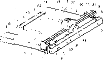
Fig. 1 is the stereogram according to sheet cutter of the present invention, and wherein paper keeps chi to be fixed on certain position, and the cutting knife pad will be fit in the assembling groove;
Fig. 2 is the plan view from above according to sheet cutter of the present invention, and wherein paper keeps chi to be fixed on outside the erecting bed of substrate;
Fig. 3 is the rearview according to sheet cutter of the present invention;
Fig. 4 is that wherein paper keeps chi to be fixed on the erecting bed along the cutaway view of the line X-X intercepting of Fig. 2;
Fig. 5 A is the enlarged drawing of circle district D among Fig. 4, and Fig. 5 B is the schematic diagram that is illustrated in the slipper between slider and the guide rail;
Fig. 6 is the schematic diagram that is illustrated in another embodiment of the slipper between slider and the guide rail;
Fig. 7 A is the enlarged drawing of circle district A among Fig. 1, and Fig. 7 B is the enlarged diagram that cutting knife pad, assembling groove and leader are shown;
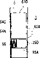
Fig. 8 is the enlarged drawing of circle district B among Fig. 2;
Fig. 9 A, 9B and 9C be respectively the enlarged drawing of circle district C among Fig. 3, in one first embodiment keeper exploded view and have the side view of the prodger of projection;
Figure 10 A and 10B are illustrated in topology view engagement and out of mesh state, the keeper in one second embodiment respectively, and Figure 10 C is the profile among Figure 10 A;
Figure 11 A and 11B are illustrated in structure chart engagement and out of mesh state, the keeper in one the 3rd embodiment;
Figure 12 A and 12B are illustrated in structure chart engagement and out of mesh state, the keeper in one the 4th embodiment;
Figure 13 A and 13B are illustrated in structure chart engagement and out of mesh state, the keeper in one the 5th embodiment;
Figure 14 A and 14B are illustrated in structure chart engagement and out of mesh state, the keeper in one the 6th embodiment;
Figure 15 A, 15B and 15C are the structure charts of keeper in one the 7th embodiment; Figure 15 A has gone out fixing state, and Figure 15 B is the cutaway view along the line Y-Y intercepting of Figure 15 A, and Figure 15 C illustrates the not cutaway view of stationary state;
Figure 16 A and 16B are illustrated in structure chart engagement and out of mesh state, the keeper in one the 8th embodiment; And
Figure 17 A and 17B are illustrated in structure chart engagement and out of mesh state, the keeper in one the 9th embodiment.
The specific embodiment
Hereinafter with reference to accompanying drawing narration embodiments of the invention.Sheet cutter 1 consists essentially of substrate 2, guide rail 30, slider 40, cutting knife pad 50 and paper and keeps chi 60.At first, as illustrated in fig. 1 and 2, substrate 2 roughly is square, and is made by the suitable material of for example synthetic resin, and its top surface has erecting bed 3, places for example sheet material of paper on erecting bed 3.Guide rail 30 is removably disposed in the long side of substrate 2 and along this length side setting, as shown in Figure 1, is provided with assembling groove 4 (see figure 7)s of assembling cutting knife pad 50 simultaneously along guide rail 30.On the erecting bed 3 of substrate 2, form a pair of guide recess 8,8 with guide rail 30 quadratures.In guide recess 8,8, be provided with can slide along guide recess 8,8 keep the integrally formed a pair of foot 61,61 of chi 60 with paper.Arbitrary short side in substrate 2 can also be provided with handle 27.
The present invention is not limited to the above, but can be provided with handle 27 in two short sides of substrate 2, perhaps at least one side of two short sides of substrate 2 indicating section that for example is used for address (ads) is set instead.Perhaps, distributor or analog can be set replace indicating section, be used to store interconvertible cutting knife.
Secondly, the details of guide rail and slider below is described.Shown in Fig. 1 and 5, guide rail 30 has vertically continuous inclined-plane 34 at two upsides, and removably is configured to along the long side of substrate 2 and has for example elastic component of helical spring (not shown).The top surface of guide rail 30 has vertically continuous recessed groove 31, and two bottoms of guide rail 30 have vertically continuous and the mate 33,33 cutting, that comprise top surface 33A, 33A and side surface 33B, 33B from the bottom.This mate can have another structure, for example Ao Ru groove.
When being placed on slider 40 on the guide rail 30, slide protrusion 41 contacts with the groove 31 of middle concave.But, as previously discussed, because the inner surface of slider 40 is similar to the outer surface of guide rail 30, but bigger slightly, between lateral sliding crowning 41A, the 41A of the slide protrusion 41 of groove surface 31A, the 31A of the side direction of the groove 31 of middle concave and camber, form certain interval than it.That is to say,, between side direction recessed groove surface 31A, 31A and lateral sliding crowning 41A, 41A, contact without any the surface except between bottom middle concave groove surface 31B and the basal sliding crowning 41B.This class slider 40 moves in higher linearity.In this embodiment, mesh bulge 43,43 and mate 33,33 are not contacted mutually by having certain interval betwixt.That is to say, respectively at top mesh bulge face 43A, 43A and top mate surface 33A, 33A and also between side mesh bulge face 43B, 43B and side mate surface 33B, 33B, have the gap.
When along guide rail 30 these sliders 40 of slip, the local contact may take place with side recessed groove surface 31A, 31A in side slip crowning 41A, 41A, even but in this case, mesh bulge 43,43 still keeps not contacting mutually with mate 33,33.Since along the groove 31 of concave for this reason with higher linearity guided slidable projection 41, so can make the abrasion minimum that between slider and guide rail, takes place.The length of recessed groove surface 31A, 31A by making side slip crowning 41A, 41A and slip is longer, can improve linearity again.
Keeping with handle 27 or carrying under the situation that sheet cutter is a heeling condition, top mesh bulge face 43A, 43A or side mesh bulge face 43B, 43B or both abut against top mate surface 33A, 33A or side mate surface 33B, 33B or both respectively.Thereby can prevent that slider 40 from skidding off from guide rail 30.
Shown in Figure 4 and 5, guide rail 30 also has pressing means 35, adds laminated sheet along it in cutting process, and between pressing means 35 and erecting bed 3 certain clearance is set also, is used for placing therein sheet material.Under idle state, make guide rail 30 upwards, be used to form this gap.The aspect down, at first makes the slider 40 of the cutting knife 45 (for example rotating blade) that is provided with in cutting knife keeper 44 be displaced sideways in working order in addition, arrives an end of guide rail 30, is used for sheet material is put into this gap.The slider 40 that pressurizes downwards then, guide rail 30 correspondingly pressurizes.When adding laminated sheet by pressing means 35, the slider 40 that has cutting knife 45 slides along guide rail, so that sheet material is cut into selectable size.
In another embodiment, as shown in Figure 6, the top surface of guide rail 30A can have the projection 32 of camber, and simultaneously slider 40A is at slipper 42 that can the tool middle concave corresponding to the position of the projection 32 that camber is set.Thereby the projection of camber 32 is assembled to the slipper 42 of middle concave.When the projection 32 of camber was assemblied in the slipper 42 of middle concave, the slipper of the convex surfaces 32B of top camber and bottom middle concave surface 42B contacted; But the convex surfaces 32A of side direction camber, 32A do not contact in the face of keeping mutually with side direction middle concave slipper surface 42A, 42A.Between the slipper surface of convex surfaces 32A, the 32A of side direction camber and side direction middle concave 42A, 42A, form certain interval, so that slider 40A can slide with higher linearity on guide rail 30A.And the mesh bulge 43,43 that forms in two bottoms of slider 40A, in inside is formed into the mate 33,33 that two bottoms at guide rail 30A form because certain interval and not contacting.This means between top mesh bulge surface 43A, 43A and top mate surface 33A, 33A, and also between lateral engagement convex surfaces 43B, 43B and lateral engagement part surface 33B, 33B, certain clearance is set respectively.
Next illustrates the cutting knife pad.As illustrated in fig. 1 and 2,, be provided with end securing member 6 integratedly, so that an end 51 of fastening cutting knife pad 50 with substrate 2 at an end of assembling groove 4.At the other end of assembling groove 4, for substrate 2 pivoting end keeper 7 is set pivotly, so that keep the other end 52 of cutting knife pad 50.Wherein, cutting knife pad 50 can be an any structure, as long as can be assembled to assembling groove 4.
As end securing member 6, pivoting end keeper 7 has and falls L shaped section substantially.Shown in Fig. 7 A (in hold mode not), a distolateral assembling groove 4 can open wide, so that cutting knife pad 50 can be installed in wherein.By leader 5 after assembling groove 4 guiding cutting knife pads 50, will be in not that the pivoting end keeper 7 of holding position (Fig. 7 A) upwards rotates this moment, make its inner surface abut against the other end 52 of cutting knife pad 50.Rotate this rotation end and keep 7 until arriving stop position, the other end 52 of further pressurizeing in this position.By above operation, cutting knife pad 50 is firmly fixed at assembling groove 4.
In the time of in cutting knife pad 50 is maintained at assembling groove 4, by end securing member 6 and pivoting end keeper 7 both ends 51,52 from top and both sides restriction cutting knife pad 50.Regardless of being with the maintenance of handle tilt ground or carrying sheet cutter that cutting knife pad 50 can both keep together with fitting recess 4 securely.When assembling groove 4 removes cutting knife pad 50, the holding position of pivoting end keeper 7 from it rotated, so that leave an end of assembling groove 4.Because the other end 52 of cutting knife pad 50 is not by topped, the user can dismantle cutting knife pad 50 simply with hand.
Secondly, leader will be described.Shown in Fig. 1,2,4 and 7, a pair of guide portion 5,5 that cutting knife pad 50 is guided to assembling groove 4 is set, and with substrate 2 be one. Leader 5,5 is placed near the two ends of assembling groove 4, and still the spacing between is formed into shorter than the length of cutting knife pad 50. Leader 5,5 comprises sloping portion 5A, the 5A that is formed into to tilt towards assembling groove 4.Its angle of inclination can be selected, but consider when being placed on cutting knife pad 50 on sloping portion 5A, the 5A, can slip into assembling groove 4 by its own wt cutting knife pad, thereby can determine this angle of inclination.
The structure of leader is not limited to said structure.But three or more leader can be arranged, perhaps sloping portion can be optional value, as long as can reposefully the guiding of cutting knife pad be entered assembling groove by hand or any other instrument.
Followingly explain that with reference to Fig. 1 and 2 paper keeps chi and guide recess.At two short side places of substrate 2 with guide rail 30 a pair of positioning step 11,11 of locating sheet material is set orthogonally.On the erecting bed 3 of substrate 2, also have a pair of guide recess 8,8 with guide rail 30 quadratures, in this groove, guide paper to keep the foot 61,61 of chi 60 slidably.This two guide recess 8,8 has the cross section and is roughly trapezoidal concave shape, and foot 61,61 has the section shape of the projection that is assembled and remains on guide recess 8,8 places, the section shape of guide recess 8,8 can be any inverted T-shaped, as long as it has the bottom than the closure of open-top broad.
Corresponding to the section of guide recess 8,8, form the section that paper keeps the foot 61,61 of chi 60 with inverted T-shaped.Even tilt to place sheet cutter 1, fine foot 61,61 of being fixed in guide recess 8,8 can not be drawn out from this guide recess yet.Though narration later on, by with in projection 25,25 recesses that are introduced in the foot 61,61, foot 61,61 more stably is fixed in guide recess 8,8.
Have integratedly and with the paper of a pair of foot 61,61 of its quadrature setting keep chi 60 have a side of location sheet material, simultaneously at the maintenance bar 63,63 of two tip side.When paper being kept chi 60 be placed on the erecting bed 3, bar 63,63 can work with the mate (not shown), so that mesh with guide recess 8,8.Thereby paper is kept chi 60 location and is fixed on a certain position.
The positioner of first embodiment is described with reference to Fig. 2,3 and 8 secondly.The erecting bed 3 of substrate 2 has the recess 9 with guide recess 8,8 quadratures.The projection 25,25 integrally formed with excrescence 24,24 (will be described in detail later on) is assemblied in recess 9 slidably.Keep chi 60 to be placed and to be fixed under the situation of outside of erecting bed 3 at paper, projection 25,25 meshes with the recess 62,62 of foot 61,61.The rear surface of substrate 2 has a pair of bottom recesses 10,10 in the position corresponding to guide recess 8.Be fixed in the bottom recesses 10,10 by the foot 61,61 that paper is kept chi 60, paper can be kept chi 60 location and be fixed on certain position.
As shown in Figure 9, positioner 12 comprises: a pair of protruding part 24,24, and they are set in a pair of protruding leader 13,13 that forms with respect to a pair of bottom recesses 10,10 quadratures; Promote the spring 23,23 of protruding part 24,24 towards bottom recesses 10,10; The protruding operating parts 17 that keeps recess 62,62 engagements of projection 25,25 and foot 61,61; And be placed at a pair of intermediary operation spare 21,21 between protruding operating parts 17 and the spring 23,23.
Consult Fig. 9, paired protruding leader 13,13 and intermediary operation leader 14,14 are arranged on the dorsal part of substrate 2 integratedly and also are between the paired bottom recesses 10,10.Junction between protruding leader 13,13 and bottom recesses 10,10 is formed with the top surface that runs through protruding leader 13,13 and recess 9,9 (see figure 8)s of erecting bed 3.Between bottom recesses 10,10, on the back side of substrate 2, be provided with the retaining part 15 that movably keeps protruding operating parts 17 integratedly.Retaining part 15 is provided with a step, and protruding operating parts 17 can be between retaining part 15 and the erecting bed 3.Referring to Fig. 4.
Shown in Fig. 3 and 9, protruding operating parts 17 has a pair of pressures partially 19,19, this pressures partially with respect to protruding operating parts 17 travel directions tilt about 45 the degree.Retaining part 15 has the screwed hole of mounting screw 20.The surface of projection operating parts 17 has operating surface 18 (seeing Fig. 2 and 4), and protruding operating parts 17 is fit into retaining part 15, makes operating surface 18 be in erecting bed 3 substantially on the same horizontal plane.By mounting screw 20, can movably keep protruding operating parts 17 along the guiding slotted hole 16 that on retaining part 15, forms.Protruding part 24,24 the one end be provided with integratedly again the projection 25,25 and within it portion have spring retaining part 26,26.Wherein, an end of intermediary operation spare 21,21 is contacted with spring 23,23, and its other end have the pressing surfaces 22,22 with 45 degree inclinations.
Be installed in the substrate 2 with the positioner 12 of following step first embodiment.At first in this way protruding operating parts 17 is fitted into the retaining part 15 on the back side that is arranged on substrate 2, promptly pressures partially 19,19 is towards guide rail 30.Mounting screw 20 is introduced into guiding slotted hole 16, is installed in then in the screw of protruding operating parts 17. Bossy body 24,24 is placed on the inside of protruding leader 13,13, so that make projection 25,25 be fitted into recess 9,9.Then intermediary operation spare 21,21 is introduced intermediary operation leader 14,14.Secondly spring 23,23 is pressurized and be fit between the spring retaining part 26,26 and intermediary operation leader 14,14 of protruding part 24,24.In this state, the pressures partially 19,19 that protrudes operating parts 17 abuts against the pressing surfaces 22,22 of intermediary operation spare 21,21.Towards guide recess 8,8 o'clock, the recess 62,62 that forms in projection 25,25 and the foot 61,61 that keeps chi 60 at paper meshes.After positioner 12 was installed on the back side of substrate 2, positioner 12 can be avoided exposing optionally by topped.
In first embodiment, when needs keep paper to keep chi 60, at first protrude operating parts 17, to give spring 23,23 more energy towards a side shifting of guide rail 30.Make towards the outstanding projection 25,25 of guide recess 8,8 by spring 23,23 and to mesh with the recess 62,62 that is formed in the foot 61,61 that is fixed.The aspect when changing the position of paper maintenance chi 60, moves protrusion operating parts 17, to reduce the energy of spring 23,23 simply with the direction of leaving guide rail 31 in addition.Foot 61,61 becomes and can move along guide recess 8,8.On the basis of said structure, can shorten significantly and be used to time of cutting sheet and being spent.
Secondly, below will narrate the positioner of other embodiment, promptly concentrate on the structure of foot and projection.In second embodiment of positioner, as shown in figure 10, an end of leaf spring 70,70 is fixed to side 10A, the 10A of the bottom recesses 10,10 that on the back side of erecting bed 3, forms with screw 73,73. Leaf spring 70,70 has the sweep 71,71 towards guide recess 8,8 bendings.Sweep 71,71 is outstanding towards guide recess 8,8 by hole 10B, 10B, with foot 61,61 on recess 62,62 engagements.The other end of leaf spring 70,70, leaf spring end 72,72 movably are held with respect to the storage part 74,74 that forms on side 10A, the 10A of bottom recesses 10,10.
For locate in a second embodiment and fixedly paper keep chi 60, the step that need take is: 1) along guide recess 8,8 foot 61,62 is in state outside the recess 62,62 from the sweep shown in Figure 10 B 71,71 and moves to sweep 71,71 shown in Figure 10 A and 10C and be in state in the face of recess 62,62; 2) make sweep 71,71 outstanding by elastic force towards recess; And 3) make sweep 71,71 and recess 62,62 engagements.According to above-described second embodiment, because the sweep of leaf spring has replaced projection, it has constructed positioner than first embodiment with less part.
In the 3rd embodiment of positioner, as shown in figure 11, as shown in figure 11, the end of leaf spring 70A, 70A is fixed on the back side of the 61A of foot, 61A, for example on a side 64A, the 64A of the 61A of foot, 61A with screw 73A.Leaf spring 70A, 70A have towards sweep 71A, the 71A of erecting bed 3 bendings.Sweep 71A, 71A are outstanding towards aperture 64B, 64B, so that be engaged on recess 62A, 62A on the erecting bed 3.The other end of leaf spring 70A, 70A, leaf spring end 72A, 72A movably are held in storage part 74A, the 74A on side 64A, the 64A that is formed on the 61A of foot, 61A.
For location in the 3rd embodiment and fixedly paper keep chi 60, need take the following step: the state that 1) is in along guide recess 8,8 from sweep 71A, the 71A shown in Figure 11 B outside recess 62A, the 62A moves to sweep 71A, 71A shown in Figure 11 A in the face of the state of recess 62A, 62A with the 61A of foot, 61A; 2) make sweep 71A, 71A outstanding with elastic force towards recess 62A, 62A; And 3) sweep 71A, 71A and recess 62A, 62A engagement.According to above-described the 3rd embodiment, can obtain the effect identical with second embodiment.
In the 4th embodiment of positioner, as shown in figure 12,, cutouts 75,75 is set by to the back side of erecting bed 3, especially near the back portion excavation of the erecting bed 3 of bottom recesses 10,10. Cutouts 75,75 is in evagination part 25A, the 25A and the deflection area 76,76 that is integrally formed therewith of the both sides place of convex portion 25A, 25A outside that have in the face of guide recess 8,8 places in the central.Thereby evagination part and recess 62,62 engagements that are formed on formation on the shank 61,61.
For location in the 4th embodiment and fixedly paper keep chi 60, need take the following step: the state that 1) is in along guide recess 8,8 from evagination part 25A, 25A shown in Figure 12 B outside the recess 62,62 moves to evagination part 25A, 25A shown in Figure 12 A in the face of the state of recess 62,62 with foot 61,61; 2) elasticity with deflector 76,76 makes evagination part 25A, 25A outstanding towards recess 62,62; And 3) evagination part 25A, 25A and recess 62,62 engagements.According to above-described the 4th embodiment, can realize further reducing the effect of part than the second and the 3rd embodiment.
In the 5th embodiment of positioner, as shown in figure 13, by providing cutouts 75A, 75A to the 61B of foot, 61B excavation.In the face of the surface of cutouts 75A, the 75A of erecting bed 3 has in the central evagination part 25B, 25B and integrally formed deflection area 76A, the 76A in place, both sides of convex portion 25B, 25B outside.Thereby evagination part 25B, 25B and the recess 62A, the 62A that are formed on the erecting bed 3 mesh.
For location in the 5th embodiment and fixedly paper keep chi 60, need take the following step: the state outside recess 62A, the 62A of 1) being in along guide recess 8,8 from evagination part 25B, 25B shown in Figure 13 B makes the 61B of foot, 61B arrive as shown in FIG. 13A evagination part 25B, 25B in the face of the state of recess 62A, 62A; 2) elastic force with deflection area 76A, 76A makes evagination part 25B, 25B outstanding towards recess 62A, 62A; And 3) make evagination part 25B, 25B and recess 62A, 62A engagement.According to above-described the 5th embodiment, can obtain the effect identical with the 4th embodiment.
In the 6th embodiment of positioner, as shown in figure 14, on the back side of erecting bed 3, roughly one first hole 82 and second hole 83,83 of quadrature are set mutually.Form first hole 82 at equidirectional with foot 61 motion, simultaneously and guide recess 8,8 lateral cross ground form second hole 83,83.At 82 places, first hole, on pivotable connector 80, movably assemble a first connecting rod 77 and a second connecting rod 78.At 83,83 places, two second holes, movably be assemblied in the axial part 81,81 in addition that respectively holding of first connecting rod 77 and second connecting rod 78 is provided with on 79,79.As shown in Figure 14B, each end parts 79,79 outstanding guide recess 8,8 that enter, consequently the recess 62,62 with foot 61,61 meshes.Pivotable connector 80 also has the operating parts (not shown in FIG.), this operating parts operation first connecting rod 77 and second connecting rod 78.
For location in the 6th embodiment and fixedly paper keep chi 60, need take the following step: 1) 79,79 states that are in outside the recess 62,62 of foot 61,61 of respectively holding along guide recess 8,8 from first connecting rod 77 shown in Figure 14 A and second connecting rod 78 move to as shown in Figure 14B each end 79,79 in the face of the state of recess 62,62 with foot 61,61; 2) but move the operating parts of an end that is connected in hinge connector 80 along second hole 82; 3) make respectively hold 79,79 outstanding towards the side of guide recess 8,8; And 4) make the engagement of end 79,79 and recess.According to above-described the 6th embodiment, because unlike above-mentioned other embodiment, elasticity of demand is not set tries hard to recommend the moving for example projection or the part of evagination, thus the foot of paper-retaining device is fixed more firmly, thus produce more stable shearing manipulation.
In the 7th embodiment of positioner, as shown in figure 15, on the back side of erecting bed 3, one first hole 82A is set perpendicular to erecting bed 3, be parallel to erecting bed 3 simultaneously one second hole 83A, 83A are set.Form the second hole 83A, 83A in direction so with foot 61 moving direction lateral cross.The first hole 82A is arranged in the appropriate area on the back side of erecting bed 3.At the first slotted hole 82A place, but on hinge connector 80A, movably assemble a first connecting rod 77A and a second connecting rod 78A.At the second hole 83A, 83A place, respectively hold 79A, the 79A of first connecting rod 77A and second connecting rod 78A are provided with axial part 81A, 81A.Shown in Figure 15 A, the outstanding guide recess 8,8 that enters of each end 79A, 79A, consequently the recess 62,62 with foot 61,61 meshes.Pivotable connector 80A also has operating parts 84, this operating parts operation first connecting rod 77A and second connecting rod 78A.
For the paper of locating and fix among the 7th embodiment keeps chi 60, need take the following step: 1) state that is in outside the recess of foot 61,61 of each end 79A, the 79A along guide recess 8,8 from first connecting rod 77A shown in Figure 15 C and second connecting rod 78A moves to each end 79A, 79A shown in Figure 15 B in the face of the state of recess 62,62 with foot 61,61; 2) with operating parts 84 pivotable connector 80A is moved along the second hole 82A; 3) make each end 79A, 79A outstanding towards the side of guide recess 8,8; And 4) make end 79A, 79A and recess 62,62 engagements.According to above-mentioned the 7th embodiment, can obtain the effect identical with the 6th embodiment.
In the 8th embodiment of positioner, as shown in figure 16, at the back side of the 61C of foot, 61C, for example on side 64A, the 64A, with the end of screw 73B, the fastening leaf spring 70B of 73B, 70B.Its other end has towards the side of erecting bed 3 outstanding protruding 25C, 25C.Integrally formed protruding 25C, 25C is outstanding from guide recess 85,85 on the side of the 61C of foot, 61C 64A, 64A, thus with erecting bed 3 on recess 62A, the 62A engagement that forms.
For the paper of locating and being fixed among the 8th embodiment keeps chi 60, need take the following step: the state that 1) is in along guide recess 8,8 from protruding 25C, the 25C shown in Figure 16 B outside recess 62A, the 62A moves the state of protruding 25C, the 25C of the 61C of foot, 61C arrival shown in Figure 16 A in the face of recess 62A, 62A; 2) elastic force with leaf spring 70B, 70B makes protruding 25C, 25C outstanding towards recess 62A, 62A; And 3) make protruding 25C, 25C and recess 62A, 62A engagement.According to above-described the 8th embodiment, equally with other embodiment can shorten the required time of shearing manipulation.
In the 9th embodiment of positioner, as shown in figure 17, leader 85A, 85A integrally formed on the back side of the 61D of foot, 61D extend to another side 64C, 64C from side 64A, 64A in the face of erecting bed 3. Leader 85A, 85A keep helical spring 86,86 and protruding 25D, 25D therein, so that by helical spring 86,86 protruding 25D, 25D are promoted towards the side of erecting bed 3.Thereby make protruding 25D, 25D outstanding, so that mesh with the recess 62A, the 62A that are formed on the erecting bed 3 from leader 85A, 85A.
For the paper of locating and being fixed among the 9th embodiment keeps chi 60, need take the following step: 1) state that is in from protruding 25D, 25D shown in Figure 17 B outside recess 62A, the 62A that is formed on the erecting bed 3 along guide recess 8,8 moves to protruding 25D, 25D shown in Figure 17 A in the face of the state of recess 62A, 62A with the 61D of foot, 61D; 2) elastic force with helical spring 86,86 makes protruding 25D, 25D outstanding towards recess 62A, 62A; And 3) make protruding 25D, 25D and recess 62A, 62A engagement.According to above-described the 9th embodiment, can obtain the effect identical with the 8th embodiment.
Though in the 8th and the 9th embodiment, narrated leaf spring 70B, 70B and helical spring 86,86 respectively, be not limited to these force application structures, but can be any material or structure, as long as they have elastic characteristic.
Claims (13)
1. a sheet material cutter, it comprises: substrate; Be arranged on suprabasil guide rail; Be provided with cutting knife and movably be installed in slider on the guide rail, wherein slider and guide rail have the middle convex portion or the dished portion of above-below direction separately, are assembled together mutually to cause slider and guide rail.
2. according to the described sheet cutter of claim 1, it is characterized in that: between slider and guide rail, two contact positions additionally are set in such mode, this two contact position is separated from each other from a side to opposite side.
3. a sheet material cutter, it comprises: substrate; Be arranged on suprabasil guide rail; Be provided with cutting knife and movably be installed in slider on the guide rail; And be placed on the top surface of substrate and be installed in cutting knife pad in the assembling groove that forms along guide rail, leader wherein is set, so that towards assembling groove guiding cutting knife pad near assembling groove.
4. according to the described sheet cutter of claim 3, it is characterized in that: at least one end place at assembling groove is provided with the pivoting end keeper, so that the cutting knife pad is remained in the assembling groove.
5. according to the described sheet cutter of claim 3, it is characterized in that: the end place at assembling groove is provided with the end securing member, an end that is used for fastening cutting knife pad, the other end at assembling groove is provided with the pivoting end keeper simultaneously, is used to keep the other end of cutting knife pad.
6. a sheet material cutter, it comprises: substrate; Be arranged on suprabasil guide rail; Be provided with cutting knife and movably be installed in slider on the guide rail; Guide recess that on the top surface of substrate, form and that be provided with the guide rail quadrature; And the paper that can regulate the location in guide recess keeps chi, wherein paper keeps chi to be provided with foot integratedly and orthogonally, so that slidably, also between foot and guide recess, positioner is set, so that determine that selectively paper keeps the position of chi along guide recess.
7. according to the described sheet cutter of claim 6, it is characterized in that: positioner comprises: be formed on foot or suprabasil recess; Projection with the recess engagement; And the protruding operating parts that keeps projection engages.
8. according to claim 6 or the described sheet cutter of claim 7, it is characterized in that: guide recess has the bottom closure width than open-top wider width, so that keep foot therein.
9. according to the described sheet cutter of claim 6, it is characterized in that: positioner comprises: be arranged on the recess on the top surface of foot or substrate; Leaf spring; And with leaf spring projection integrally formed, that be pushed towards recess.
10. according to the described sheet cutter of claim 6, it is characterized in that: positioner comprises: be arranged on the recess on the top surface of foot or substrate; And on the top surface of foot or substrate projection integrally formed and that be pushed towards recess.
11. according to the described sheet cutter of claim 6, it is characterized in that: positioner comprises: be arranged on the recess in the foot; And be arranged in the substrate and with operating parts by linkage towards the movable projection of recess.
12. according to the described sheet cutter of claim 6, it is characterized in that: positioner comprises: be formed on the recess on the top surface of substrate, and the projection that is pushed towards recess by force application structure.
13. according to claim 1 each described sheet cutter to claim 12, it is characterized in that: sheet cutter can have handle.
Applications Claiming Priority (2)
| Application Number | Priority Date | Filing Date | Title |
|---|---|---|---|
| JP2004189964A JP4565322B2 (en) | 2004-06-28 | 2004-06-28 | Cutting machine |
| JP2004189964 | 2004-06-28 |
Publications (1)
| Publication Number | Publication Date |
|---|---|
| CN1715018A true CN1715018A (en) | 2006-01-04 |
Family
ID=34933661
Family Applications (1)
| Application Number | Title | Priority Date | Filing Date |
|---|---|---|---|
| CNA2005100531228A Pending CN1715018A (en) | 2004-06-28 | 2005-02-28 | Sheet cutter |
Country Status (5)
| Country | Link |
|---|---|
| US (1) | US20050284278A1 (en) |
| EP (1) | EP1612008A1 (en) |
| JP (1) | JP4565322B2 (en) |
| CN (1) | CN1715018A (en) |
| AU (1) | AU2005200613A1 (en) |
Cited By (6)
| Publication number | Priority date | Publication date | Assignee | Title |
|---|---|---|---|---|
| CN102271880A (en) * | 2009-03-16 | 2011-12-07 | 咖路事务器株式会社 | Cutting tool |
| CN103395083A (en) * | 2007-07-03 | 2013-11-20 | 大卫·平特 | Cutting assembly |
| CN103640263A (en) * | 2013-11-19 | 2014-03-19 | 佘峰 | Guide die of bidirectional embossing machine |
| CN105965562A (en) * | 2016-06-29 | 2016-09-28 | 苏州金螳螂建筑装饰股份有限公司 | Adjustable gypsum plate cutter |
| CN107443463A (en) * | 2016-05-30 | 2017-12-08 | 普乐士株式会社 | Cutter |
| CN109060402A (en) * | 2018-10-26 | 2018-12-21 | 陕西科技大学 | A kind of electrodynamic type bar shaped leather sampler |
Families Citing this family (12)
| Publication number | Priority date | Publication date | Assignee | Title |
|---|---|---|---|---|
| US7415915B2 (en) * | 2005-04-05 | 2008-08-26 | Elmer's Products, Inc. | Cutting system having an interchangeable rotary blade cartridge |
| US7811016B2 (en) * | 2005-05-25 | 2010-10-12 | Agfa Graphics Nv | Flatbed printing machine |
| JP4780604B2 (en) * | 2005-10-07 | 2011-09-28 | カール事務器株式会社 | Paper positioning mechanism |
| DE202006002004U1 (en) * | 2006-02-07 | 2007-06-21 | Weidmüller Interface GmbH & Co. KG | stripping tool |
| WO2008124837A2 (en) * | 2007-04-10 | 2008-10-16 | Acco Brands Usa Llc | Sheet trimmer |
| US20120045557A1 (en) * | 2010-08-20 | 2012-02-23 | Traci Chapple | Baked Good Marking Device and Method of Using the Same |
| GB201106279D0 (en) * | 2011-04-14 | 2011-05-25 | Collins Craig | "Creasing accessory and method of providing a crease in a substrate" |
| JP6280734B2 (en) * | 2013-12-13 | 2018-02-14 | プラス株式会社 | Cutting machine |
| US20170036365A1 (en) * | 2015-08-04 | 2017-02-09 | Gary DARWIN | Sheet material cutting guide and ruler |
| CN105538385B (en) * | 2016-01-08 | 2017-06-30 | 宁波市恺丰文具礼品有限公司 | A kind of papery English character and digital maker |
| US11590670B2 (en) * | 2019-05-31 | 2023-02-28 | The Boeing Company | Methods and apparatus to align applique cutters |
| CN112549160B (en) * | 2020-11-25 | 2022-09-13 | 长沙爱邦数控科技有限公司 | Movable cross beam structure of vibration knife cutting machine and installation process flow thereof |
Family Cites Families (22)
| Publication number | Priority date | Publication date | Assignee | Title |
|---|---|---|---|---|
| GB1098031A (en) * | 1964-04-07 | 1968-01-03 | Sidney R Littlejohn & Company | A punch |
| US3792636A (en) * | 1972-12-05 | 1974-02-19 | Milton Bradley Co | Paper trimmer |
| JPS5599296U (en) * | 1978-12-27 | 1980-07-10 | ||
| US4867023A (en) * | 1987-02-11 | 1989-09-19 | The Fletcher-Terry Company | Mat bevel cutting machine |
| JP2984873B2 (en) * | 1992-05-29 | 1999-11-29 | カール事務器株式会社 | Paper cutting machine |
| US5325752A (en) * | 1992-06-10 | 1994-07-05 | Chesapeake Corporation | Cutter instrument for precision cutting of rectangular shapes from a corrugated cardboard sheet |
| JPH06262586A (en) * | 1993-03-16 | 1994-09-20 | Karl Jimuki Kk | Paper cutting machine |
| US5819618A (en) * | 1994-05-10 | 1998-10-13 | Martin Yale Industries, Inc. | Rotary paper trimmer |
| US5537904A (en) * | 1994-08-11 | 1996-07-23 | Albin; Stephen D. | Reversible mat cutter |
| US5802942A (en) * | 1995-10-10 | 1998-09-08 | Fiskars Inc. | Paper trimmer |
| WO1997039863A1 (en) * | 1996-04-25 | 1997-10-30 | Hunt Holdings, Inc. | Rotary trimmer on a blade biasing carriage |
| GB2321209B (en) * | 1997-01-17 | 2000-01-12 | Kenncut Ltd | Machines for cutting card, board and like material |
| JP3341035B2 (en) * | 1997-07-15 | 2002-11-05 | カール事務器株式会社 | Cutting machine |
| US5996459A (en) * | 1997-08-29 | 1999-12-07 | Fiskars Inc. | Paper trimmer |
| JP3674660B2 (en) * | 1998-04-28 | 2005-07-20 | カール事務器株式会社 | Paper ruler lock mechanism |
| JPH11333788A (en) * | 1998-05-25 | 1999-12-07 | Carl Jimuki Kk | Positioning structure of paper setting rule |
| US6408720B2 (en) * | 1999-04-30 | 2002-06-25 | Bobby W. Collins | Offset hydraulic runner apparatus |
| US6408750B1 (en) * | 1999-06-23 | 2002-06-25 | Fuji Photo Film Co., Ltd. | Printer capable of cutting margins |
| US20030140757A1 (en) * | 2002-01-25 | 2003-07-31 | Alterra Holdings Corporation | Storage compartment for a paper trimmer |
| TW200420397A (en) * | 2003-01-24 | 2004-10-16 | Fiskars Brands Inc | Craft trimmer assembly |
| US6786123B1 (en) * | 2003-04-03 | 2004-09-07 | Chieh-Tang Chen | Portable precision cutting device |
| US20040237746A1 (en) * | 2003-05-29 | 2004-12-02 | Schultz Marissa A. K. | Method and apparatus for cutting a sheet material |
-
2004
- 2004-06-28 JP JP2004189964A patent/JP4565322B2/en not_active Expired - Fee Related
-
2005
- 2005-01-31 US US11/045,273 patent/US20050284278A1/en not_active Abandoned
- 2005-02-09 EP EP20050002676 patent/EP1612008A1/en not_active Withdrawn
- 2005-02-11 AU AU2005200613A patent/AU2005200613A1/en not_active Abandoned
- 2005-02-28 CN CNA2005100531228A patent/CN1715018A/en active Pending
Cited By (8)
| Publication number | Priority date | Publication date | Assignee | Title |
|---|---|---|---|---|
| CN103395083A (en) * | 2007-07-03 | 2013-11-20 | 大卫·平特 | Cutting assembly |
| CN103395083B (en) * | 2007-07-03 | 2016-03-23 | 大卫·平特 | Cutting assembly |
| CN102271880A (en) * | 2009-03-16 | 2011-12-07 | 咖路事务器株式会社 | Cutting tool |
| CN102271880B (en) * | 2009-03-16 | 2014-04-09 | 咖路事务器株式会社 | Cutting tool |
| CN103640263A (en) * | 2013-11-19 | 2014-03-19 | 佘峰 | Guide die of bidirectional embossing machine |
| CN107443463A (en) * | 2016-05-30 | 2017-12-08 | 普乐士株式会社 | Cutter |
| CN105965562A (en) * | 2016-06-29 | 2016-09-28 | 苏州金螳螂建筑装饰股份有限公司 | Adjustable gypsum plate cutter |
| CN109060402A (en) * | 2018-10-26 | 2018-12-21 | 陕西科技大学 | A kind of electrodynamic type bar shaped leather sampler |
Also Published As
| Publication number | Publication date |
|---|---|
| JP4565322B2 (en) | 2010-10-20 |
| US20050284278A1 (en) | 2005-12-29 |
| AU2005200613A1 (en) | 2006-01-12 |
| EP1612008A1 (en) | 2006-01-04 |
| JP2006007383A (en) | 2006-01-12 |
Similar Documents
| Publication | Publication Date | Title |
|---|---|---|
| CN1715018A (en) | Sheet cutter | |
| US5671647A (en) | Paper cutter | |
| CN1061922C (en) | Combination tool with oppositely deploying handles | |
| CN100513147C (en) | Universal cam slide | |
| CN1047823A (en) | Razor mechanism | |
| CN204748205U (en) | Grind anchor clamps | |
| CN1096342C (en) | Reciprocatory dry shaver | |
| CN101081519A (en) | Rotary electric shaver | |
| CN1733438A (en) | The sloped position mechanism of sawing machine | |
| CN1864948A (en) | Cutting machine | |
| KR20080089179A (en) | Hole-piercing punch | |
| JP2006116682A (en) | Cutter head | |
| EP2644336A1 (en) | Utility knife multi-tool | |
| EP2542366A1 (en) | Cutting tool assembly having a clamping mechanism | |
| DE602004003766T2 (en) | Blade tensioning device for jigsaw | |
| CN205765698U (en) | A kind of laborsaving leverage | |
| CN1518925A (en) | Recliner adjuster for seat | |
| GB2238746A (en) | Key-cutting device | |
| US6463838B2 (en) | Bank cutter positioning device | |
| CN2680110Y (en) | Device for adjusting back length and gradient of chair | |
| CN2203642Y (en) | Working table with saw cutting and gripping function | |
| JP2571915Y2 (en) | Drilling machine | |
| CN2845703Y (en) | Hand held mop with omnibearing rotary mop head | |
| CN1113759C (en) | Writing instrument | |
| CN210414629U (en) | Combinable application type bread knife |
Legal Events
| Date | Code | Title | Description |
|---|---|---|---|
| C06 | Publication | ||
| PB01 | Publication | ||
| REG | Reference to a national code |
Ref country code: HK Ref legal event code: DE Ref document number: 1084632 Country of ref document: HK |
|
| C02 | Deemed withdrawal of patent application after publication (patent law 2001) | ||
| WD01 | Invention patent application deemed withdrawn after publication | ||
| REG | Reference to a national code |
Ref country code: HK Ref legal event code: WD Ref document number: 1084632 Country of ref document: HK |