CN1697300A - Vibration wave linear motor and lens implement using vibration wave linear motor - Google Patents
Vibration wave linear motor and lens implement using vibration wave linear motor Download PDFInfo
- Publication number
- CN1697300A CN1697300A CN200510069651.7A CN200510069651A CN1697300A CN 1697300 A CN1697300 A CN 1697300A CN 200510069651 A CN200510069651 A CN 200510069651A CN 1697300 A CN1697300 A CN 1697300A
- Authority
- CN
- China
- Prior art keywords
- mentioned
- oscillator
- linear motor
- vibration wave
- wave linear
- Prior art date
- Legal status (The legal status is an assumption and is not a legal conclusion. Google has not performed a legal analysis and makes no representation as to the accuracy of the status listed.)
- Pending
Links
- 230000027455 binding Effects 0.000 claims description 20
- 238000009739 binding Methods 0.000 claims description 20
- 230000006835 compression Effects 0.000 claims description 11
- 238000007906 compression Methods 0.000 claims description 11
- 230000033001 locomotion Effects 0.000 claims description 6
- 230000015572 biosynthetic process Effects 0.000 claims description 5
- 239000007787 solid Substances 0.000 claims description 3
- 230000003534 oscillatory effect Effects 0.000 abstract 1
- 238000005549 size reduction Methods 0.000 abstract 1
- 230000003287 optical effect Effects 0.000 description 25
- 229910052751 metal Inorganic materials 0.000 description 23
- 239000002184 metal Substances 0.000 description 23
- 241000446313 Lamella Species 0.000 description 18
- 239000000463 material Substances 0.000 description 10
- 238000005452 bending Methods 0.000 description 9
- 230000009471 action Effects 0.000 description 6
- 239000011230 binding agent Substances 0.000 description 6
- 238000003384 imaging method Methods 0.000 description 6
- 230000008093 supporting effect Effects 0.000 description 5
- 238000006073 displacement reaction Methods 0.000 description 4
- 230000000694 effects Effects 0.000 description 4
- 238000005755 formation reaction Methods 0.000 description 4
- HFGPZNIAWCZYJU-UHFFFAOYSA-N lead zirconate titanate Chemical compound [O-2].[O-2].[O-2].[O-2].[O-2].[Ti+4].[Zr+4].[Pb+2] HFGPZNIAWCZYJU-UHFFFAOYSA-N 0.000 description 4
- 229910052451 lead zirconate titanate Inorganic materials 0.000 description 4
- 238000000034 method Methods 0.000 description 4
- 239000000758 substrate Substances 0.000 description 4
- 239000003795 chemical substances by application Substances 0.000 description 3
- 238000005520 cutting process Methods 0.000 description 3
- 238000005516 engineering process Methods 0.000 description 3
- 238000009434 installation Methods 0.000 description 3
- 238000012423 maintenance Methods 0.000 description 3
- 230000009467 reduction Effects 0.000 description 3
- 230000002787 reinforcement Effects 0.000 description 3
- 230000000284 resting effect Effects 0.000 description 3
- 229910001369 Brass Inorganic materials 0.000 description 2
- BQCADISMDOOEFD-UHFFFAOYSA-N Silver Chemical compound [Ag] BQCADISMDOOEFD-UHFFFAOYSA-N 0.000 description 2
- 230000003321 amplification Effects 0.000 description 2
- 230000008901 benefit Effects 0.000 description 2
- 230000005540 biological transmission Effects 0.000 description 2
- 239000010951 brass Substances 0.000 description 2
- 230000008859 change Effects 0.000 description 2
- 238000010586 diagram Methods 0.000 description 2
- 229920001971 elastomer Polymers 0.000 description 2
- 239000000806 elastomer Substances 0.000 description 2
- 239000012212 insulator Substances 0.000 description 2
- 238000003199 nucleic acid amplification method Methods 0.000 description 2
- 229910052709 silver Inorganic materials 0.000 description 2
- 239000004332 silver Substances 0.000 description 2
- 238000002604 ultrasonography Methods 0.000 description 2
- 229910001252 Pd alloy Inorganic materials 0.000 description 1
- 238000010521 absorption reaction Methods 0.000 description 1
- 239000000853 adhesive Substances 0.000 description 1
- 230000001070 adhesive effect Effects 0.000 description 1
- 210000002421 cell wall Anatomy 0.000 description 1
- 238000002788 crimping Methods 0.000 description 1
- 238000013461 design Methods 0.000 description 1
- 238000010130 dispersion processing Methods 0.000 description 1
- 239000007772 electrode material Substances 0.000 description 1
- 150000002148 esters Chemical class 0.000 description 1
- 230000008020 evaporation Effects 0.000 description 1
- 238000001704 evaporation Methods 0.000 description 1
- 239000012467 final product Substances 0.000 description 1
- 238000002347 injection Methods 0.000 description 1
- 239000007924 injection Substances 0.000 description 1
- 230000007246 mechanism Effects 0.000 description 1
- 238000000465 moulding Methods 0.000 description 1
- 238000005457 optimization Methods 0.000 description 1
- SWELZOZIOHGSPA-UHFFFAOYSA-N palladium silver Chemical compound [Pd].[Ag] SWELZOZIOHGSPA-UHFFFAOYSA-N 0.000 description 1
- 238000001259 photo etching Methods 0.000 description 1
- 238000003825 pressing Methods 0.000 description 1
- 230000003014 reinforcing effect Effects 0.000 description 1
- 239000011435 rock Substances 0.000 description 1
- 238000005245 sintering Methods 0.000 description 1
- GOLXNESZZPUPJE-UHFFFAOYSA-N spiromesifen Chemical compound CC1=CC(C)=CC(C)=C1C(C(O1)=O)=C(OC(=O)CC(C)(C)C)C11CCCC1 GOLXNESZZPUPJE-UHFFFAOYSA-N 0.000 description 1
- 238000005728 strengthening Methods 0.000 description 1
- 238000012546 transfer Methods 0.000 description 1
Images


Classifications
-
- H—ELECTRICITY
- H02—GENERATION; CONVERSION OR DISTRIBUTION OF ELECTRIC POWER
- H02N—ELECTRIC MACHINES NOT OTHERWISE PROVIDED FOR
- H02N2/00—Electric machines in general using piezoelectric effect, electrostriction or magnetostriction
- H02N2/02—Electric machines in general using piezoelectric effect, electrostriction or magnetostriction producing linear motion, e.g. actuators; Linear positioners ; Linear motors
- H02N2/026—Electric machines in general using piezoelectric effect, electrostriction or magnetostriction producing linear motion, e.g. actuators; Linear positioners ; Linear motors by pressing one or more vibrators against the driven body
-
- G—PHYSICS
- G02—OPTICS
- G02B—OPTICAL ELEMENTS, SYSTEMS OR APPARATUS
- G02B7/00—Mountings, adjusting means, or light-tight connections, for optical elements
- G02B7/02—Mountings, adjusting means, or light-tight connections, for optical elements for lenses
- G02B7/04—Mountings, adjusting means, or light-tight connections, for optical elements for lenses with mechanism for focusing or varying magnification
- G02B7/10—Mountings, adjusting means, or light-tight connections, for optical elements for lenses with mechanism for focusing or varying magnification by relative axial movement of several lenses, e.g. of varifocal objective lens
- G02B7/102—Mountings, adjusting means, or light-tight connections, for optical elements for lenses with mechanism for focusing or varying magnification by relative axial movement of several lenses, e.g. of varifocal objective lens controlled by a microcomputer
-
- H—ELECTRICITY
- H02—GENERATION; CONVERSION OR DISTRIBUTION OF ELECTRIC POWER
- H02N—ELECTRIC MACHINES NOT OTHERWISE PROVIDED FOR
- H02N2/00—Electric machines in general using piezoelectric effect, electrostriction or magnetostriction
- H02N2/0005—Electric machines in general using piezoelectric effect, electrostriction or magnetostriction producing non-specific motion; Details common to machines covered by H02N2/02 - H02N2/16
- H02N2/001—Driving devices, e.g. vibrators
- H02N2/003—Driving devices, e.g. vibrators using longitudinal or radial modes combined with bending modes
- H02N2/004—Rectangular vibrators
-
- H—ELECTRICITY
- H10—SEMICONDUCTOR DEVICES; ELECTRIC SOLID-STATE DEVICES NOT OTHERWISE PROVIDED FOR
- H10N—ELECTRIC SOLID-STATE DEVICES NOT OTHERWISE PROVIDED FOR
- H10N30/00—Piezoelectric or electrostrictive devices
- H10N30/20—Piezoelectric or electrostrictive devices with electrical input and mechanical output, e.g. functioning as actuators or vibrators
- H10N30/202—Piezoelectric or electrostrictive devices with electrical input and mechanical output, e.g. functioning as actuators or vibrators using longitudinal or thickness displacement combined with bending, shear or torsion displacement
- H10N30/2023—Piezoelectric or electrostrictive devices with electrical input and mechanical output, e.g. functioning as actuators or vibrators using longitudinal or thickness displacement combined with bending, shear or torsion displacement having polygonal or rectangular shape
Abstract
PROBLEM TO BE SOLVED: To provide an oscillatory linear motor, capable of absorbing an error between a driving system and a driven system and attaining size reduction, using a simple structure.
Description
Technical field
The present invention relates to use the vibration wave linear motor of ultrasonic oscillator and the lens devices of use vibration wave linear motor, particularly related to a kind of vibration wave linear motor of available simple structure miniaturization and the lens devices of use vibration wave linear motor.
Background technology
In recent years, as the novel motor that replaces the electromagnetic type motor, ultrasonic motor (vibration wave motor) is subjected to people's attention.This ultrasonic motor was compared with former electromagnetic type motor, and following advantage is arranged.
That is a: therefore gearless obtains the high thrust of low speed.B: confining force is big.C: stroke is long and resolution is high.D: be imbued with quietness.E: do not produce magnetic noise, also be not subjected to The noise etc.
As existing ultrasonic motor with advantage like this, a kind of 2 oscillator plates that are provided with on moving part have been proposed, 1 axis of guide of folder between the relative part of 1 jut on the opposite face that is respectively formed at these oscillator plates, utilize the vibration of 2 oscillator plates, the linear ultrasound motor that moving part moves along the axis of guide.(for example, Japan, spy open flat 09-051687 communique, [0011]~[0012] section, with reference to Fig. 1).
But the spy opens the technology of flat 09-051687 communique because the relative oscillator plate driving jut separately of the folder axis of guide is 1, and therefore, in the face that forms on the driving direction of the axis of guide and oscillator plate, being easy to generate to drive jut is the inclination of fulcrum.
In addition, the amplitude that drives the elliptical vibration in the jut has effect that the oscillator plate and the axis of guide isolate and the effect that the axis of guide is relatively driven in the direction of the axis of guide in level of making in the direction perpendicular to the axis of guide.Because the elliptical vibration optimization that will make above-mentioned driving jut to satisfy these effects, therefore, if produce, just produces bad influence to driving.
If above-mentioned inclination is excessive, the axis of guide just with drive jut beyond the place for example the oscillator plate contact, such vibration acts on usually and hinders on the direction that drives the elliptical vibration in the contact site, and in addition, the vibration in the useless contact condition has the danger that destroys contact portion.
Thereby, at first, much less need the axis of guide is fixed on the fixed part of agent set side, but in moving part, be used to locate feasible minimum needs 2 places, the joint portion for the axis of guide that do not tilt for the axis of guide of driving jut, but like this, necessary structure just increases, and make just difficulty of overall structure miniaturization.
In addition, said structure is supported on the axis of guide owing to the moving part non-loosening, therefore, want the linear ultrasound motor applications of this structure under the situation of the driving of picture frame of for example video camera of allowing some errors etc., just need be used to absorb the binding parts of the error between both sides, but not carry out such consideration.
Summary of the invention
Vibration wave linear motor of the present invention and used the vibration wave linear motor in its lens devices to have: first oscillator, its structure comprises the piezoelectricity body, has a driving contact site that vibrates by the voltage that applies regulation at least; Second oscillator, its structure comprises the piezoelectricity body, has a plurality of driving contact sites that vibrate by the voltage that applies regulation; Force application part relatively pushes both sides towards the relative portion of above-mentioned first oscillator and above-mentioned second oscillator; Driven member, with above-mentioned first contacting of being pushed by this force application part with the driving contact site of above-mentioned second oscillator, by the above-mentioned first and second oscillator clampings, simultaneously, on the length direction of the relative direction that is orthogonal to above-mentioned relative portion, support for above-mentioned first and second oscillators with moving freely, above-mentioned oscillating portion linear motor constitutes, in the above-mentioned driving contact site of above-mentioned first and second oscillators at least one carried out elliptic motion, and above-mentioned driven member is relatively moved.
Description of drawings
Figure 1A is the stereoscopic figure that the lens devices that has carried vibration wave linear motor of the present invention is shown.
Figure 1B illustrates from the arrow a direction of Figure 1A to see that the A-A ' of the lens devices shown in Figure 1A vows the figure of the schematic configuration of each one of lens devices of looking section.
Fig. 2 is an exploded perspective view of seeing lens devices from the top.
Fig. 3 makes lens devices reverse the exploded perspective view of seeing from the below up and down.
Fig. 4 A is the front view that the basic structure of the vibration wave linear motor that uses in this example is shown.Fig. 4 B is the end view of Fig. 4 A.
Fig. 5 A, Fig. 5 B are the figure that the shape example that drives contact site and contact-making surface axle is shown.
Fig. 5 C, Fig. 5 D illustrate the figure to the configuration example of oscillator main body that drives contact site.
Fig. 5 E~Fig. 5 H is the figure that the structure example that drives contact site is shown.
Fig. 6 A is the front view that the oscillator main body of vibration wave linear motor is shown.
Fig. 6 B is the end view of Fig. 6 A.
Fig. 6 C is the figure that the electrode configuration oscillator main body and piezoelectric patches shown in Fig. 6 A, Fig. 6 B is shown.
Fig. 6 D, Fig. 6 E are the figure that other structure example of 2 routine oscillator main bodys are shown.
Fig. 7 A, Fig. 7 B are pattern ground explanations by the stereogram of the ultrasonic elliptically vibrating of the oscillator main body of the vibration wave linear motor that comes vibratory drive to electrode application voltage.
Fig. 7 C is only with the figure shown in the outline line of the oscillator main body of the secondary flexural vibrations of understanding Fig. 7 B easily.
Fig. 8 A, Fig. 8 B be pattern the figure of elliptical vibration of driving contact site of the oscillator when near the alternating voltage that has applied the resonance frequency that phase place only differs pi/2 is shown.
Fig. 9 A, Fig. 9 B are other routine front views and the end views (one) that the basic structure of vibration wave linear motor is shown.
Figure 10 A, Figure 10 B are other routine front views and the end views (its two) that the basic structure of vibration wave linear motor is shown.
Figure 11 A, Figure 11 B are other routine front views and the end views (its three) that the basic structure of vibration wave linear motor is shown.
Figure 12 A, Figure 12 B are other routine front views and the end views (its four) that the basic structure of vibration wave linear motor is shown.
Figure 13 A is other other routine front views that the basic structure of vibration wave linear motor is shown.
Figure 13 B is the end view of Figure 13 A.
Figure 13 C is the end view of the opposite side of Figure 13 B.
Figure 14 A is the exploded perspective view of the vibration wave linear motor that uses in this example.
Figure 14 B is the stereogram of the state after it is shown assembles.
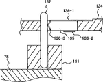
Figure 15 A is that explanation vibration wave linear motor and the 3rd moves the stereogram of the method for attachment of picture frame.
Figure 15 B only gets the amplification stereogram shown in its linking part.
Figure 16 A is the figure to arrow c direction 15B with the aid of pictures.
Figure 16 B is that the A-A ' of Figure 15 B vows pseudosection.
Embodiment
First embodiment
Below, with reference to the description of drawings embodiments of the present invention.Have, in the following description, first oscillator of recording and narrating in the summary of the present invention is made of for example oscillator 75 grades again, and second oscillator is made of for example oscillator 74 grades, and force application part constitutes by for example compressing spring 76 grades, and then, driven member is made of for example axle 78 grades.
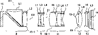
Figure 1A is the stereoscopic figure that the lens devices that has carried vibration wave linear motor of the present invention is shown, Figure 1B illustrates from the arrow a direction of Figure 1A to see that the A-A ' of the lens devices shown in Figure 1A vows the figure of the schematic configuration of each one of lens devices of looking section, shows the schematic configuration of each one of lens devices.
Have, Figure 1A shows the part of the circuit substrate 2 in the shell that is contained in agent sets such as video camera for example with lens devices 1 mutual group jointly again, and described circuit substrate 2 has the control circuit of driving of each one of this lens devices 1 of control.
This lens devices 1 with the second optical axis O2 shown in above-mentioned incident beam Figure 1B after the above-mentioned bending be directed to the end that is configured in lens devices 1 (among the figure tiltedly upper right side to), for example wait in the imaging apparatus 14 that constitutes the generation photographed images by CCD (chargecoupled device).
Shown in Figure 1B, have a plurality of lens in the inside of lens devices 1 along the second optical axis O2 to above-mentioned horizontal direction bending, comprising: the first fixed lens portion 8 is made of lens L1 and lens L2; The first mobile lens portion 9 is made of lens L3 and lens L4; The second mobile lens portion 11 is made of lens L5, lens L6 and lens L7; The 3rd mobile lens portion 12, L8 constitutes by lens; The second fixed lens portion 13, L9 constitutes by lens.
Then, imaging apparatus 14 in the terminal configuration of these lens groups.
The lens L1 and the prism of the above-mentioned first fixed lens portion 8 are integrated, make from above-mentioned photographic lens windowsill that camera axis O1 injects from the light beam of subject after 90 ° of horizontal directions reflection bendings roughly, along second optical axis O2 change light beam course.
In addition, lens L1 and lens L2 are maintained in the first fixed picture frame portion 15 jointly, are fixed in the lens devices 1.
In addition, the above-mentioned second fixed lens portion 13 remains in the second fixed picture frame portion 16, is fixed in the lens devices 1.
Using the length direction end that roughly becomes the metal framework described later of L font perpendicular to the section after the face cutting of the second optical axis O2, form the above-mentioned first fixed picture frame portion 15 and the second fixed picture frame portion 16 by ester moulding.
Between these the first fixed picture frame portions 15 and the second fixed picture frame portion 16, disposing and keep first of the above-mentioned first mobile lens portion 9 to move picture frame 17, keep second of the second mobile lens portion 11 to move picture frame 18, keep the 3rd of the 3rd mobile lens portion 12 to move picture frame 19.
Above-mentioned first moves picture frame 17, second moves picture frame 18 and the 3rd and moves picture frame 19, along the second optical axis O2, independent respectively and keeping the above-mentioned first mobile lens portion 9, the second mobile lens portion 11 and the 3rd mobile lens portion 12 movably by the bending of said lens L1 (below be called prism L1) approximate vertical.
For the focal length of the light beam that makes the subject of injecting along the second optical axis O2 of the optical system of this lens devices 1 changes, be provided with the above-mentioned first mobile lens portion 9 and the second mobile lens portion 11.
In other words, in order to regulate the zoom ratio of lens combination, first of these the first mobile lens portions 9 of maintenance and the second mobile lens portion 11 that be provided with moves picture frame 17 and second and moves picture frame 18.
In addition, in order to regulate the focus of above-mentioned light beam imaging on imaging apparatus 14, the 3rd mobile lens portion 12 is being set.
In other words, as the picture frame of the focusing usefulness that can on the second optical axis O2 direction, move freely, be provided with the 3rd of the 3rd mobile lens portion 12 of maintenance and move picture frame 19.
In addition, the position of the expression of 21 between the above-mentioned first mobile lens portion 9 and the second mobile lens portion 11 aperture.
In addition, in this lens unit, in order to make thickness up and down (, being actually the thickness of depth direction) as thin as a wafer as the lens unit of photography usefulness.
Promptly, cut the first fixed lens portion 8 that keeps comprising diameter bigger lens L2, L5, L8 respectively, the second mobile lens portion 11, respectively keep the first fixed picture frame portion 15, second of the 3rd mobile lens portion 12 move frame wall that picture frame portion the 18, the 3rd moves picture frame 19, for part or all of a side of the above-below direction of the second optical axis O2 (in the example of Figure 1B, the corresponding part in lens bottom with the below), form notch part 15-1,18-1,19-1.
Then, this cuts out the part weakened that lacks the frame wall behind the breach, about this part picture frame do not resemble first fixed picture frame 15 such have other reinforcing sections especially second, third move picture frame 18,19, on the frame wall that the folder second optical axis O2 and the opposed side of above-mentioned notch part are upside, the protuberance of giving prominence to the outside described later is being set.
In Figure 1B, second, third last side frame wall that moves picture frame 18,19 seems thick slightly, is because the section of raised part is shown.
In addition, move picture frame 19 about the 3rd, since about integral body thin and a little less than, so it is probably only insufficient by the reinforcement of raised part, therefore, be provided with protuberance 19-2, feasible lens body portion from the opposition side that is formed on notch part 19-1, bend into around the extraneous left side of effective sunlight that becomes lens L8, described notch part 19-1 is formed on the lower side of lens L8.
Fig. 2 is an exploded perspective view of seeing above-mentioned lens devices 1 from the top.
Fig. 3 makes said lens device 1 reverse the exploded perspective view of seeing from the below up and down.Have again, in above-mentioned Fig. 2 and Fig. 3, on the structure division identical with the structure of Figure 1A, B, the symbol that mark is identical with Figure 1A, B.
As above-mentioned Fig. 2 and shown in Figure 3, lens devices 1 has main fixed picture frame 22.
The inside and outside installation of this main fixed picture frame 22 and take in Fig. 2 and Fig. 3 shown in whole structural element the time, outer shape shown in whole Figure 1A that just forms apparatus main body, described apparatus main body is at opposed rectangular two interareas and be clipped in the structural element of having packed in the flat space in these two interareas.
Above-mentioned main fixed picture frame 22 has the metal framework 23a of at least one interarea that forms above-mentioned two interareas.In the structure of this lens devices 1, another interarea is being opened.
By from the metal framework 23a approximate right angle of a side interarea the metal framework 23b that is connected with, a side of the length direction in the folded flat space that becomes of the interarea that constitutes a side who forms by this metal framework 23a and the opposing party's interarea of opening.
In addition, a horizontal side transverse side of lower left (among Fig. 2, the Fig. 3 tiltedly) also is made of the metal framework 23c that the metal framework 23b with the metal framework 23a of above-mentioned interarea and length direction side generally perpendicularly is connected setting.
Like this, metal framework 23 (23a, 23b) constitute the framework of the L font that a side by an interarea and length direction forms with the rectangular section of length direction (also be aforesaid bending after the second optical axis O2 direction), become the framework that forms the ideal structure of rigidity by small quantity of material.
At the both ends of the length direction of this metal framework 23, forming respectively by the integrally formed fixedly forming section of injection molded and metal framework 23.
These two fixedly forming section be the first fixed picture frame portion 15 shown in Figure 1B and the second fixed picture frame portion 16.
Then, the first fixed picture frame portion 15 keeps and has fixedly omitted illustrated lens L2 among the prism L1 shown in Figure 1B and Fig. 2 and Fig. 3.
In addition, in the second fixed picture frame portion 16, keep and fixedly all omitted diagram among Fig. 2 and Fig. 3 but the lens L9 that illustrated among Figure 1B.
Between these the first fixed picture frame portions 15 and the second fixed picture frame portion 16,3 the mobile picture frames of configuration shown in Figure 1B (first move picture frame 17, second move picture frame 18 and the 3rd move picture frame 19).
On these 3 mobile picture frames and above-mentioned 2 fixed picture frames, forming binding agent and accumulating portion 24 (with reference to Fig. 2), around the binding agent of feasible maintenance respectively and fixed lens does not spill into.
This binding agent accumulate portion 24 be formed in the lens that are fixed around and the very little gap between the picture frame.
Have, the 3rd binding agent that moves the picture frame 19 and the second fixed picture frame portion 16 portion that accumulates ensconces the inside and cannot see in Fig. 2 and Fig. 3 again.In addition, the binding agent portion of accumulating of the first fixed picture frame portion 15 also cannot see in the drawings, but be arranged on and the corresponding part in side of the prism of lens L1 one on.
Before above-mentioned 3 mobile picture frames were installed, zoom was configured in axis cam 25 on the length direction side and the position that be close to the lateral parts of the first fixed picture frame portion 15 of open sides of main fixed picture frame 22.
Zoom has the large diameter part of the side face that forms the cam path that is provided with cam part and the small diameter part of establishing with aixs cylinder from the two ends of large diameter part 26 (26a, 26b) with axis cam 25, on the small diameter part 26a on the outstanding end that is arranged on imaging apparatus 14 opposition sides, fixedly installing gear 27.
In a single day zoom has been inserted through after a side the small diameter part 26a in bearing embedded hole 28 with axis cam 25, just one side is to the oblique right-hand introducing of figure, the opposing party's small diameter part 26b is embedded in the dead eye that is formed in the invisible in the drawings first fixed picture frame portion 15 in Tibetan on one side, one side's small diameter part 26a is combined with bearing 29 in bearing embedded hole 28, and described bearing embedded hole 28 is formed on the incorporate weld portion of metal framework 23c with the first fixed picture frame portion 15.
Like this, zoom just rotatably is supported in the first fixed picture frame portion 15 with axis cam 25.
At the jag of zoom with a side's of axis cam 25 small diameter part 26a, also forming the little protuberance of diameter 31, when a side small diameter part 26a combined with bearing 29, this protuberance 31 was outside upward outstanding from bearing 29.
By pushing this protuberance 31 by elastic leaf springs 32 elasticity, zoom just is positioned on the bearing up and down with axis cam 25, and stably keeps.
Elastic leaf springs 32 is made of following part: 3 32-1 of rhaeboscelia portion, separate a part from dimetric main part roughly by joint-cutting, and further bend its front end and form after the bending downwards to level; The stop section 32-2 that cuts main part central authorities and form; And, extend the 32-3 of spring portion of setting integratedly from main part.
On the other hand, in metal framework 23c side, with 3 rhaeboscelia portion corresponding positions of 32-1 of above-mentioned elastic leaf springs 32 on form 3 notch parts 33, in the substantial middle of being surrounded, forming the corresponding protuberance 34 of stop section 32-2 with above-mentioned elastic leaf springs 32 by these 3 notch parts 33.
If 3 32-1 of rhaeboscelia portion of elastic leaf springs 32 are combined on one side with 3 notch parts 33 of metal framework 23c, main part with elastic leaf springs 32 is pushed into metal framework 23c side on one side, then the front end by stop section 32-2 combines with the side face of protuberance 34, and elastic leaf springs 32 just is positioned in the outside of metal framework 23c.
Then, pushing zoom by the leading section elasticity of the 32-3 of this spring portion locatees with the protuberance 31 of axis cam 25.
Like this, zoom with the central shaft of axis cam 25 towards the length direction of main fixed picture frame 22, promptly with the parallel direction of the second optical axis O2, be configured in the prism L1 that is maintained in the first fixed picture frame portion 15 near, the part in being configured at least axially is configured to the side adjacency with prism L1.
Then, zoom is configured in the spatial portion (with reference to Fig. 3) of the summary triangle cylindricality that forms by the inclined-plane of the first fixed picture frame portion 15 of the reflecting surface dorsal part that keeps lens (prism) L1 with by metal framework 23c with motor unit 35, and its reduction gearing row 36 combine with the gear 27 of zoom with axis cam 25.
In the location decisions kong 39 and stop hole 41 of two place's retainer (with reference to Fig. 3) bolted on being formed on the first fixed picture frame portion 15, this zoom is fixed in the first fixed picture frame portion 15 with motor unit 35 gear shaft fixed part 37 and check plate fixed part 38.
Then above-mentioned, assembling diaphragm shutter unit 42 on main fixed picture frame 22.
Diaphragm shutter unit 42 (following with reference to Fig. 2) has diaphragm shutter portion 43 and rotary solenoid 44,45, described diaphragm shutter portion 43 has and limits catoptrical aperture and the shutter by light quantity that forms the second optical axis O2, and described rotary solenoid 44 and 45 mechanically drives the aperture and the shutter of this diaphragm shutter portion 43 respectively.
Diaphragm shutter portion 43 is configured on the position 21 of the aperture shown in Figure 1B, and two rotary solenoids 44 and 45 are configured in the below of zoom with axis cam 25.
In addition, below this diaphragm shutter unit 42, be used for moving vibration wave linear motor 46 and the magnetic sensor unit 47 that picture frame 19 is moved in driving the 3rd transversely disposing overlappingly side by side of main fixed picture frame 22.
Like this, vibration wave linear motor 46 is positioned on the extending direction of zoom with the axle of axis cam 25, and the shooting face of being configured in one side.
Magnetic sensor unit 47 (with reference to Fig. 3) has Magnetic Sensor seat 48, Magnetic Sensor 49, magnetic scale 51 and spring 52.
Have again, about above-mentioned vibration wave linear motor 46 and magnetic sensor unit 47, narration in further detail later on.
Disposed in this wise after above-mentioned each parts, assembling has been fixed first of the mobile lens portion 9,11 and 12 shown in Figure 1B (among Fig. 2 and Fig. 3 omit diagram) with binding agent respectively and has been moved picture frame 17, second and move picture frame 18 and the 3rd and move picture frame 19.
Remaining on these first moves picture frame 17, second and moves picture frame 18 and the 3rd and move the mobile lens portion 9,11 shown in Figure 1B on the picture frame 19 and each lens L3~L8 of 12, owing to be sectional side view in Figure 1B, so it is indeterminate, but about lens are cut for the lens devices shown in Figure 1A 1 after (about among Figure 1B), side face forms smooth side face up and down, if see lens, with regard to the shape of ovalize in the front.
Then, first, second, third periphery that moves the lens maintaining part of picture frame 17,18,19 keeps above-mentioned oval-shaped lens, corresponding, about the second optical axis O2 (in the lens devices 1 shown in Figure 1A about, in the lens unit shown in Figure 1B about) side face form the plane, like this, can realize being assembled in the slimming of the mobile picture frame in the lens devices 1.
In addition, second, third moves picture frame 18,19 in order to seek further slimming, cut to keep the picture frame of lens bottom (among Fig. 2 among the part of below, Fig. 3 the part of top), with the corresponding frame wall of smooth circumferential surface sections of lens bottom, form notch part 18-1, the 19-1 shown in Figure 1B, exposed the smooth circumferential surface sections at lens rear portions.
Have, above-mentioned notch part moves picture frame 18 for second and is arranged in Fig. 2 and the observable part of Fig. 3 again, but moves picture frame for the 3rd, and the inside that is hidden in the picture frame around remaining be can't see.
These first move picture frame 17, second and move picture frame 18 and the 3rd and move picture frame 19 (with reference to Fig. 2), have bearing portion 53 (53-1,53-2,53-3) respectively, and pilot hole 54 (54-1,54-2,54-3) is being set respectively in these bearing portions 53.
In addition, first move picture frame 17, second and move picture frame 18 and the 3rd and move on the picture frame 19, have U font notch part 55 (55-1,55-2,55-3) (with reference to Fig. 3) respectively with above-mentioned bearing portion 53 opposed ends at these.
In addition, on stage portion 58, paste and disposing light-reflecting components 59, described stage portion 58 is formed on the border of leading section outside 56 (with reference to Fig. 2) and the side surface part 57 that disposes the above-mentioned bearing 53-1 of portion, and to move the rearward end of the above-mentioned bearing 53-1 of portion of picture frame 17 and U font notch part 55-1 opposed with having first for described leading section.
In addition, with first move picture frame 17 the 53-1 of bearing portion laterally projecting setting integratedly part and extend upward integratedly on the part of setting with second 53-2 of bearing portion that moves picture frame 18, forming cam follower 61 (61-1,61-2) respectively.
In addition, laterally pasting light-reflecting components 62 on the side of upright setting integratedly with the 3rd 53-3 of bearing portion that moves picture frame 19.
In addition, moving picture frame 18 and the 3rd second moves on the picture frame 19, with the opposed leading section of the rearward end with above-mentioned bearing 53 (53-2, the 53-3) of portion and U font notch part 55 (55-2,55-3) outside, forming the protuberance 63 (63-2,63-3) of the reinforcement usefulness that illustrates among Figure 1B.
This protuberance 63 in order to make all slimmings of said apparatus, is cut out breach with the corresponding frame wall of the rear portion flat of oval lens for the picture frame intensity of strengthening having otch is provided with.
In addition, in the pilot hole 54 of above-mentioned 3 mobile picture frames, be inserted through two ends and be supported in first axis of guide 65 on the axis of guide support holes 64, axis of guide support holes 64 (64-1,64-2) be formed on the nearest bight of the open side separately of the first fixed picture frame portion 15 and the second fixed picture frame portion 16 and opening interarea on.
Like this, first, second and the 3rd move picture frame 17,18 and 19 (i.e. 3 mobile lens portions 9,11,12) and just be supported on the direction of the optical axis O2 shown in Figure 1B movably.
In addition, with the supporting first axis of guide 65 axis of guide support holes 64 (64-1,64-2) be formed on open side and the immediate bight of opening interarea on.
Like this, first axis of guide 65 is just in lens devices 1 main body that is formed by main fixed picture frame 22, as much as possible on the most external that neighbor configuration intersects with the interarea of opening in open side.
In this wise, by bearing portion 53 being bearing in as much as possible on first axis of guide 65 that contiguous most external is provided with, 3 mobile picture frames just are configured in narrow flat apparatus main body inside compactly.
When being inserted through this first axis of guide 65, move between the 53-2 of bearing portion of picture frame 18 at first 53-1 of bearing portion and second that moves picture frame 17, on first axis of guide 65 outside setting-in establishing compression spring 66 with the elastic force of pushing.
In addition, before above-mentioned 3 the mobile picture frames of assembling, configuration is by second axis of guide 68 at other 2 axis of guide support holes 67 (with reference to Fig. 3) supportings two ends, and these other 2 axis of guide support holes 67 are formed on and closing on side and the immediate position of opening interarea that metal framework 23b separately by the first fixed picture frame portion 15 and the second fixed picture frame portion 16 constitutes.
When above-mentioned 3 the mobile picture frames of assembling, with above-mentioned U font notch part 55 from laterally be entrenched on above-mentioned second axis of guide 68 and with being free to slide the supporting after, by being fulcrum with this second axis of guide 68, make each move picture frame and turn to the inside, be provided in first and move picture frame 17 and second and move cam follower 61 on the picture frame 18 and just be embedded into zoom with combination in the cam path of axis cam 25 with being free to slide.
That is, forming respectively and a plurality of picture frames (in this example, first moves picture frame 17 and second moves picture frame 18) corresponding cam (cam path of cam follower 61-1,61-2 combination) on axis cam 25 at zoom.
As described above, by cam follower 61 being embedded into zoom with in the cam path of axis cam 25, zoom moves picture frame 17 and second with axis cam 25 and first and moves picture frame 18 and combine with just being free to slide.
In addition, meanwhile, with first exterior upper portion 56 (with reference to Fig. 2) that moves picture frame 17 and the back side neighbor configuration that is forming the metal framework 23a of an interarea.
Then, be formed on second and move the protuberance 63 of reinforcement usefulness that picture frame 18 and the 3rd moves the leading section outside of picture frame 19, similarly be embedded in the peristome 69 that is formed on the metal framework 23a.
This peristome 69 is in order to avoid and second to move the mobile mobile lens that causes that picture frame 18 and the 3rd moves picture frame 19 (with reference to the interference between the moving of the lens L5 of Figure 1B~L8), promptly need to avoid the obstruction of moving, forming long peristome with the corresponding upper and lower of the shift motion of above-mentioned mobile lens to protuberance 63.
Afterwards, above-mentioned first axis of guide 65 is inserted through in the axis of guide support holes 64 at the pilot hole 54 of each bearing portion 53 that moves picture frame and both ends.
Like this, above-mentioned two axis of guides (65,68) just with zoom with axis cam 25 adjacency, and, with the axle abreast configuration of zoom with axis cam 25.
In this wise, because the shape shaft parts adjoin each other and configuration concurrently, therefore, can help the miniaturization of device integral body.
3 mobile picture frames (17,18,19) are by these two axis of guide supportings, be constrained to and can on optical axis O2 direction, slide, and, forbid rotation by a side the axis of guide around the opposing party's the axis of guide, determined to meet at right angles behind the position of direction, be configured in the main fixed picture frame 22 with optical axis O2.
In addition, by moving between the 53-2 of bearing portion of picture frame 18 at first 53-1 of bearing portion and second that moves picture frame 17, to compress outer being embedded on first axis of guide 65 of spring 66 and install, first moves picture frame 17 and second moves picture frame 18 and just is pushed to rightabout because of elastic force.
Like this, just will with zoom with each cam follower 61-1, the 61-2 of the cam path combination of axis cam 25 by being pressed on the opposite separately side of zoom with the cell wall of the cam path of axis cam 25.
Thereby, eliminate the play that produces between cam path when zoom drives with the rotation of axis cam 25 and the cam follower, like this, the position when correctly control moves to left and moves to right concerns.
In above-mentioned configuration, roughly walk abreast with axis cam 25 and adjacency ground configuration first axis of guide 65 with zoom.
Afterwards, installation imaging apparatus 14 below the second fixed picture frame portion 16.
In addition, with metal framework 23a be positioned at the one side on the first fixed picture frame portion 15 face, be installed on the first light-reflecting components 59 corresponding positions of moving on the picture frame 17, be provided with photoelectric sensor installing hole 71, configuration photoelectric sensor 72 in this photoelectric sensor installing hole 71.
This photoelectric sensor 72 is surveyed first absolute position of moving picture frame.
By detecting the shift position with the step number of the zoom motor that carries out stepper drive of motor unit 35, determine and this absolute position of detecting first displacement that moves picture frame apart by no illustrated control device counting zoom.
In addition, towards a side of the open side of the second fixed picture frame portion 16, be installed on the 3rd light-reflecting components 62 corresponding positions of moving on the picture frame 19, dispose other photoelectric sensors 73.
This photoelectric sensor 73 detects from being installed in the 3rd reverberation that moves the light-reflecting components 62 on the picture frame 19, surveys the 3rd absolute position of moving picture frame 19.
After having determined these absolute positions, utilize the rotation of zoom with positive and negative two directions of the motor in the motor unit 35, zoom just rotates on positive and negative two directions in the angle of prescribed limit with axis cam 25.
The first cam follower 61-1 and second that moves picture frame 17 moves the cam follower 61-2 of picture frame 18, and is arranged on this zoom and combines with 2 cam paths on the periphery of axis cam 25.
Like this, along with of the rotation of above-mentioned zoom with axis cam 25, first moves picture frame 17 and second moves picture frame 18 (i.e. the first mobile lens portion 9 and the second mobile lens portion 11) and just carries out away from moving with close along the direction of the second optical axis O2, the zoom that the image of the light beam that advances on optical axis O2 direction is dwindled or amplifies.
In addition, the diaphragm shutter unit 42 of diaphragm shutter portion 43 is disposed in utilization on the aperture position 21 between first, second mobile lens portion 9,11 shown in Figure 1B, when the beam moving route of advancing along optical axis O2 is cut-off control, utilize the light quantity of optical filter (ND filter) control to the shooting face.
Then, the mobile vibration wave linear motor that drives to the 3rd picture frame of the 3rd mobile lens portion 12 that keeps focusing usefulness is described.
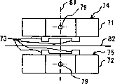
Fig. 4 A is the front view that the basic structure of the vibration wave linear motor that uses in this example is shown, and Fig. 4 B is the end view of Fig. 4 A.
Shown in Fig. 4 A, Fig. 4 B, the basic structure 70 of vibration wave linear motor at first has 2 oscillators 74,75, oscillator 74 and 75 is by 2 oscillator main bodys 71,72 up and down of rectangular shape and at least more than one is (in the example of figure, in the top oscillator main body 71 is 2, below oscillator main body 72 in is 1) driving contact site 73 (73-1,73-2,73-3) constitute, described driving contact site 73 with up and down on opposed of these 2 oscillator main bodys 71,72, respectively with oscillator main body 71,72 integratedly or with forming shape for lugs behind the other adhering components.
In addition, in the basic structure 70 of this vibration wave linear motor, up and down support unit 77 (77-1,77-2) and above oscillator 74 upper surface and and below the lower surface of oscillator 75 between, installed 2 compression springs 76 (76-1,76-2) up and down respectively, these 2 compression springs 76 have the elastic force of pushing of relatively suppressing both sides towards the relative portion of above-mentioned oscillator 74 and oscillator 75.
In addition, in the basic structure 70 of this vibration wave linear motor, has axle 78, this 78 contacts with 75 driving contact site 73 with the oscillator 74 that utilizes above-mentioned 2 compression springs urges, by above-mentioned 2 oscillators 74 and 75 clampings, simultaneously, length direction (being the direction towards the drawing the inside in Fig. 4 A, is the drawing left and right directions in Fig. 4 B) in the relative direction that is orthogonal to the relative portion of above-mentioned both sides is gone up by supporting with moving freely.
Since the elastic force of above-mentioned compression spring 76 be applied to oscillator main body 71 or 72 the joint portion that becomes vibration central portion 79 just above (or just down), therefore, the elastic force of compression spring 76 is distributed in the front and back (the figure left and right directions of Fig. 4 B) of the central authorities of oscillator main body 71 or 72 equably.
As later on explanatorily detailed, above-mentioned 3 drive contact sites 73 at least one carry out elliptic motion, above-mentioned axle 78 is relatively moved.
Not only in the basic structure shown in this, in the following various variation and the vibration wave linear motor after the actual assembled that illustrate, above-mentioned oscillator main body 71 and 72 also forms rectangular shape respectively, and above-mentioned 78 length that forms in its moving direction is longer than the length of each oscillator 74 and 75.
In addition, axle 78 is rectilinear forms, is made of hollow or solid bar-like member.Have, having illustrated among Fig. 4 A, Fig. 4 B and having made axle 78 is solid rod again.
In addition, this 78 end from bar-like member forms with same width to another end, and shown in Fig. 4 A, section is circular, that is, shown in Fig. 4 B, integral body forms cylindrical shape.
Certainly, axle 78 is not limited to cylindrical shape, does not have special illustrating, but also can be according to the variation of corresponding driving contact site, become have triangle, four jiaos, the post shapes of other polygonal sections.
Then, will drive the moving direction configuration of contact site 73 with 3 of this 78 crimping along axle 78.
These contact sites with axle 78 that drive contact site 73 have the section (be the U font, narrate later on about the V font) of U font or V font in Fig. 4 A.
In this wise, according to vibration wave linear motor of the present invention, owing to utilize 2 oscillators 74 and 75 driving shafts 78, and therefore, actuating force that can be big to the mobile conduction of axle 78.
In addition because a plurality of driving contact sites are along the contact of the moving direction of axle 78, therefore, can always keep for the moving direction of axle 78 certain towards.Therefore, can always keep best contact to come driving shaft 78.
In addition since can be in driving the contact-making surface of contact site 73 moving direction of restrictive axes 78, therefore, do not need the parts that move of the axis of guide 78, can cut down components number, help the realization of miniaturization and the reduction of cost.
In addition, as described above, because the elastic force of compression spring 76 is distributed in the front and back of the central authorities of oscillator main body 71 or 72 equably, therefore, drive contact site 73 and always can moving of fitted shaft 78 contact, therefore, can correctly effectively the actuating force of oscillator 74 and 75 be passed to axle 78 with axle 78.
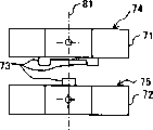
Fig. 5 A, Fig. 5 B are the figure that the section shape example that drives contact site 73 and contact-making surface axle 78 is shown, and Fig. 5 C, Fig. 5 D illustrate the figure to the configuration example of oscillator main body that drives contact site, and Fig. 5 E~Fig. 5 H is the figure that the structure example that drives contact site is shown.
Fig. 5 A is identical with the situation of Fig. 4 A, and the contact site with axle 78 that drives contact site 73 becomes the U i section.
Then, Fig. 5 B shows the situation that the contact site with axle 78 that drives contact site 73 becomes the V i section.
Drive contact site 73 in any case and all form and axle 78 contact-making surface semi-ring seize 78, like this, the shape set that just will drive contact site 73 is that feasible moving direction with axle 78 is limited on the above-mentioned moving direction.
In addition, Fig. 5 C shows on the basis of configuration, and oscillator 74 and 75 has 2 structures that drive contact site 73 jointly up and down.
In other words, oscillator 74 and 75 has a plurality of driving contact sites jointly up and down, whole symmetrical configuration is in the straight line 81 by central portion 79, described central portion becomes the above-mentioned oscillator main body 71 of two oscillators 74 and 75 and the joint portion of 72 vibration, simultaneously, this structure also is symmetrical in the central shaft 82 that has omitted illustrated axle 78 among Fig. 5 C.
In addition, Fig. 5 D is the configuration structure with the identical driving contact site 73 shown in Fig. 4 B.
In other words, between a plurality of driving contact sites 73 that are provided with on the superincumbent oscillator 74 of this structure arranged opposite below oscillator 75 at least one the driving contact site 73 that is provided with.
Also become the structure of straight line 81 of the central portion 79 of the joint portion that is symmetrical in the vibration by becoming oscillator main body 71 and 72 under this situation.
In any case, preferably oscillator 74 and 75 all is the structure of straight line 81 of the central portion 79 of the joint portion that becomes vibration by oscillator main body 71,72 that is symmetrical at least, or is symmetrical in the structure of the central shaft 82 of axle 78.
In addition, Fig. 5 C, Fig. 5 D, Fig. 5 G, Fig. 5 H form the binding type that utilizes flat part 84 to link mutually with a plurality of driving contact sites 73 and drive contact site 85, and, use the other parts different to constitute with oscillator main body 71 or 72.
These binding types driving contact sites 85 utilize bonding when assembling and oscillator main body 71 or 72 constitutes one.
Above-mentioned binding type drives side (being the side of length direction, the is horizontal side) unanimity that contact site 85 makes at least one end and oscillator main body 71 or 72 in Fig. 5 G, Fig. 5 H in Fig. 5 E, Fig. 5 F.
Particularly under the situation of Fig. 5 E, Fig. 5 F, be used in and link the size of flat part 84 that the binding type drives a plurality of driving contact sites 73 of contact site 85 and constitute consistent with 1 face of the bonding oscillator 71 (perhaps also can be 72) that should the binding type drives contact site 85.
As described above, drive the symmetric figure that is configured to of contact site 73, just do not need to consider directivity during assembling, therefore very convenient, the operating efficiency of assembling has improved.
Particularly shown in Fig. 5 C with axisymmetric shape because oscillator component can be general, therefore, to reducing cost effectively, in addition, the assembling of the directivity when not needing to consider bonding driving contact site becomes easily, the operating efficiency of assembling has also improved.
In addition, under the situation of any structure, all clamp axis 78 drives when arranged opposite a plurality of driving contact site 73, therefore, the actuating force of axle 78 has been improved.
In addition, contact site 73 will be configured to and the contact-making surface semi-ring seize 78 of axle 78 owing to will drive, therefore, even axle 78 fluctuates sometimes, because the directionality of encircling does not rock from side to side yet, in this wise, driving contact site 73 just is also used as driving shaft 78 and forbids this two aspect of axle 78 orientations of shaking to the left and right.
In addition, as link type and drive the contact site 85 ground, constitute driving contact site 73 with the other parts different with oscillator 71 or 72, therefore, in order to improve the performance that drives contact site and oscillator, can distinguish independent their material that changes variedly, because the degree of freedom and the performance of design improve jointly, therefore exploitation becomes easy.
In addition, drive contact site, and compare with oscillator is bonding behind a plurality of driving contact sites of dispersion processing, can cut down work manhours, help cutting down cost by being made as the binding type.
In addition, at least one end is consistent with the side of oscillator owing to binding type driving contact site is formed, therefore, easy and oscillator location, assembleability improves.
At this, the structure of the oscillator main body 71 (or 72, below identical) of above-mentioned vibration wave linear motor 70 is described.
Fig. 6 A is the front view of the oscillator main body 71 of above-mentioned vibration wave linear motor 70, Fig. 6 B is its end view, Fig. 6 C is the figure that electrode configuration oscillator main body 71 and piezoelectric patches shown in Fig. 6 A, Fig. 6 B is shown, and Fig. 6 D, Fig. 6 E are the figure that other structure example of 2 routine oscillator main bodys are shown.
Shown in Fig. 6 A, Fig. 6 B, oscillator main body 71 is made of piezoelectricity lamella 87 and elasticity lamella 89, and described piezoelectricity lamella 87 is made of stacked piezoelectric patches 86, and described elasticity lamella 89 is made of the flexure strip 88 of the below that is layered in the piezoelectricity lamella.
On the lower surface of the upper surface of piezoelectricity lamella 87 and elasticity lamella 89, pasting insulating trip 91 respectively.Have, this insulating trip 91 also can use the parts identical with the flexure strip 88 that originally is insulator again.
In addition, driving contact site 73 shown in Fig. 4 and Fig. 5 or binding type driving contact site 85 all is adjacent to the lateral surface separately of any one insulating trip 91.
The piezoelectricity lamella 87 of above-mentioned oscillator main body 71 constitutes the piezoelectricity body that forced vibration mainly is provided, and elasticity lamella 89 constitutes the portion that excites that excites specific vibration mode with the piezoelectricity body.
But,, just not necessarily need to excite portion if only just can excite the vibration mode of expectation with the piezoelectricity body.
The piezoelectric patches 86 of formation piezoelectricity lamella 87 only is whether to carry out the internal electrode shown in Fig. 6 C with the difference of the flexure strip 88 of elasticity lamella 89 and handles, and is the sheet component by the thin rectangle of same material formations such as for example PZT (lead zirconate titanate) originally.
Specifically, the shape that has for example long 10mm, wide 2.5mm, height (thickness of stacked direction) 80 μ m.
Have, the PZT material selection Qm value of using in this example is that 2000 so big hard based materials use again.Flexure strip too.
In addition, from the insulating trip 91 of clamping piezoelectricity lamella 87 and elasticity lamella 89 up and down, be identical PZT material, thickness is the shape of 40 μ m.
These insulating trips are and the piezoelectric patches identical materials, but electrode is not set, and therefore, are split pole states not, do not have piezoelectricity, thereby, have characteristic in fact as insulator.
, the only figure of electrode different two kind chip type piezoelectric elements that internal electrode is handled with having carried out constitute the piezoelectric patches 85 of piezoelectricity lamella 87.
These two kinds of piezoelectric patches 86 are the piezoelectric patches 86m that has formed A+ internal electrode paper tinsel 94 and B-internal electrode paper tinsel 95 about a side is divided into behind two sides on roughly whole shown in Fig. 6 C.
On above-mentioned A+ internal electrode paper tinsel 94 and B-internal electrode paper tinsel 95, respectively on position,, formed highlightedly and be used for and outside terminal 94-1 and the terminal 95-1 that is connected to the side of piezoelectric patches 86m near two ends, the left and right sides.
On the other hand, be the piezoelectric patches 86n that roughly on whole, has formed A-internal electrode paper tinsel 96 and B+ internal electrode paper tinsel 97 about being divided into equally behind two sides.
On above-mentioned A-internal electrode paper tinsel 96 and B+ internal electrode paper tinsel 97, respectively about on the position near central authorities, formed to same as described above one of piezoelectric patches 86n side-prominently and to be used for the terminal 96-1 and the terminal 97-1 that are connected with the outside.
Above-mentioned internal electrode paper tinsel uses silver palladium alloy or silver as its electrode material, for example utilizes evaporation and photoetching method technology, forms the shape of thick 4 μ m.
In this example, replace overlapping each 24 and add up to 48 these two kinds of piezoelectric patches 86m and 86n, constitute piezoelectricity lamella 87 as lamella.
In this wise, in the pars intermedia of removing topmost and foot, constituted the internal electrode that the piezoelectric patches 86 (86n or 86m) that self formed a slice internal electrode paper tinsel and two sides to the piezoelectric patches 86 that is connected with self (86m or 86n) apply the voltage of opposite potential.
In addition, outside terminal 94-1,95-1,96-1 and the 97-1 that connects usefulness from above-mentioned A+ internal electrode paper tinsel 94, A-internal electrode paper tinsel 96, B+ internal electrode paper tinsel 97, B-internal electrode paper tinsel 95 respectively to a side-prominent formation of piezoelectric patches 86 (86m, 86n).
Above-mentioned outside connects terminal 94-1,95-1,96-1 and the 97-1 of usefulness in a side of the oscillator main body 71 shown in Fig. 6 A, is connected with A+ electrode that sintering silver constitutes respectively that outside terminal 98, A-electrode connect outside terminal 99, the B+ electrode connects outside terminal 101 and is connected outside terminal 102 connections with the B-electrode.
An above-mentioned side's A+ electrode connection outside terminal 98 is connected outside terminal 99 and constitutes A phase electrode with the A-electrode, the opposing party's B+ electrode connection outside terminal 101 is connected outside terminal 102 and constitutes B phase electrode with the B-electrode.
Have, under this situation, the A-electrode connects outside terminal 99 and is connected outside terminal 102 with the B-electrode and constitutes A and B ground (GND) connection usefulness mutually respectively again, therefore, under this situation, also can constitute with same lead-in wire etc. and is connected, and becomes on electric idiostatic.
Connect outside terminal by these A with B electrode mutually, particularly from there not being illustrated drive circuit, apply voltage to piezoelectricity lamella 87, ultrasonic elliptically vibrating described later takes place in oscillator main body 71.
Have, the size of the oscillator main body 71 in this example for example is that length direction is of a size of 10mm again, and the horizontal 2mm that is of a size of highly is the shape of 2.5mm then.
As shown in Figure 6A, on this oscillator main body 71, above-mentioned A phase electrode and B mutually electrode roughly in the middle of, be on the position of central portion 79 of the joint portion that becomes vibration shown in Fig. 4 B, Fig. 5 C, Fig. 5 D, Fig. 5 E and Fig. 5 G, formed pin parts installing hole 103.About this pin parts installing hole 103, narrate later on.
In addition, as the piezoelectricity body, not necessarily the piezoelectricity lamella 87, also can be as the lower part.
For example, Fig. 6 D shows the piezoelectricity body, and the piezoelectrics 105 that adhesive bond is made of stacked piezoelectrics or piezoelectric element, the main portion 106 of oscillator main body, the oscillator main element 107 that are made of for example brass material are as the oscillator main body.
Under this situation, main portion 106 of oscillator main body and oscillator main element 107 constitute the portion that excites.
In addition, Fig. 6 E shows the structure of bonding thin veneer piezoelectrics 109 on the elastomer portions 108 of for example brass material of rectangular shape.
Under this situation, elastomer portions 108 constitutes the portion that excites.
When these parts bonding, give sufficient pressing force and carry out bondingly, this is particularly important in order to improve transfer of vibration efficient.
Fig. 7 A, Fig. 7 B be pattern ground explanation in said structure, the stereogram of the ultrasonic elliptically vibrating of the oscillator main body 71 of the vibration wave linear motor 70 by coming vibratory drive to electrode application voltage.
Fig. 7 C is only with the figure shown in the outline line of the oscillator main body of the secondary flexural vibrations of understanding Fig. 7 B easily.
At first, if to the A phase electrode 98,99 of the oscillator main body 71 shown in Fig. 6 A and B mutually electrode 101,102 apply near the resonance frequency alternating voltage with same-phase, just shown in Fig. 7 A, on oscillator main body 71, excite the one-level length direction vibration that constitutes by resting position 111 and resonant length direction vibration position 112.
Under this situation, oscillator main body 71 is flexible to length direction, and the size up and down of central portion is flexible simultaneously.
In addition, in Fig. 6 A, if to above-mentioned A phase electrode 98,99 and B mutually electrode 101,102 apply near the resonance frequency alternating voltage with antiphase, just shown in Fig. 7 B, on oscillator main body 71, excite the secondary flexural vibrations that constitute by the resting position 113 and the flexural vibrations position 114 of resonating.
These vibrations are contemplated to by using limited factors method to carry out computer analyzing, but the result that actual ultrasonic vibration is measured has also confirmed these anticipations.
Have again, in Fig. 7 C, except resting position 113 and resonance flexural vibrations position 114, show 2 actions that drive contact sites under the situation of structure of driving contact site 73-1 on the oscillator main body 71 that is configured in shown in Fig. 4 B and 73-2 on top.
In addition, also not shown among the figure so far, but in Fig. 7 C, show 22 actions that drive contact sites that drive under the situation at length direction two ends that contact sites are configured in the oscillator main body in the bottom.
In this wise, for from oscillator to driven member (axle) transferring power efficiently, drive the best fixed configurations of contact site on the highest position of the vibration with the driven member relative direction of oscillator or near it.
In addition, the pin parts 115 that are installed in the pin parts installing hole 103 have been shown among Fig. 7 A, Fig. 7 B, described pin parts installing hole 103 is shown in Fig. 6 A, Fig. 6 D and Fig. 6 E, is formed on the position of central portion 79 of the joint portion that becomes vibration shown in Fig. 7 C.
Have again, relevant with resonance frequency in the present embodiment, the resonance frequency of crooked secondary vibration is designed to low a few percent (being contemplated to be about 3%) of resonance frequency than the vibration of length direction one-level.
By such structure, the output characteristic as vibration wave linear motor is improved significantly.
Below, if to the A phase electrode 98,99 of oscillator main body 71 and B mutually electrode 101,102 apply near the resonance frequency that phase place only differs pi/2 alternating voltage, just can drive on the position of contact sites 73 2 of the length direction two ends that are configured in the oscillator main body shown in Fig. 7 C of oscillator main body 71 and be configured in the end shown in Fig. 7 C of oscillator main body 72 and central authorities roughly in the middle of the position of 2 driving contact sites 73 on observe elliptical vibration.
Under this situation, the direction of rotation of the locational elliptical vibration that is caused by ultrasonic vibration that is in driving contact site 73 on the bottom surface of oscillator main body 71 is with the direction of rotation opposite (with reference to Fig. 8) of the locational elliptical vibration that is caused by ultrasonic vibration of the top driving contact site 73 that is configured in vibration main body 72.
Fig. 8 A, 8B be pattern the elliptical vibration of driving contact site of the oscillator when near the alternating voltage that has applied the resonance frequency that phase place only differs pi/2 is shown.
Have, the configuration of the driving contact site 73 of the binding type driving contact site 85 shown in Fig. 8 A, Fig. 8 B is different up and down, drives contact site 85 but show the binding type with jack per line again.In addition, driving under the situation that contact site 73 is respectively independent driving contact site, below the action of Shuo Ming elliptical vibration is identical.
Fig. 8 A shows the work of situation of the phase advance pi/2 of the alternating voltage that A phase electrode 98,99 applies than B phase electrode 101,102.
Under this situation, the driving contact site 73 of the bottom surface of oscillator main body 71 carries out clockwise rotation, and on the other hand, the top driving contact site 73 of vibration main body 72 carries out anticlockwise rotation.
Then, Fig. 8 B shows the work of situation of the phase lag pi/2 of the alternating voltage that A phase electrode 98,99 applies than B phase electrode 101,102.
Under this situation, the driving contact site 73 of the bottom surface of oscillator main body 71 carries out anticlockwise rotation, and on the other hand, the top driving contact site 73 of oscillator main body 72 carries out clockwise rotation.
In this wise, preferably the driving contact site of identical oscillator is configured on the position of equidirectional rotation, and the driving contact site of the oscillator of opposition side is configured on the position of rotation round about.
Like this, just can take out actuating force the most efficiently for axle 78.
Promptly, length direction vibration and the synthetic elliptical vibration of flexural vibrations by above-mentioned oscillator main body 71 and 72, drive contact site 73 by 4 and act on the axle 78, axle 78 is according to the guiding of the contact-making surface that respectively drives contact site 73 of oscillator main body 71 and 72, at the figure shown in Fig. 4 A, the B
*The drawing of A is direction and figure inwards
*Drawing left and right directions advance and retreat among the B move.
The operation principle of the vibration wave linear motor among the present invention that Here it is.
Have again, in the present embodiment, the piezoelectricity body by the A that sets A phase electrode 98,99 mutually with set B and constitute at two places of the B phase of electrode 101,102 mutually, but the piezoelectricity body is not limited to two places, as long as can cause length direction vibration and flexural vibrations, also can be more than 3 places.
In addition, in this example,, therefore, under these circumstances, obtain above-mentioned actuating force by length direction vibration and flexural vibrations because oscillator main body 71 is rectangular shapes roughly.
But if can obtain actuating force after the driving contact site causes elliptical vibration, oscillator can be other shapes also just.
In addition, even excite the pattern of the frequency of one or more identical or integral multiples simultaneously, also can access identical oscillating movement.
In addition, expectation drives contact site and is configured in as vibration wave linear motor and can obtains on the optional position of output characteristic of highest ranking, that is, and and on the position of vibration main body 71 or 72 the ultrasonic elliptically vibrating that carries out highest ranking.
But, usually, configuration driven contact site like this, make it carry out elliptical vibration, but in order to become drive source, at least in more than one driving contact site, cause elliptical vibration, make the summation of the caused actuating force of vibration that on the position of whole driving contact sites, produces be not equal to 0 at least.
In addition, also can not need on the position of whole driving contact sites, cause elliptic motion, under the situation that causes single vibration or vibration in the other direction, do not become 0 from each summation that drives the actuating force of contact site, and the actuating force that becomes to some directions gets final product.
In any case, by the allocation position of suitably setting electrode, the allocation position that applies regularly, drives contact site of alternating voltage, can both use 2 oscillators up and down, with the input voltage driving shaft 78 of irreducible minimum.
In addition, in the example of the oscillator 71 shown in Fig. 8 A, Fig. 8 B, drive the length direction both ends that contact site 73 is formed on oscillator main body 71, but under such situation, driven member is that the length of the moving direction of the axle 78 shown in Fig. 4 waits must form longlyer than the maximum configured length of a plurality of driving contact sites (being 2) of oscillator in the example of Fig. 8.
Fig. 9 A, Fig. 9 B, Figure 10 A, Figure 10 B, Figure 11 A, Figure 11 B, Figure 12 A and Figure 12 B are respectively the front view and the end views of various variation that the basic structure of vibration wave linear motor is shown.
Have, in these figure, mark and Fig. 4 A, number that Fig. 4 B is identical illustrate in the structure division identical with the structure shown in Fig. 4 A, Fig. 4 B again.
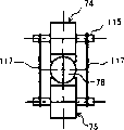
At first, in Fig. 9 A, Fig. 9 B, respectively from 71,72 configurations of both sides folders oscillator, section is the paddy of V word of joint portion 116-1 of V font of the application of force bonded block 116 of コ font, combine with the two ends of pin parts 115 in the pin parts installing hole that is inserted into oscillator 71 and 72 (with reference to the pin parts installing hole 103 of Fig. 6 A, Fig. 6 D, Fig. 6 E) (also with reference to Fig. 7 A, Fig. 7 B pin parts 115).
At this, compression spring 76 (76-1,76-2) does not directly push oscillator 71 and 72 shown in Fig. 4 A, Fig. 4 B, and with above-mentioned application of force bonded block 116 butts, like this, just by application of force bonded block 116 and pin parts 115 pushing oscillators 71 and 72.
In this wise, owing to, therefore,, just can push oscillators to axle 78 simply with the structure of the displacement that resonance produced that does not hinder oscillator by being inserted through the pin parts 115 pushing oscillators 71 and 72 in the central portion 79 of the joint portion that becomes vibration of oscillator 71 or 72.
In addition, because pin parts 115 do not have the central part pushing oscillator of displacement at it, therefore, can be equably to axle pushing oscillator, like this, driving shaft 78 stably just.This dispose as illustrated in fig. 8 a plurality of driving contact sites in the situation of axle pushing too.
Figure 10 A, Figure 10 B are fixed on a side's (being oscillator 72 in the example of Figure 10) of the oscillator 71 in the structure of Fig. 9 A, Fig. 9 B or 72 application of force bonded block 116 on the support unit 77 (being 77-2 in the example of Figure 10), only push the opposing party's oscillator (being oscillator 71 in the example of Figure 10) by application of force bonded block 116 and pin parts 115.
Do like this, just kept identical functions, do not had a part of force application part, can make whole structure miniaturization with the situation of Fig. 9 A, Fig. 9 B.
Figure 11 A, Figure 11 B show the support unit 77 of removal shown in Fig. 9,10 and the accessory of the such auxiliary pushing of application of force bonded block 116, only with the structure of 2 oscillators of force application part pushing.
That is, stride across the two ends of the oscillator 74 and 75 the pin parts 115 of clamp axis 78 respectively, hanged up the wire spring 117 of rhombus with traction elastic force.Like this, just can easily suppress 2 oscillators 74 and 75 to axle 78.
This structure can be simplified the control of suppressing to axle 78 of 2 oscillators 74 and 75, does not need complicated control, vibration wave linear motor can be constituted assembly, therefore, can help whole miniaturization.
In addition, since very little just to the elastic force of 2 oscillators, therefore, can the miniaturization force application part.In addition, owing to can only come modularization, therefore, be axle for driven member with oscillator and axle and force application part, the degree of freedom of the displacement of oscillator increases, and can freely drive.
The wire spring 117 of the rhombus of the structure of Figure 12 A, Figure 12 B replacement Figure 11 A, Figure 11 B, the helical spring 118 that has the traction elastic force has equally been hanged up at the two ends that stride across the pin parts 115 of oscillator 74 and 75 respectively.This structure is only changed the wire spring 117 and the helical spring 118 of rhombus, and the situation with Figure 11 A, Figure 11 B aspect function and effect is identical.
Figure 13 A is other other routine front views that the basic structure of vibration wave linear motor is shown.Figure 13 B is its end view.Figure 13 C is the end view of opposite side.
Structure shown in Figure 13 A, Figure 13 B, Figure 13 C is Fig. 9 A, Fig. 9 B and application of force bonded block 116 shown in Figure 10 A, Figure 10 B and identical with compression spring 76 etc. force application part 119 structure after integrated of pushing.
That is, in Fig. 9 A, Fig. 9 B and Figure 10 A, Figure 10 B, be the part of application of force bonded block 116, in Figure 13 A, Figure 13 B, Figure 13 C, become the joint portion 119-1 that pushes force application part 119.
This pushes force application part 119 respectively shown in arrow a and arrow a ', free end up and down shown in Figure 13 B has the elastic force of pushing to the inside, that is, for example, joint portion 119-1 up and down pushes the elastic force of the pin parts 115 of oscillator 74 and 75 respectively from the top down and from bottom to top.
In this wise, the force application part that pushes oscillator 74 and 75 is made of force application parts such as tension spring, compression spring, leaf springs, and constituting at driven member is to oscillator 74 and the certain elastic force of 75 sustainable supplies in the moving of axle 78.
Below, about the advance and retreat locomotivity of the axle 78 that takes out oscillator 74 in the vibration wave linear motor that is made of aforesaid basic structure and 75 elliptical vibration driving contact site 73, shown in Fig. 8 A, Fig. 8 B, the structure that moves the mobile actuating force of picture frame 19 as the 3rd shown in Fig. 1 to Fig. 3 describes.
Figure 14 A is the exploded perspective view of the vibration wave linear motor that uses in this example, and Figure 14 B is the stereogram of the state after it is shown assembles.
Shown in Figure 14 A, Figure 14 B, vibration wave linear motor 120 at first has oscillator 74 and 75, and described oscillator 74 and 75 oscillator main body 71,72 and a plurality of (being respectively 2 in the example of Figure 14 A, Figure 14 B) by the rectangular shape shown in Fig. 9 to Figure 13 drive contact site 73 formations.
Central portion in the joint portion that becomes vibration of these oscillators 74 and 75 is inserted through pin parts 115 respectively, and its two ends are outstanding to the outside from the two sides of oscillator 74 and 75 respectively.
In addition, has frame 122.Frame 122 is housed in above-mentioned oscillator 74 and 75 in the upper and lower, forbids these oscillators 74 and 75 moving to length direction (from the oblique lower-left of Figure 14 A, Figure 14 B to tiltedly upper right direction).
In addition, on the two sides of the length direction of frame 122, formed axle inserting hole 121-1, the 121-2 that is inserted through axle 78.
Between the oscillator 74 and 75 in the upper and lower that is housed in frame 122, the axle inserting hole 121-1 that has been inserted through frame 122, the axle 78 of 121-2 have been installed.
Application of force bonded block 123-1,123-2 have been made up from the upper and lower that encircles frame 122 up and down of above-mentioned frame 122.
On an end (the oblique upper right side of Figure 14 A, Figure 14 B is to the end) of the length direction of application of force bonded block 123-1,123-2, fixed pin holes 124-1,124-2 have been formed respectively, corresponding with these fixed pin holes, also formed fixed pin holes 125-1,125-2 respectively in an end of the length direction of the upper and lower of frame 122.
Be inserted through among the fixed pin holes 124-1 of application of force bonded block 123-1 above these and the fixed pin holes 125-1 on frame 122 tops and link latch 126-1.
126-1 is a fulcrum with this binding latch, and application of force bonded block 123-1 freedom joltily is fixed on the upper end of frame 122.
On the other hand, below the fixed pin holes 124-2 of application of force bonded block 123-2 and the fixed pin holes 125-2 of frame 122 bottoms in be inserted through and link latch 126-2.
126-2 is a fulcrum with this binding latch, and application of force bonded block 123-2 freedom joltily is fixed on the bottom of frame 122.
In addition, on another end (the oblique lower left of Figure 14 A, Figure 14 B is to the end) of the length direction of application of force bonded block 123-1,123-2, formed respectively and suppressed with pin-and-hole 127-1,127-2.
In these suppress with pin-and-hole 127-1,127-2, be inserted through respectively to suppress and use in conjunction with pin 128-1,128-2.
Using in conjunction with outstanding both ends, the outside of pin 128-1 to suppressing, the locking groove 128-1a, the 128-1b that cut along circumference have been formed respectively, use in conjunction with outstanding both ends, the outside of pin 128-2 suppressing, also formed the locking groove 128-2a, the 128-2b that cut along circumference respectively to another.
Clearly do not illustrate among Figure 14 B, but use in conjunction with the locking groove 128-1a of the front side of pin 128-1 and suppress among the locking groove 128-2a that uses in conjunction with the front side of pin 128-2, fixing the two ends of a helical spring 129-1 with traction elastic force respectively above-mentioned suppressing.
In addition, use in conjunction with the locking groove 128-1b of the dorsal part of pin 128-1 and suppress among the locking groove 128-2b (in Figure 14 B, all be hidden in the miscellaneous part and cannot see) that uses in conjunction with the dorsal part of pin 128-2 above-mentioned suppressing, fixing the two ends of another helical spring 129-2 with traction elastic force respectively.
Like this, top application of force bonded block 123-1 is that fulcrum pushes downwards all to link latch 126-1 just.
Then, this application of force bonded block 123-1-1 combines with the pin parts 115 of top oscillator 74, pushes oscillator 74 downwards, and following application of force bonded block 123-2 is that fulcrum pushes all upward to link latch 126-2.
Then, the joint portion 123-2-1 of application of force bonded block 123-2 combines with the pin parts 115 of following oscillator 75, pushes oscillator 75 upward.
Pushed by these oscillators 74 and oscillator 75 and an end of the axle 78 of clamping (the oblique upper right side of Figure 14 A, B to end) hold-down nut 131.
In this nut 131, with the axle of axle 78 at right angles and go up fixed installation towards the direction of level (be tiltedly upper left towards) drive and combine pin 132 in Figure 14 A, Figure 14 B.Have, the long front end that extends that drives in conjunction with pin 132 is hidden in the miscellaneous part in Figure 14 B and cannot see again.
Along with by oscillator 74 and oscillator 75 to length direction advance and retreat driving shaft 78, this driving is just moved along with this action of 78 in conjunction with pin 132.
Figure 15 A is that explanation vibration wave linear motor 120 and the 3rd moves the stereogram of the method for attachment of picture frame 19, and Figure 15 B only gets the amplification stereogram that its linking part is represented.
Have, Figure 15 A sees that in Fig. 3 vibration wave linear motor 46 (being 120) and the 3rd moves the figure of picture frame 19 in Figure 15 A again.
In addition, Figure 15 A is for easy understanding, makes the driving in the nut 131 of the oblique upper left one side-prominent end that is arranged on axle 78 break away from from nut 131 and represent towards its outstanding side direction that is provided with in conjunction with pin 132.
Figure 16 A is the figure to arrow c direction 15B with the aid of pictures, and Figure 16 B is that the A-A ' of Figure 15 B vows pseudosection.Have again, in Figure 16 B, also combine the section that pin 132 shows axle 78 and nut 131 jointly with driving.
Shown in Figure 15 A, the 3rd moves picture frame 19 by the picture frame main body 133 that keeps the 3rd mobile lens portion 12 and the 53-3 of bearing portion, from outstanding the constituting in conjunction with protuberance 134 of being provided with of the 53-3 of this bearing portion downwards.
In the substantial middle portion in conjunction with protuberance 134, the direction parallel to the moving direction that moves along optical axis O2 with picture frame main body 133 wearing long slotted hole 135.
In this slotted hole 135 (following) with reference to Figure 16 A, Figure 16 B, from the rear side of figure in conjunction with will move driving that output takes out usefulness in conjunction with pin 132 suppress with the 3rd leaf spring 136 that moves on the place (combining the slotted hole 135 of protuberance 134) of picture frame 19 butts.
Leaf spring 136 by the 136-1 of planar main body portion, from the below of this main part 136-1 forward with the fixed part 136-2 of two sections of top bendings, laterally constitute towards the elastic portion 136-3 of the place ahead bending from the left side of main part 136-1.
This leaf spring 136 is fixed in conjunction with on the protuberance 134, make this fixed part 136-2 from dorsal part around going into clamping the 3rd the bottom that is forming slotted hole 135 of moving picture frame 19, ground in conjunction with protuberance 134.
Like this, the main part 136-1 of leaf spring 136 and the dorsal part opening surface of slotted hole 135 are combined closely, elastic portion 136-3 is inserted into assigned position in the slotted hole 135 from dorsal part on.
Have again, between the left part of elastic portion 136-3 and slotted hole 135, forming only to be inserted through to move and exporting the gap of taking out with driving in conjunction with pin 132.
In addition, move between the side 133-1 and face of dorsal part of picture frame main body 133 of picture frame 19 the 3rd in conjunction with the front face side of protuberance 134, forming the space that just in time disposes flexible substrate (aftermentioned), the oscillator main body 71 of described flexible substrate and vibration wave linear motor 120 is connected with the A+ electrode shown in Fig. 6 of 72 that outside terminal 98, A-electrode connect outside terminal 99, the B+ electrode connects outside terminal 101 and is connected outside terminal 102 connections with the B-electrode.
When having disposed vibration wave linear motor 120 in this space, shown in Figure 15 B, it moves the output taking-up and is inserted through in the gap that forms between the left part of elastic portion 136-3 and slotted hole 135 in conjunction with pin 132 with driving.
Because this combination, move driving that output takes out usefulness in conjunction with pin 132 the moving that in slotted hole 135, be under an embargo to the second optical axis O2 direction.
On the other hand, on the metal framework 23a shown in the Fig. 2 shown in frame 122 fixed configurations shown in Figure 14 B of vibration wave linear motor 120 are omitted in Figure 15 A.
Like this, drive in conjunction with pin 132 just can be verily with spools 78 pass to the 3rd to the second optical axis O2 direction mobile and move picture frame 19 of vibration wave linear motor 120.
In addition, on the other hand, the permission driving has play in moving up and down in conjunction with pin 132 in above-mentioned combination.Utilize this play, absorb tiltedly shaking of above-below direction oscillator main body 71,72 and axle 78, that with the pin parts 115 of oscillator main body 71 or 72 be the center etc.
In addition, like this, move driving that output takes out usefulness in conjunction with pin 132 make as described above axle 78 to the second optical axis O2 move move picture frame 19 towards correctly passing to the 3rd with power, on the other hand, be subjected to axle 78 move up and down that influences by moving up and down of generations such as elliptical vibration of oscillator main body 71 and 72, in slotted hole 135, move up and down middle absorption, do not pass to the 3rd and move picture frame 19.
In this wise, in this example, move in the binding of 19 on picture frame at axle 78 and the 3rd, be fixed on the axle 78 by nut 131 on the one hand, on the other hand, utilize the elastic force of leaf spring 136, moving on the place (combining the slotted hole 135 of protuberance 134) of the picture frame butt of picture frame 19 with the 3rd, the mobile output that forms butt is only taken out with the connecting state that drives in conjunction with pin 132, like this, just makes the locomotivity (actuating force) of axle 78 pass to the 3rd and moves moving of picture frame 19.
In this wise, driving is vibration wave linear motor 120 to be carried under the situation on electronic equipment or the device etc. in conjunction with pin 132, is used for the mobile actuating force of the axle 78 mobile drive transmission member to outside (being moved in the mobile driving mechanism electronic equipment in, the device driving thing) transmission.
And say, in above-mentioned Fig. 4 A, Fig. 4 B, illustrated that 78 and 2 oscillators 74,75 of axle of vibration wave linear motor 70 in this example (or 120, below identical) have the relation that relatively moves.
If describe with Figure 15 A, then under the situation of Figure 15 A, the axle 78 that utilization is just moved with respect to fixing frame 122, moving picture frame 19 in conjunction with pin 132 with the 3rd of these 78 bindings by nut 131 and driving just moves, but for example with the end, front and back of the moving direction of the force application part clamp axis 78 that does not hinder axle 78 vibration, this force application part is fixed on the metal framework 23a, will be formed on the 3rd with the fixedly connected portion of frame 122 and moves on the suitable position of picture frame 19.
Do like this, axle 78 becomes fixed configurations, and oscillator 74 and 75 is that frame 122 just just moves with respect to this axle 78, that is, with frame 122 fixedly connected the 3rd to move picture frame 19 just mobile.
Also can constitute in this wise, thereby, have the relation that relatively moves about axle 78 and 2 oscillators 74 and 75 and be illustrated.
In any case, according to vibration wave linear motor of the present invention, owing to drive driven member with 2 oscillators, therefore, it is big to drive thrust, can realize high efficiency driving.
In addition, be U font or V font owing to drive the section of the contact site of contact site and driven member, therefore, the moving direction of enough this contact site restriction driven members of energy, thereby, do not need guiding parts, components number can be cut down, like this, the realization of miniaturization and the reduction of cost can be helped.
In addition, owing to cooperating moving of driven member, oscillator also shakes, therefore, drive contact site and always can contact with driven member, thereby, can correctly efficiently the actuating force of oscillator be passed to driven member, from this respect, also can realize high efficiency driving.
In addition,, therefore, can individually change material variedly, can easily improve the performance that also comprises the life-span for the performance that improves oscillator main body or driving contact site owing to constitute the oscillator main body and drive contact site with other parts.
In addition,, just can directly drive lens picture frame etc. and carry out the parts that straight line moves, can reduce mechanical loss, can realize high efficiency driving by Linear Driving.
In addition, the picture frame of video camera during as driven member, is being utilized Linear Driving, the lens picture frame can be directly driven, for example, the focusing time can be shortened the picture frame of focus lens, also can tackle user's the action of photography fast, the action of the photography of answer up easily.
In addition, owing to can utilize Linear Driving directly to drive picture frame, therefore, can reduce mechanical loss, the extension fixture life-span.
Claims (20)
1, a kind of vibration wave linear motor is characterized in that, has:
First oscillator comprises the piezoelectricity body and constitutes, and has a driving contact site that vibrates by the voltage that applies regulation at least;
Second oscillator comprises the piezoelectricity body and constitutes, and has a plurality of driving contact sites that vibrate by the voltage that applies regulation;
Force application part, the opposed portion towards both sides relatively pushes with above-mentioned first oscillator and above-mentioned second oscillator; And
Driven member, with contact with the driving contact site of above-mentioned second oscillator by above-mentioned first of this force application part pushing, and by the above-mentioned first and second oscillator clampings, and, with the length direction of the relative direction quadrature of above-mentioned opposed portion on, move freely with respect to above-mentioned first and second oscillators and to be supported;
In the above-mentioned driving contact site of above-mentioned first or second oscillator at least one carried out elliptic motion, and above-mentioned driven member is relatively moved.
2, vibration wave linear motor as claimed in claim 1 is characterized in that, above-mentioned driven member is made of the hollow of rectilinear form or solid bar-like member.
3, vibration wave linear motor as claimed in claim 1 is characterized in that, the length of above-mentioned driven member on its moving direction is longer than the length of above-mentioned each oscillator.
4, vibration wave linear motor as claimed in claim 1 is characterized in that, above-mentioned driven member forms longer than the maximum configured length of above-mentioned a plurality of driving contact sites of above-mentioned second oscillator in the length of its moving direction.
5, vibration wave linear motor as claimed in claim 2 is characterized in that, above-mentioned driven member has to drive at an end of above-mentioned bar-like member and transmits the joint portion, from an end of above-mentioned bar-like member to another end with identical width formation.
6, vibration wave linear motor as claimed in claim 1 is characterized in that, the shape set of above-mentioned driving contact site is become, and limits the moving direction of this driven member with the contact-making surface of above-mentioned driven member.
7, vibration wave linear motor as claimed in claim 1 is characterized in that, above-mentioned driving contact site is along the moving direction configuration of above-mentioned driven member.
8, vibration wave linear motor as claimed in claim 1 is characterized in that, above-mentioned driven member is formed cylindrical shape, and the contact site that above-mentioned driving contact site has with above-mentioned driven member is the cross section of U font or V font.
9, vibration wave linear motor as claimed in claim 1, it is characterized in that, the main body of above-mentioned first and second oscillators forms rectangular shape respectively, the binding type that above-mentioned a plurality of driving contact site forms mutual binding drives contact site, and, constitute with the other parts that are different from the oscillator main body.
10, vibration wave linear motor as claimed in claim 1 is characterized in that, above-mentioned binding type drives contact site and forms, and its at least one end is consistent with the side of above-mentioned oscillator main body.
11, vibration wave linear motor as claimed in claim 1, it is characterized in that, above-mentioned binding type drives contact site and has the flat part that is used to link a plurality of above-mentioned driving contact sites, and the size of this flat part is a size that face is consistent that drives contact site with the bonding above-mentioned binding type of above-mentioned oscillator.
12, vibration wave linear motor as claimed in claim 1 is characterized in that, between a plurality of driving contact sites that are arranged on above-mentioned second oscillator, arranged opposite at least one and is arranged on driving contact site on above-mentioned first oscillator.
13, vibration wave linear motor as claimed in claim 1, it is characterized in that, be arranged on a plurality of driving contact sites and a plurality of driving contact sites that are arranged on above-mentioned second oscillator on above-mentioned first oscillator, be configured in and clip above-mentioned driven member and the position of symmetry.
14, vibration wave linear motor as claimed in claim 1, it is characterized in that, be arranged on a plurality of driving contact sites on above-mentioned first oscillator and be arranged on a plurality of driving contact sites on above-mentioned second oscillator, from the center of above-mentioned oscillator along the moving direction balanced configuration of above-mentioned driven member.
15, vibration wave linear motor as claimed in claim 1 is characterized in that, above-mentioned driving contact site be fixed the highest position of the vibration that is configured in above-mentioned oscillator with the opposed direction of above-mentioned driven member near.
16, vibration wave linear motor as claimed in claim 1, it is characterized in that, above-mentioned force application part is made of force application parts such as extension spring, compression spring, leaf springs, constitutes in the moving of above-mentioned driven member to the certain elastic force of above-mentioned oscillator sustainable supply.
17, vibration wave linear motor as claimed in claim 1, it is characterized in that, above-mentioned force application part with above-mentioned first and/or the central portion of the joint portion that becomes vibration of above-mentioned second oscillator on the keying that is provided with close, make above-mentioned first to contact with above-mentioned driven member pressure with above-mentioned second oscillator.
18, vibration wave linear motor as claimed in claim 1 is characterized in that, above-mentioned first or above-mentioned second oscillator be fixed, above-mentioned second or first oscillator is pushed towards above-mentioned driven member by above-mentioned force application part.
19, vibration wave linear motor as claimed in claim 1 is characterized in that, above-mentioned first and above-mentioned second oscillator between, above-mentioned force application part is configured in the outside of above-mentioned driven member, pushes above-mentioned first and above-mentioned second oscillator towards above-mentioned driven member.
20, a kind of lens devices is characterized in that, has carried the vibration wave linear motor of record in the claim 1, as the drive source of focusing with lens.
Applications Claiming Priority (2)
| Application Number | Priority Date | Filing Date | Title |
|---|---|---|---|
| JP2004129921A JP4512408B2 (en) | 2004-04-26 | 2004-04-26 | Vibration wave linear motor and lens device using the same |
| JP129921/2004 | 2004-04-26 |
Publications (1)
| Publication Number | Publication Date |
|---|---|
| CN1697300A true CN1697300A (en) | 2005-11-16 |
Family
ID=35135716
Family Applications (1)
| Application Number | Title | Priority Date | Filing Date |
|---|---|---|---|
| CN200510069651.7A Pending CN1697300A (en) | 2004-04-26 | 2005-04-26 | Vibration wave linear motor and lens implement using vibration wave linear motor |
Country Status (3)
| Country | Link |
|---|---|
| US (1) | US7129620B2 (en) |
| JP (1) | JP4512408B2 (en) |
| CN (1) | CN1697300A (en) |
Cited By (4)
| Publication number | Priority date | Publication date | Assignee | Title |
|---|---|---|---|---|
| CN102751904A (en) * | 2012-06-25 | 2012-10-24 | 南京航空航天大学 | Clamping device of antifriction drive-type ultrasonic motor |
| CN102754424A (en) * | 2010-01-08 | 2012-10-24 | 金成翰 | Camera module for an optical touch screen |
| CN101373940B (en) * | 2007-06-29 | 2014-01-29 | 奥林巴斯映像株式会社 | Driving apparatus |
| CN107342703A (en) * | 2016-04-28 | 2017-11-10 | 佳能株式会社 | Motor and the electronic equipment including motor |
Families Citing this family (16)
| Publication number | Priority date | Publication date | Assignee | Title |
|---|---|---|---|---|
| JP4309736B2 (en) * | 2003-10-01 | 2009-08-05 | オリンパス株式会社 | Vibration wave linear motor |
| KR100762992B1 (en) * | 2004-09-24 | 2007-10-02 | 엘지전자 주식회사 | Driving Unit for Movement of Lens |
| CN101395482A (en) * | 2006-03-03 | 2009-03-25 | 日本发条株式会社 | Conductive contact unit |
| KR100770866B1 (en) * | 2006-06-01 | 2007-10-26 | 삼성전자주식회사 | Camera lens module with auto focusing apparatus |
| JP4373449B2 (en) * | 2007-01-26 | 2009-11-25 | オリンパス株式会社 | Fine movement mechanism and ultrasonic body holding mechanism equipped with ultrasonic motor |
| JP2009268240A (en) * | 2008-04-24 | 2009-11-12 | Olympus Corp | Linear drive type ultrasonic motor |
| JP2011142732A (en) * | 2010-01-06 | 2011-07-21 | Olympus Corp | Ultrasonic motor |
| WO2013011027A1 (en) * | 2011-07-19 | 2013-01-24 | Mauser-Werke Oberndorf Maschinenbau Gmbh | Adjustment system |
| JP6152019B2 (en) * | 2013-09-05 | 2017-06-21 | キヤノン株式会社 | Linear drive unit using ultrasonic motor |
| JP5985004B2 (en) * | 2015-04-30 | 2016-09-06 | キヤノン株式会社 | Vibration type motor and lens device having the same |
| JP6548697B2 (en) * | 2017-06-15 | 2019-07-24 | キヤノン株式会社 | Linear drive mechanism, imaging device, lens barrel and stage moving device |
| JP7182980B2 (en) | 2018-10-03 | 2022-12-05 | キヤノン株式会社 | Vibration type actuator and device |
| JP6852033B2 (en) | 2018-10-03 | 2021-03-31 | キヤノン株式会社 | Vibration type actuators and devices |
| JP7169851B2 (en) * | 2018-11-07 | 2022-11-11 | キヤノン株式会社 | Vibration wave motor and lens device using vibration wave motor |
| JP7258674B2 (en) * | 2019-06-24 | 2023-04-17 | キヤノン株式会社 | Vibrating motors, lens devices, and electronic devices |
| JP2023019753A (en) | 2021-07-29 | 2023-02-09 | キヤノン株式会社 | Vibration actuator and imaging apparatus |
Family Cites Families (10)
| Publication number | Priority date | Publication date | Assignee | Title |
|---|---|---|---|---|
| JPS63294281A (en) * | 1987-05-25 | 1988-11-30 | Hiroshi Shimizu | Piezoelectric driving device |
| JPH02188168A (en) * | 1989-01-13 | 1990-07-24 | Sony Corp | Ultrasonic linear motor |
| JP3444502B2 (en) * | 1993-02-26 | 2003-09-08 | オリンパス光学工業株式会社 | Ultrasonic linear motor |
| JPH06261568A (en) * | 1993-03-08 | 1994-09-16 | Rion Denshi Kk | Ultrasonic motor |
| US5850117A (en) * | 1995-06-15 | 1998-12-15 | Nikon Corporation | Vibration Actuator and adjustment method therefor |
| JPH09215349A (en) * | 1996-02-05 | 1997-08-15 | Nikon Corp | Vibrating actuator and adjustment thereof |
| JPH0951687A (en) * | 1995-08-09 | 1997-02-18 | Sony Corp | Linear ultrasonic motor |
| JPH09327185A (en) * | 1996-04-02 | 1997-12-16 | Nikon Corp | Oscillating actuator |
| JP2000287467A (en) * | 1999-03-31 | 2000-10-13 | Minolta Co Ltd | Servo-controller of piezoelectric actuator |
| JP2001086777A (en) * | 1999-09-17 | 2001-03-30 | Nikon Corp | Oscillation actuator |
-
2004
- 2004-04-26 JP JP2004129921A patent/JP4512408B2/en not_active Expired - Fee Related
-
2005
- 2005-04-25 US US11/113,876 patent/US7129620B2/en not_active Expired - Fee Related
- 2005-04-26 CN CN200510069651.7A patent/CN1697300A/en active Pending
Cited By (8)
| Publication number | Priority date | Publication date | Assignee | Title |
|---|---|---|---|---|
| CN101373940B (en) * | 2007-06-29 | 2014-01-29 | 奥林巴斯映像株式会社 | Driving apparatus |
| CN102754424A (en) * | 2010-01-08 | 2012-10-24 | 金成翰 | Camera module for an optical touch screen |
| US9154680B2 (en) | 2010-01-08 | 2015-10-06 | Sung-han Kim | Camera module for an optical touch screen |
| CN102751904A (en) * | 2012-06-25 | 2012-10-24 | 南京航空航天大学 | Clamping device of antifriction drive-type ultrasonic motor |
| CN102751904B (en) * | 2012-06-25 | 2015-03-25 | 南京航空航天大学 | Clamping device of antifriction drive-type ultrasonic motor |
| CN107342703A (en) * | 2016-04-28 | 2017-11-10 | 佳能株式会社 | Motor and the electronic equipment including motor |
| CN107342703B (en) * | 2016-04-28 | 2019-11-29 | 佳能株式会社 | Motor and electronic equipment including motor |
| US10840828B2 (en) | 2016-04-28 | 2020-11-17 | Canon Kabushiki Kaisha | Motor and electronic apparatus including motor |
Also Published As
| Publication number | Publication date |
|---|---|
| US20050236931A1 (en) | 2005-10-27 |
| JP4512408B2 (en) | 2010-07-28 |
| JP2005312264A (en) | 2005-11-04 |
| US7129620B2 (en) | 2006-10-31 |
Similar Documents
| Publication | Publication Date | Title |
|---|---|---|
| CN1697300A (en) | Vibration wave linear motor and lens implement using vibration wave linear motor | |
| CN1581666A (en) | Vibration wave linear motor | |
| CN1599225A (en) | Vibration wave linear motor and a driving method thereof | |
| CN1601315A (en) | Vibration wave linear motor | |
| CN1780134A (en) | Vibration wave motor and lens barrel | |
| CN1639956A (en) | Linear actuator | |
| CN1311268C (en) | Screw interiorly cooled | |
| CN1271466C (en) | Camera and camera element unit | |
| CN101044670A (en) | Piezoelectric actuator, and image pickup element moving device and image pickup device using such piezoelectric actuator | |
| CN1214551A (en) | Piezo-electric actuator, infrared sensor and piezo-electric light deflection device | |
| CN1641991A (en) | Drive apparatus, lens unit, and camera | |
| CN1894953A (en) | Image photographing apparatus | |
| CN1538776A (en) | Lens driving device, thin camera and mobile phone with camera | |
| CN1580834A (en) | Element with variable optical properties | |
| CN1485674A (en) | Method and apparatus for producing a purified liquid | |
| CN1821825A (en) | Lens unit and imaging apparatus | |
| CN1910492A (en) | Camera module | |
| CN1485675A (en) | Method of controlling brightness of user-selected area for image desplay device | |
| CN1580852A (en) | Vibration wave linear motor and lens implement using same | |
| CN1495502A (en) | Optical element expansion mechanism for telescopic lens | |
| CN1485638A (en) | Retractable photographing lens | |
| CN1453628A (en) | Camera and its used photographic elements unit | |
| CN1534857A (en) | Vibration type driver, its controlling device and electronic apparatus with said two devices | |
| CN1485678A (en) | Input device, game machine, electronic drum and program | |
| CN1437038A (en) | Optical system and optical apparatus |
Legal Events
| Date | Code | Title | Description |
|---|---|---|---|
| C06 | Publication | ||
| PB01 | Publication | ||
| C02 | Deemed withdrawal of patent application after publication (patent law 2001) | ||
| WD01 | Invention patent application deemed withdrawn after publication |