CN1685428B - Method for positioning defect management area and related device - Google Patents
Method for positioning defect management area and related device Download PDFInfo
- Publication number
- CN1685428B CN1685428B CN03822724XA CN03822724A CN1685428B CN 1685428 B CN1685428 B CN 1685428B CN 03822724X A CN03822724X A CN 03822724XA CN 03822724 A CN03822724 A CN 03822724A CN 1685428 B CN1685428 B CN 1685428B
- Authority
- CN
- China
- Prior art keywords
- defect management
- layer
- write
- data
- radial position
- Prior art date
- Legal status (The legal status is an assumption and is not a legal conclusion. Google has not performed a legal analysis and makes no representation as to the accuracy of the status listed.)
- Expired - Fee Related
Links
Images


Classifications
-
- G—PHYSICS
- G11—INFORMATION STORAGE
- G11B—INFORMATION STORAGE BASED ON RELATIVE MOVEMENT BETWEEN RECORD CARRIER AND TRANSDUCER
- G11B20/00—Signal processing not specific to the method of recording or reproducing; Circuits therefor
- G11B20/10—Digital recording or reproducing
- G11B20/18—Error detection or correction; Testing, e.g. of drop-outs
- G11B20/1883—Methods for assignment of alternate areas for defective areas
-
- G—PHYSICS
- G11—INFORMATION STORAGE
- G11B—INFORMATION STORAGE BASED ON RELATIVE MOVEMENT BETWEEN RECORD CARRIER AND TRANSDUCER
- G11B7/00—Recording or reproducing by optical means, e.g. recording using a thermal beam of optical radiation by modifying optical properties or the physical structure, reproducing using an optical beam at lower power by sensing optical properties; Record carriers therefor
- G11B7/007—Arrangement of the information on the record carrier, e.g. form of tracks, actual track shape, e.g. wobbled, or cross-section, e.g. v-shaped; Sequential information structures, e.g. sectoring or header formats within a track
-
- G—PHYSICS
- G11—INFORMATION STORAGE
- G11B—INFORMATION STORAGE BASED ON RELATIVE MOVEMENT BETWEEN RECORD CARRIER AND TRANSDUCER
- G11B20/00—Signal processing not specific to the method of recording or reproducing; Circuits therefor
- G11B20/10—Digital recording or reproducing
- G11B20/12—Formatting, e.g. arrangement of data block or words on the record carriers
- G11B20/1217—Formatting, e.g. arrangement of data block or words on the record carriers on discs
-
- G—PHYSICS
- G11—INFORMATION STORAGE
- G11B—INFORMATION STORAGE BASED ON RELATIVE MOVEMENT BETWEEN RECORD CARRIER AND TRANSDUCER
- G11B20/00—Signal processing not specific to the method of recording or reproducing; Circuits therefor
- G11B20/10—Digital recording or reproducing
- G11B20/18—Error detection or correction; Testing, e.g. of drop-outs
-
- G—PHYSICS
- G11—INFORMATION STORAGE
- G11B—INFORMATION STORAGE BASED ON RELATIVE MOVEMENT BETWEEN RECORD CARRIER AND TRANSDUCER
- G11B20/00—Signal processing not specific to the method of recording or reproducing; Circuits therefor
- G11B20/10—Digital recording or reproducing
- G11B20/12—Formatting, e.g. arrangement of data block or words on the record carriers
- G11B2020/1264—Formatting, e.g. arrangement of data block or words on the record carriers wherein the formatting concerns a specific kind of data
- G11B2020/1288—Formatting by padding empty spaces with dummy data, e.g. writing zeroes or random data when de-icing optical discs
-
- G—PHYSICS
- G11—INFORMATION STORAGE
- G11B—INFORMATION STORAGE BASED ON RELATIVE MOVEMENT BETWEEN RECORD CARRIER AND TRANSDUCER
- G11B2220/00—Record carriers by type
- G11B2220/20—Disc-shaped record carriers
-
- G—PHYSICS
- G11—INFORMATION STORAGE
- G11B—INFORMATION STORAGE BASED ON RELATIVE MOVEMENT BETWEEN RECORD CARRIER AND TRANSDUCER
- G11B2220/00—Record carriers by type
- G11B2220/20—Disc-shaped record carriers
- G11B2220/23—Disc-shaped record carriers characterised in that the disc has a specific layer structure
- G11B2220/235—Multilayer discs, i.e. multiple recording layers accessed from the same side
-
- G—PHYSICS
- G11—INFORMATION STORAGE
- G11B—INFORMATION STORAGE BASED ON RELATIVE MOVEMENT BETWEEN RECORD CARRIER AND TRANSDUCER
- G11B2220/00—Record carriers by type
- G11B2220/20—Disc-shaped record carriers
- G11B2220/25—Disc-shaped record carriers characterised in that the disc is based on a specific recording technology
- G11B2220/2537—Optical discs
- G11B2220/2541—Blu-ray discs; Blue laser DVR discs
Landscapes
- Engineering & Computer Science (AREA)
- Signal Processing (AREA)
- Optical Recording Or Reproduction (AREA)
- Signal Processing For Digital Recording And Reproducing (AREA)
Abstract
A multi-layer optical writable disc (D) comprises at least two layers (L1, L2, ...) and at least two defect management areas (DF1, DF2, ...). A first defect management area (DF1) is positioned on a first layer (L1) of the at least two layers at a first radial position (RP1), and a second defect management area (DF2) is positioned on a second layer (L2) of the at least two layers at a second radial position (RP2). The first radial position (RP1) and the second radial position (RP2) are different.
Description
Technical field
The present invention relates to a kind of optics and can write disc, a kind ofly be used to visit the device that an optics can be write disc, a kind of on an optical disc method of location defect management, and a kind of computer program.
Background technology
As everyone knows, single layer optical can be write compact disk (CD) and has along the equally distributed defect management of disc radial (being also referred to as DMA).Because one of DMA is always relatively near actual radial position, this makes since the time that a special actual radial position is visited DMA and becomes minimum.Yet this has caused the shortcoming that does not have effectively big adjacent physical data zone.If the very large data file such as the stream video will write described disc, described data have to be written between several DMA.Whenever skip a DMA, can lose some times, this has reduced overall data rate, perhaps can interrupt in video shows temporarily.
Single layer optical can be write video disc (DVD) and all have relative big DMA in the inboard of described DVD disc with outer, also is known.A present big contiguous data area is effectively, if but wrong the generation, the time of jumping to a DMA will be very long.
Summary of the invention
An object of the present invention is to provide the defect management that is used for multiplayer optical disk.
A first aspect of the present invention provides an optics can write disc.A second aspect of the present invention provides the device that is used to visit a CD.A third aspect of the present invention provides a kind of method of locating defect area on a CD.A fourth aspect of the present invention comprises a computer program.Defined preferred embodiment in the appended claims.
Can write disc according to a kind of multilayer optical of first aspect present invention comprises two-layer at least and at least two defect managements.One first defect management is positioned at first radial position of ground floor, and one second defect management is positioned at second radial position of the second layer.Described first and second radial positions are different.
Different Diameter at different layers is all to have big contiguous data area at every layer to the benefit of the different white spaces of location positioning, and the distance from a particular radial position to immediate DMA is smaller relatively, and immediate DMA may be positioned at another layer of described disc.Laser spots heavily focuses on another layer and goes up faster than moving radially.When described disc is read and write with uniform line speed, jump to another radial position and need change disc rotation speed, this also needs to spend the plenty of time.Therefore, if need the high-speed and continuous data stream, so importantly, the distance from actual radial position to an immediate DMA is minimum.
In the inboard of disc and another benefit that all has a big DMA in the outside is to have compatibility, because player can read the data to final position of beginning from contiguous data area, and need not to skip the intelligence of DMA.If a big relatively defect area can be moved into single DMA, this is the application's advantage especially.And managing two DMA, more to many DMA than management easy.
According to one embodiment of the present of invention, a kind of method of locating defect management on a CD is provided, this CD comprises that at least two can be write layer, and described method is included in described at least two Different Diameter of different layers that can write layer at least two defect managements of location positioning.
According to an alternative embodiment of the invention, a kind of device that is used to visit CD is provided, described CD comprises at least two at least two defect managements can writing layer and be positioned at the different radial positions of described at least two different layers that can write layer, described device comprises: a motor that is used to rotate this CD, one is used for focus signal is offered optical element light beam is focused at least two focus circuits that can write on one of layer of CD, one is used to provide positioning signal to locate the positioning circuit of this light beam with relative this disc radial direction, one is used to the signal processing circuit that writes data or fetch data from optical disk reading, and controller, be used for control: the rotation of CD, providing of focus signal, the providing and write data to CD or fetch data or write data to the data area or from the data area reading of data or write data to one of defect management or of positioning signal from one of defect management reading of data from optical disk reading, wherein this controller is arranged to control positioning circuit, with the zone errors of light beam from one of data area are moved in the defect management near defect management.
According to another embodiment of the present invention, a kind of device that is used to visit CD is provided, described CD comprises at least two at least two defect managements can writing layer and be positioned the different radial positions of described at least two different layers that can write layer, described device comprises: a motor that is used to rotate this CD, one is used for focus signal is offered optical element light beam is focused at least two focus circuits that can write on one of layer of CD, one is used to provide positioning signal to locate the positioning circuit of this light beam with relative this disc radial direction, one is used to the signal processing circuit that writes data to CD or fetch data from optical disk reading, and controller, be used for control: the rotation of CD, providing of focus signal, the providing and write data to CD or fetch data or write data to the data area or from the data area reading of data or write data to one of defect management or of positioning signal from one of defect management reading of data from optical disk reading, wherein this controller is arranged to control positioning circuit, with the zone errors of light beam from one of data area are moved in the defect management near defect management, another layer that is positioned at this CD in this defect management near defect management.
DMA management of the prior art only is applicable to the individual layer disc.
If be used to the multilayer disc according to the instruction that is used for the DMA of prior art CD, all DMA are radially equidistant on one deck, then this layer has relatively little contiguous data areas.If all DMA are radially equidistant on all layers in the same way, all layers all will have relatively little contiguous data areas.
If be used to the multilayer disc according to the instruction that is used for the DMA of prior art DVD, two big relatively DMA only are positioned at the outside and the inboard of one of described layer or the disc on which floor,, all on inner radial and the external position are identical with the situation of developing new blu-ray (blue laser) standard.Described blu-ray (blue laser) standard has covered bilayer and can write disc.In the foundation embodiments of the invention, not all be positioned at same radial position at all DMA of different layers, this has reduced the time that moves to immediate DMA the DMA of every layer of equal number from particular radial position.All DMA in another shortcoming of same radial position are, just make that at the scraping or the fingerprint of this radial position all DMA are useless.
The combination of prior art DMA makes big relatively DMA in the outside and the inboard of described disc, and several DMA that is evenly distributed in the disc is positioned on the one layer or more of multilayer disc.
In one embodiment of the invention, be not positioned at entirely with the DMA on one deck in evenly distribution in the radial direction.This just has an advantage, and the distance from each radial position on the disc to DMA is minimum.Described immediate DMA can be positioned on another layer of the layer that is different from current use, but described laser can be rapidly focuses on having on the layer of immediate DMA, make simultaneously described laser radially move minimum at a slow speed.
In one embodiment of the invention, every layer is had only a DMA effective.This just has an advantage, and every layer all has described maximal contiguous data area.Because in fact different DMA have different radial positions, and are described quite short to the distance of immediate DMA from the actual radial position that reads and writes data.When described disc comprises multilayer, especially true.
In one embodiment of the invention, one of described DMA is positioned at the ground floor of the inboard multilayer of disc, has the shortest track at this layer disc, and another DMA is positioned at the second layer of disc outside multilayer, has the longest track at this layer disc.This is the vantage point of DMA, especially for having only two-layer disc.All have maximal contiguous data area, and from each radial position to the distance near the position of DMA is minimum.
In one embodiment of the invention, two DMA are positioned at the ground floor of described layer, and one is positioned at the disc outside, and another is positioned at the disc inboard.Therefore big adjacent area is still effective for data on this layer.The 3rd second layer that is positioned at described layer of described DMA is in the outside of described disc and the radial position between the inboard.Preferably, this 3rd DMA is positioned at described outside and the middle radial position of interior location.This is the vantage point of DMA, especially for only having two-layer disc.Have a big contiguous data area at every layer, and the distance from each radial position to immediate DMA is minimum.
In one embodiment of the invention, there is the DMA of a plurality of even location, and has the DMA of a plurality of even location at the second layer of described multilayer at the ground floor of described multilayer.The ground floor of described multilayer has the staggered radial position of radial position with the DMA of the second layer of described multilayer, and this makes that the distance between two continuous DMA in the described radial position is always identical.If the distance to immediate DMA need be littler, and can accept littler contiguous data area, this is the vantage point of DMA.In a preferred embodiment, for having only two-layer disc, every layer only exists two DMA.Every layer still exists two big relatively contiguous data area, and the distance from each radial position to immediate DMA is always less than 1/4th of the radial distance the disc outside and inboard.
Usually preferably, the described DMA that distributes makes that under the situation of every layer of DMA with minimum number jumping to one of DMA only needs the minimum time.The DMA that this means different layers has different radial positions.If DMA is present in the same radial position of two different layers, then wasted contiguous data area.So do not have the advantage that time of jumping to one of DMA shortens.Therefore, DMA preferably is evenly distributed on the radial direction of disc and does not make the DMA that has above on a particular radial direction.
Description of drawings
Following description with reference to accompanying drawing will make of the present invention above and other aspects are more obvious.
In described accompanying drawing:
Fig. 1 represents to be used to visit the block scheme of the device with at least two CDs that can write layer;
Fig. 2 represent DMA have position on four layers the disc according to embodiments of the invention,
Fig. 3 represent DMA have position on the two-layer disc according to embodiments of the invention,
Fig. 4 represent DMA have position on the two-layer disc according to embodiments of the invention,
Fig. 5 represent DMA have position on the two-layer disc according to embodiments of the invention.
Embodiment
Same reference numerals in different accompanying drawings is represented same signal or is carried out the similar elements of identical function.The identical uppercase all references that has numeral after index i after the capitalization represents.
Fig. 1 represents to be used to visit the block scheme of the device with at least two CDs that can write layer.One optical element comprises a light source LAS, and normally a laser produces the light beam LA, the LB that point to CD D.Described optical element also comprises a photoinduction element that receives the folded light beam (not shown) from described CD D.
One focus circuit FC is provided for described light beam LA, LB are focused on two focus signal FS that can write one of a layer L1, L2 of described CD D to described optical element.Described light beam LA focuses on the layer L1 of approaching described optical element, and described light beam LB focuses on the layer L2 away from described optical element.
One location circuit PC provides the positioning signal that is used for respect to described CD D radial location light beam LA, LB.One motor M rotates described CD D with respect to optical element, and a signal processing circuit SP reads data DA or be written to the described CD D from described CD D.
One controller CO controls the read process of described disc D.Described controller CO provides a focus control signal FCS to described focus circuit FC, provide a location control signal to described positioning circuit PC, provide a motor control signal MC to described motor M, and provide a signal Processing control signal SPC. to described signal processing circuit SP
Usually, described CD D comprises data area and defect management DMA.The described data that are stored in disc D are written to described data area.Described DMA is the clear area that can write data when detecting mistake in the data area.Thereby described controller CO controls described motor M, described focus circuit FC, described positioning circuit PC and described signal processing circuit SP and reads or read in described data DA from one of described data area or described DMA.Handle wrong method and use the method for DMA not critical to the present invention.So do not describe described fault processing at this, described fault processing can adopt any known algorithm.
Disc outside OS is the radial position at the disc that is located farther from the disc center, and the inboard IS of described disc is the radial position at the spindle hole that surrounds disc.
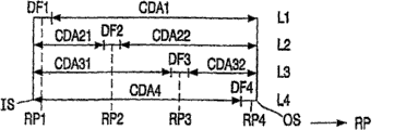
Fig. 2 represent DMA have position on four layers the disc according to embodiments of the invention.Described layer L1 to L4 lines up stack with vertical direction.Described radial position RP is described along transverse axis.The inboard IS of described disc D is side embracing layer L1 to L4 leftward, and the outside OS of described disc is at right-hand side embracing layer L1 to L4.There is a defect management DF1 in radial position RP1 at the layer L1 of the inboard IS of described disc D, can obtain may be on one deck maximal contiguous data area CDA1.There is defect management DF4 in the radial position RP4 of the layer L4 of OS outside described disc D, and can obtain may be at the maximal contiguous data area CDA4 on the layer L4.There is defect management DF2 in radial position RP2 at layer L2, and has defect management DF3 at the radial position RP3 of layer L3.Described layer L2 has two big relatively data area CDA21 and CDA22, and described layer L3 has two big relatively data area CDA31 and CDA32.Described defect management DF1 to DF4 has the radial position RP1 to RP4 that is evenly distributed on the disc D.
The distribution of described defect area DF1 to DF4, promptly every layer only exists a defect area, and maximal contiguous data area CDAi may be provided.On the other hand, because the different radial position RP1 to RP4 of described defect management DF1 to DF4, the actual radial position on disc D and might be minimum near the distance between the defect management.
Described distribution can easily be applicable to greater or less than four layers.Describedly be used for two-layer distribution as shown in Figure 3.
Thereby location defect management DFi obtains the even distribution of defect management Dfi on disc D on described layer L2 and L3, and this is unimportant.As long as the defect management DFi on layer L2 and L3 has different radial positions with respect to other layers L1 with defect management DFi on the L4, the distance from actual radial position to one of defect management DFi will be littler.Described defect management DF2 and DF3 can be positioned at same radial position.Only importantly, at least two defect areas have different radial positions and do not appear at same radial position, thereby make that to jump to the distance of immediate management area Dfi from the zone errors of one of described data area CDAi littler.
Fig. 3 represent DMA have position on the two-layer disc according to embodiments of the invention.
Described defect management DF1 is positioned at the radial position RP1 of the layer L1 of the inboard IS of disc D.Described defect management DF2 is positioned at the radial position RP2 of the layer L2 of disc D outside OS.Described maximum possible contiguous data area is all effective on layer L1 and L2.And in zone errors and described the most minimum near the distance between defect management DF1, the DF2.
Fig. 4 represent DMA have position on the two-layer disc according to embodiments of the invention.
Described defect management DF1 is positioned at the radial position RP1 of the layer L1 of the inboard IS of disc D.Described defect management DF3 is positioned at the radial position RP3 of the layer L3 of disc D outside OS.Described defect management DF2 is positioned at the radial position RP2 of the centre of the radial position RP1 of layer L2 and RP3.Described maximum possible contiguous data area is effective on layer L2.Two big contiguous data area are all effective on described layer L1.Zone errors and described be as shown in Figure 3 half of embodiment near the distance between defect management DF1, DF2 or the DF3.
Fig. 5 represent DMA have position on the two-layer disc according to embodiments of the invention.
Described defect management DF1 is positioned at the radial position RP1 of the layer L1 of the inboard IS of disc D.Described defect management DF4 is positioned at the radial position RP4 of the layer L2 of disc D outside OS.Described defect management DF2 is positioned at the radial position RP2 of layer L1, and described defect management DF3 is positioned at the radial position RP3 of layer L2.The radial position RP1 to RP4 that equates to select described defect management DF1 to DF4 according to the radial distance between the DF1 to DF4 of continuous defect management area.Two big contiguous data area are all effective at layer L1 and L2.Zone errors and near the distance of defect management DF1 to DF4 less than as shown in Figure 3 embodiment.
It should be noted that the foregoing description is explained rather than restriction the present invention, and those of ordinary skills can design many optional embodiments in the scope that does not break away from claims.For example, with respect to certain radial position of certain one deck, the position of DMA can be stored in the fixed position of disc, for example in head zone.In described embodiment, commutative with respect to the position of the DMA of the inboard IS of disc and outside OS.
In the claims, the reference marker in any bracket should not be construed as the restriction to claim.Word " comprises " not getting rid of and also comprises element and the step of claim outside listed.The present invention can utilize the device of the hardware that comprises several individual components and the device of corresponding programmed computer to realize.In having enumerated the equipment claim of several means, these devices several are presented as the hardware of one and identical entry.At least, the certain measures of mentioning at different dependent claims is not meant that the combination of these measures does not have advantage.
Claims (11)
1. the method for a location defect management on a CD, this CD comprises that at least two can be write layer, described method is included in described at least two Different Diameter of different layers that can write layer at least two defect managements of location positioning.
2. according to the method for the described location of claim 1, wherein this location is not positioned other defect management first radial position of described at least two defect managements.
3. according to the method for the described location of claim 1, wherein this location evenly is positioned at described two defect managements the radial position of described disc at least.
4. according to the method for claim 1 or 2 described location, wherein this location is defect management in location at least two each layers that can write layer.
5. according to the method for the described location of claim 1, first radial position in the wherein said different radial positions is the inboard of described disc, and second radial position in the described different radial position is the outside of described disc.
6. according to the method for the described location of claim 1, wherein
Can write layer for these at least two and comprise that first can write layer and second can write layer,
These at least two defect managements comprise first defect management, second defect management and the 3rd defect management,
This location:
This first defect management is positioned at that this first can write that layer is gone up, is first radial position place of described disc inboard in the described different radial positions,
With the 3rd defect management be positioned at that this first can write that layer is gone up, in the described different radial positions corresponding to the 3rd radial position in this disc outside, and
This second defect management is positioned at this second second radial position that can write on the layer, in the described different radial positions, and this second radial position is between described first radial position and described the 3rd radial position.
7. according to the method for the described location of claim 1, wherein can write layer and comprise that first can write layer and second can write layer for these at least two, and this location makes first group of a plurality of defect management of these at least two defect managements be positioned at first can to write layer last a plurality of first a different radial position, and the second group of a plurality of defect management that makes these at least two defect managements are positioned at second and can write layer last a plurality of second a different radial position, thus the selected radial distance that equates between the continuous diametrically defect management of obtaining of described first and second radial positions.
8. according to the method for the described location of claim 1, also comprise:
Come rotary CD by motor,
By focus circuit focus signal is offered optical element and can write on the layer with at least two of can write in the layer that light beam focused on this CD,
Provide a positioning signal to come this light beam of radial location by positioning circuit with relative CD,
Write data to CD or fetch data by signal processing circuit from optical disk reading,
Control by controller: the rotation of CD, providing of focus signal, providing of positioning signal, and control writes data to CD and fetches data from optical disk reading, perhaps write data to the data area or from the data area reading of data, perhaps write data to one of defect management or from one of defect management reading of data, wherein positioning circuit be controlled to the zone errors of light beam from one of data area move in the defect management near defect management.
9. according to the method for the described location of claim 8, another layer different that is positioned at CD in this defect management wherein with zone errors near defect management.
10. device that is used to visit CD, described CD comprise at least two at least two defect managements can writing layer and be positioned the different radial positions of described at least two different layers that can write layer, and described device comprises:
A motor that is used to rotate this CD,
One is used for that focus signal is offered optical element and can writes focus circuits on one of layer light beam is focused at least two of CD,
One is used to provide positioning signal to locate the positioning circuit of this light beam with this disc radial direction relatively,
One is used to the signal processing circuit that writes data to CD or fetch data from optical disk reading, and
A controller, be used for control: the rotation of CD, providing of focus signal, providing of positioning signal, and control writes data to CD and fetches data from optical disk reading, perhaps write data to the data area or from the data area reading of data, perhaps write data to one of defect management or from one of defect management reading of data, wherein this controller is arranged to control positioning circuit, with the zone errors of light beam from one of data area are moved in the defect management near defect management.
11. according to the described device of claim 10, another layer different that is positioned at CD in this defect management wherein with zone errors near defect management.
Applications Claiming Priority (3)
| Application Number | Priority Date | Filing Date | Title |
|---|---|---|---|
| EP02078974 | 2002-09-25 | ||
| EP02078974.9 | 2002-09-25 | ||
| PCT/IB2003/003506 WO2004029964A1 (en) | 2002-09-25 | 2003-08-08 | Defect area management |
Publications (2)
| Publication Number | Publication Date |
|---|---|
| CN1685428A CN1685428A (en) | 2005-10-19 |
| CN1685428B true CN1685428B (en) | 2010-10-13 |
Family
ID=32039168
Family Applications (1)
| Application Number | Title | Priority Date | Filing Date |
|---|---|---|---|
| CN03822724XA Expired - Fee Related CN1685428B (en) | 2002-09-25 | 2003-08-08 | Method for positioning defect management area and related device |
Country Status (8)
| Country | Link |
|---|---|
| US (1) | US20090285063A1 (en) |
| EP (1) | EP1547087A1 (en) |
| JP (1) | JP2006500713A (en) |
| KR (1) | KR20050057547A (en) |
| CN (1) | CN1685428B (en) |
| AU (1) | AU2003249537A1 (en) |
| BR (1) | BR0306463A (en) |
| WO (1) | WO2004029964A1 (en) |
Families Citing this family (9)
| Publication number | Priority date | Publication date | Assignee | Title |
|---|---|---|---|---|
| CN100412957C (en) * | 2005-05-30 | 2008-08-20 | 松下电器产业株式会社 | Multi-layer information storage medium and information apparatus |
| JP4605147B2 (en) | 2006-11-30 | 2011-01-05 | Tdk株式会社 | Optical recording method, optical recording apparatus, and multilayer optical recording medium for multilayer optical recording medium |
| JP4605148B2 (en) | 2006-12-15 | 2011-01-05 | Tdk株式会社 | Optical recording method and optical recording apparatus for multilayer optical recording medium |
| WO2009027918A1 (en) * | 2007-08-30 | 2009-03-05 | Koninklijke Philips Electronics N.V. | Near field optical recording device and method of operating a near field optical recording device |
| JP2009230794A (en) * | 2008-03-21 | 2009-10-08 | Sharp Corp | Information processing unit, control method and control program for information processing unit, and recording medium with control program for information processing unit recorded thereon |
| KR101683790B1 (en) | 2009-02-25 | 2016-12-09 | 삼성전자주식회사 | An information storage medium, recording/reproducing apparatus and recording/reproducing method |
| JP5640251B2 (en) * | 2011-01-17 | 2014-12-17 | 株式会社アルメディオ | Optical disc inspection apparatus and optical disc inspection method |
| JP5433661B2 (en) * | 2011-10-14 | 2014-03-05 | 日立コンシューマエレクトロニクス株式会社 | Optical disc apparatus and information recording method |
| CN108112072A (en) * | 2016-11-24 | 2018-06-01 | 光宝电子(广州)有限公司 | Alignment system and its localization method |
Citations (2)
| Publication number | Priority date | Publication date | Assignee | Title |
|---|---|---|---|---|
| EP0426409B1 (en) * | 1989-10-30 | 1997-01-02 | Matsushita Electric Industrial Co., Ltd. | Multilayered optial disk |
| CN1330793A (en) * | 1998-10-22 | 2002-01-09 | 松下电器产业株式会社 | Information recording medium, method and apparatus for managing defect thereof |
Family Cites Families (12)
| Publication number | Priority date | Publication date | Assignee | Title |
|---|---|---|---|---|
| JPH0269264A (en) * | 1988-09-03 | 1990-03-08 | Oki Electric Ind Co Ltd | Driving of gas discharge type optical head and gas discharge type optical head |
| US5729525A (en) * | 1995-06-21 | 1998-03-17 | Matsushita Electric Industrial Co., Ltd. | Two-layer optical disk |
| JPH09259537A (en) * | 1996-03-25 | 1997-10-03 | Toshiba Corp | Information record disk having alternate area |
| JPH09259576A (en) * | 1996-03-25 | 1997-10-03 | Toshiba Corp | Information recording disk with a plurality of control regions |
| EP0818776B1 (en) * | 1996-07-10 | 2008-02-13 | Hitachi, Ltd. | Optical disc apparatus accessing method and system therefor |
| JP3130258B2 (en) * | 1996-10-25 | 2001-01-31 | インターナショナル・ビジネス・マシーンズ・コーポレ−ション | Disk device and data reassignment method |
| JP3875492B2 (en) * | 1998-09-14 | 2007-01-31 | 株式会社東芝 | Information recording medium, information recording apparatus, information recording method, information reproducing apparatus, and information reproducing method |
| KR100366644B1 (en) * | 1998-12-30 | 2003-02-20 | 삼성전자 주식회사 | Disc storing start location information for each zone and data management method using the same information |
| MXPA02004748A (en) * | 1999-11-10 | 2004-01-19 | Thomson Licensing Sa | A method of disaster recovery for re writable disk media. |
| EP1176586B1 (en) * | 2000-07-26 | 2005-09-14 | Kabushiki Kaisha Toshiba | Information recording medium with index header |
| CN101281774A (en) * | 2002-01-22 | 2008-10-08 | 松下电器产业株式会社 | Multi-layer information recording medium, recording apparatus, and recording method |
| US7577073B2 (en) * | 2003-08-08 | 2009-08-18 | Koninklijke Philips Electronics N.V. | Defect area management |
-
2003
- 2003-08-08 AU AU2003249537A patent/AU2003249537A1/en not_active Abandoned
- 2003-08-08 EP EP03798249A patent/EP1547087A1/en not_active Withdrawn
- 2003-08-08 WO PCT/IB2003/003506 patent/WO2004029964A1/en active Application Filing
- 2003-08-08 CN CN03822724XA patent/CN1685428B/en not_active Expired - Fee Related
- 2003-08-08 JP JP2004539269A patent/JP2006500713A/en active Pending
- 2003-08-08 BR BR0306463-8A patent/BR0306463A/en not_active IP Right Cessation
- 2003-08-08 KR KR1020057004917A patent/KR20050057547A/en not_active Application Discontinuation
-
2009
- 2009-07-09 US US12/499,851 patent/US20090285063A1/en not_active Abandoned
Patent Citations (2)
| Publication number | Priority date | Publication date | Assignee | Title |
|---|---|---|---|---|
| EP0426409B1 (en) * | 1989-10-30 | 1997-01-02 | Matsushita Electric Industrial Co., Ltd. | Multilayered optial disk |
| CN1330793A (en) * | 1998-10-22 | 2002-01-09 | 松下电器产业株式会社 | Information recording medium, method and apparatus for managing defect thereof |
Non-Patent Citations (1)
| Title |
|---|
| CN 1330793 A,全文. |
Also Published As
| Publication number | Publication date |
|---|---|
| EP1547087A1 (en) | 2005-06-29 |
| WO2004029964A1 (en) | 2004-04-08 |
| BR0306463A (en) | 2004-10-13 |
| CN1685428A (en) | 2005-10-19 |
| KR20050057547A (en) | 2005-06-16 |
| JP2006500713A (en) | 2006-01-05 |
| US20090285063A1 (en) | 2009-11-19 |
| AU2003249537A1 (en) | 2004-04-19 |
Similar Documents
| Publication | Publication Date | Title |
|---|---|---|
| CN1685428B (en) | Method for positioning defect management area and related device | |
| JP2008527602A5 (en) | ||
| JP2008257837A (en) | Multiple sector reassign on write error for disk drive | |
| CN1659656B (en) | Method and device for writing a multi-layer optical disc | |
| KR20020078661A (en) | A optical disc and recording layer | |
| US6480949B2 (en) | Disk drive block ordering system | |
| US7577073B2 (en) | Defect area management | |
| KR101035098B1 (en) | Recording method and device for recording information on dual layer recordable disks | |
| JP4394898B2 (en) | Storage device and storage medium | |
| KR100464438B1 (en) | Method for heads switching which use mapping of numbers of track | |
| CN101252017B (en) | Optical disc drive and method for processing recorded data | |
| EP2413316B1 (en) | Method and system for processing information from optical disk layers | |
| JP2001155349A (en) | Interlayer movement control method and optical disk device | |
| JP2668684B2 (en) | Sector format method | |
| KR20060069441A (en) | Device and method for recording data blocks | |
| JP2007515740A (en) | Optical disc for storing both data requiring defect management and real-time AV data | |
| KR100392615B1 (en) | Method for controlling head position of hard disk drive having three bursts | |
| JP2601615B2 (en) | Information recording method | |
| JPH06325494A (en) | Defect relieving device for memory device | |
| KR100574991B1 (en) | Method for detecting poor assembling in offline-servo-track-written disk drive | |
| JPH0760573B2 (en) | Write control method for rotary memory device | |
| JP2005108280A (en) | Optical disk device | |
| JP4972709B2 (en) | Information recording medium and information reproducing method | |
| JPH0845194A (en) | Disk and disk device | |
| JP2001265534A (en) | Access control method and disk device using the same |
Legal Events
| Date | Code | Title | Description |
|---|---|---|---|
| C06 | Publication | ||
| PB01 | Publication | ||
| C10 | Entry into substantive examination | ||
| SE01 | Entry into force of request for substantive examination | ||
| C14 | Grant of patent or utility model | ||
| GR01 | Patent grant | ||
| C17 | Cessation of patent right | ||
| CF01 | Termination of patent right due to non-payment of annual fee |
Granted publication date: 20101013 Termination date: 20110808 |