CN1665746A - Tapelike material containing carbon nanotube and production method for carbon nanotube and electric field emission type electrode containing the tapelike material and production method therefor - Google Patents
Tapelike material containing carbon nanotube and production method for carbon nanotube and electric field emission type electrode containing the tapelike material and production method therefor Download PDFInfo
- Publication number
- CN1665746A CN1665746A CN038157977A CN03815797A CN1665746A CN 1665746 A CN1665746 A CN 1665746A CN 038157977 A CN038157977 A CN 038157977A CN 03815797 A CN03815797 A CN 03815797A CN 1665746 A CN1665746 A CN 1665746A
- Authority
- CN
- China
- Prior art keywords
- carbon nanotube
- electrode
- cathode
- arc
- electric arc
- Prior art date
- Legal status (The legal status is an assumption and is not a legal conclusion. Google has not performed a legal analysis and makes no representation as to the accuracy of the status listed.)
- Pending
Links
Images


Classifications
-
- C—CHEMISTRY; METALLURGY
- C01—INORGANIC CHEMISTRY
- C01B—NON-METALLIC ELEMENTS; COMPOUNDS THEREOF; METALLOIDS OR COMPOUNDS THEREOF NOT COVERED BY SUBCLASS C01C
- C01B32/00—Carbon; Compounds thereof
- C01B32/15—Nano-sized carbon materials
- C01B32/158—Carbon nanotubes
- C01B32/16—Preparation
- C01B32/162—Preparation characterised by catalysts
-
- B—PERFORMING OPERATIONS; TRANSPORTING
- B82—NANOTECHNOLOGY
- B82Y—SPECIFIC USES OR APPLICATIONS OF NANOSTRUCTURES; MEASUREMENT OR ANALYSIS OF NANOSTRUCTURES; MANUFACTURE OR TREATMENT OF NANOSTRUCTURES
- B82Y30/00—Nanotechnology for materials or surface science, e.g. nanocomposites
-
- B—PERFORMING OPERATIONS; TRANSPORTING
- B82—NANOTECHNOLOGY
- B82Y—SPECIFIC USES OR APPLICATIONS OF NANOSTRUCTURES; MEASUREMENT OR ANALYSIS OF NANOSTRUCTURES; MANUFACTURE OR TREATMENT OF NANOSTRUCTURES
- B82Y10/00—Nanotechnology for information processing, storage or transmission, e.g. quantum computing or single electron logic
-
- B—PERFORMING OPERATIONS; TRANSPORTING
- B82—NANOTECHNOLOGY
- B82Y—SPECIFIC USES OR APPLICATIONS OF NANOSTRUCTURES; MEASUREMENT OR ANALYSIS OF NANOSTRUCTURES; MANUFACTURE OR TREATMENT OF NANOSTRUCTURES
- B82Y40/00—Manufacture or treatment of nanostructures
-
- H—ELECTRICITY
- H01—ELECTRIC ELEMENTS
- H01J—ELECTRIC DISCHARGE TUBES OR DISCHARGE LAMPS
- H01J1/00—Details of electrodes, of magnetic control means, of screens, or of the mounting or spacing thereof, common to two or more basic types of discharge tubes or lamps
- H01J1/02—Main electrodes
- H01J1/30—Cold cathodes, e.g. field-emissive cathode
- H01J1/304—Field-emissive cathodes
-
- H—ELECTRICITY
- H01—ELECTRIC ELEMENTS
- H01J—ELECTRIC DISCHARGE TUBES OR DISCHARGE LAMPS
- H01J9/00—Apparatus or processes specially adapted for the manufacture, installation, removal, maintenance of electric discharge tubes, discharge lamps, or parts thereof; Recovery of material from discharge tubes or lamps
- H01J9/02—Manufacture of electrodes or electrode systems
- H01J9/022—Manufacture of electrodes or electrode systems of cold cathodes
- H01J9/025—Manufacture of electrodes or electrode systems of cold cathodes of field emission cathodes
-
- C—CHEMISTRY; METALLURGY
- C01—INORGANIC CHEMISTRY
- C01B—NON-METALLIC ELEMENTS; COMPOUNDS THEREOF; METALLOIDS OR COMPOUNDS THEREOF NOT COVERED BY SUBCLASS C01C
- C01B2202/00—Structure or properties of carbon nanotubes
- C01B2202/20—Nanotubes characterized by their properties
- C01B2202/30—Purity
-
- C—CHEMISTRY; METALLURGY
- C01—INORGANIC CHEMISTRY
- C01B—NON-METALLIC ELEMENTS; COMPOUNDS THEREOF; METALLOIDS OR COMPOUNDS THEREOF NOT COVERED BY SUBCLASS C01C
- C01B2202/00—Structure or properties of carbon nanotubes
- C01B2202/20—Nanotubes characterized by their properties
- C01B2202/34—Length
-
- C—CHEMISTRY; METALLURGY
- C01—INORGANIC CHEMISTRY
- C01B—NON-METALLIC ELEMENTS; COMPOUNDS THEREOF; METALLOIDS OR COMPOUNDS THEREOF NOT COVERED BY SUBCLASS C01C
- C01B2202/00—Structure or properties of carbon nanotubes
- C01B2202/20—Nanotubes characterized by their properties
- C01B2202/36—Diameter
-
- H—ELECTRICITY
- H01—ELECTRIC ELEMENTS
- H01J—ELECTRIC DISCHARGE TUBES OR DISCHARGE LAMPS
- H01J2201/00—Electrodes common to discharge tubes
- H01J2201/30—Cold cathodes
- H01J2201/304—Field emission cathodes
- H01J2201/30446—Field emission cathodes characterised by the emitter material
- H01J2201/30453—Carbon types
- H01J2201/30469—Carbon nanotubes (CNTs)
-
- Y—GENERAL TAGGING OF NEW TECHNOLOGICAL DEVELOPMENTS; GENERAL TAGGING OF CROSS-SECTIONAL TECHNOLOGIES SPANNING OVER SEVERAL SECTIONS OF THE IPC; TECHNICAL SUBJECTS COVERED BY FORMER USPC CROSS-REFERENCE ART COLLECTIONS [XRACs] AND DIGESTS
- Y10—TECHNICAL SUBJECTS COVERED BY FORMER USPC
- Y10S—TECHNICAL SUBJECTS COVERED BY FORMER USPC CROSS-REFERENCE ART COLLECTIONS [XRACs] AND DIGESTS
- Y10S977/00—Nanotechnology
- Y10S977/84—Manufacture, treatment, or detection of nanostructure
- Y10S977/842—Manufacture, treatment, or detection of nanostructure for carbon nanotubes or fullerenes
- Y10S977/843—Gas phase catalytic growth, i.e. chemical vapor deposition
-
- Y—GENERAL TAGGING OF NEW TECHNOLOGICAL DEVELOPMENTS; GENERAL TAGGING OF CROSS-SECTIONAL TECHNOLOGIES SPANNING OVER SEVERAL SECTIONS OF THE IPC; TECHNICAL SUBJECTS COVERED BY FORMER USPC CROSS-REFERENCE ART COLLECTIONS [XRACs] AND DIGESTS
- Y10—TECHNICAL SUBJECTS COVERED BY FORMER USPC
- Y10S—TECHNICAL SUBJECTS COVERED BY FORMER USPC CROSS-REFERENCE ART COLLECTIONS [XRACs] AND DIGESTS
- Y10S977/00—Nanotechnology
- Y10S977/84—Manufacture, treatment, or detection of nanostructure
- Y10S977/842—Manufacture, treatment, or detection of nanostructure for carbon nanotubes or fullerenes
- Y10S977/844—Growth by vaporization or dissociation of carbon source using a high-energy heat source, e.g. electric arc, laser, plasma, e-beam
-
- Y—GENERAL TAGGING OF NEW TECHNOLOGICAL DEVELOPMENTS; GENERAL TAGGING OF CROSS-SECTIONAL TECHNOLOGIES SPANNING OVER SEVERAL SECTIONS OF THE IPC; TECHNICAL SUBJECTS COVERED BY FORMER USPC CROSS-REFERENCE ART COLLECTIONS [XRACs] AND DIGESTS
- Y10—TECHNICAL SUBJECTS COVERED BY FORMER USPC
- Y10T—TECHNICAL SUBJECTS COVERED BY FORMER US CLASSIFICATION
- Y10T29/00—Metal working
- Y10T29/49—Method of mechanical manufacture
- Y10T29/49002—Electrical device making
- Y10T29/49117—Conductor or circuit manufacturing
- Y10T29/49124—On flat or curved insulated base, e.g., printed circuit, etc.
Landscapes
- Engineering & Computer Science (AREA)
- Chemical & Material Sciences (AREA)
- Nanotechnology (AREA)
- Materials Engineering (AREA)
- Physics & Mathematics (AREA)
- Crystallography & Structural Chemistry (AREA)
- Condensed Matter Physics & Semiconductors (AREA)
- Organic Chemistry (AREA)
- Manufacturing & Machinery (AREA)
- General Physics & Mathematics (AREA)
- Mathematical Physics (AREA)
- Theoretical Computer Science (AREA)
- Inorganic Chemistry (AREA)
- Chemical Kinetics & Catalysis (AREA)
- Composite Materials (AREA)
- Carbon And Carbon Compounds (AREA)
Abstract
A uniform, high-density tapelike material containing a high-purity, multi-layer or single-layer carbon nanotube, and a production method for a high-purity, multi-layer or single-layer carbon nanotube, and a high-performance electric field emission type electrode containing that tapelike material and a production method for this electric field emission type electrode. When a carbon nanotube is synthesized by arc-discharging, a hollow electrode (11) is used as an anode electrode to generate arc between the hollow electrode and a cathode electrode (2) consisting of a carbon material, while an inert gas or a mixture gas containing an inert gas is being sprayed from the interior (11a) of the hollow electrode toward the cathode electrode to form an arc discharge path along the gas flow, whereby a high-purity carbon nanotube can be produced with the irregular movement of a cathode spot prevented. In addition, when the relative position of the both electrodes is moved to move the cathode spot of the arc (3) on a cathode material, a tapelike carbon nanotube is sysnthesized.
Description
Technical field
The present invention relates to contain the manufacture method of banded material, multilayer or the individual layer high-purity carbon nano tube of multilayer or individual layer high-purity carbon nano tube.Also relate to field emission electrode and the manufacture method thereof of using the banded material that contains multilayer or individual layer high-purity carbon nano tube.
Background technology
Carbon nanotube (CNT) obtains by carry out arc-over between two kinds of carbon materials, carbon atom is arranged in sexangle regularly, form graphite linings, this graphite linings bends to round shape, promptly form carbon nanotube (CNT), the round shape that graphite linings forms is an individual layer, then is single-layer carbon nano-tube (SWCNT), and its diameter is about 1-and counts nm.The tubular of graphite linings is that multilayer is overlapping for concentric circles, then is multilayer carbon nanotube (MWCNT), and its diameter is about the tens of nm of several nm-.Single-layer carbon nano-tube synthetic was to use the carbon dioxide process carbon electrode that contains metal catalyst or catalyst metal imbedded anode electrode in the past, synthesized by arc-over.Carbon material described here is meant with carbon to be conductive materials (following identical) such as the amorphous of main component or graphite matter.
Generally speaking, about between two kinds of carbon materials, carrying out the technology that arc-over comes synthesizing carbon nanotubes (CNT), various motions have been proposed at present.For example the someone proposes: in encloses container, be full of helium or argon, make pressure in the encloses container be 200Torr or more than, by carrying out the technology (for example Japanese kokai publication hei 6-280116 communique) that the carbon direct current arc is discharged and made carbon nanotube.
The somebody proposes: be full of helium in encloses container, in the heating encloses container, making its internal temperature is 1000-4000 ℃, control this temperature simultaneously on one side, on one side carry out the direct current arc discharge between the discharge electrode of carbon-point containing, thus the technology (for example Japanese kokai publication hei 6-157016 communique) of the factory length carbon nanotube consistent with diameter branch.
The somebody proposes: with (a) the negative electrode stores is reclaimed by the gradation formula and change the continous way recovery into, (b) avoid the arc instability that produces along with the growth of negative electrode stores, (c) prevent to be exposed to the low problem of yield that causes under the electric arc for a long time because of the negative electrode stores, (d) in the extensive region of cathode surface, generate carbon nanotube, be purpose, in the encloses container that has been full of rare gas element, between the electrode of opposite of along continuous straight runs setting, carry out arc-over, make simultaneously electrode relative to and continuously or off and on rotation or come and go move, make the technology (for example Japanese kokai publication hei 7-216660 communique) of carbon nanotube thus.
Also the someone proposes: make arc-over in containing one or more atmosphere that are selected from air, oxygen, nitrogen, make on one side discoid negative electrode continuously or rotation indirectly, at negative electrode form the technology (for example Japanese kokai publication hei 2002-88592 communique) of graphite fibre on one side.
The someone proposes again: will be arranged at the carbon dioxide process carbon electrode anode established in the encloses container, relatively and negative electrode around use heater heats, between two electrodes, carry out direct current arc discharge then, increase the purity of carbon nanotube of generation and the technology (for example Japanese kokai publication hei 2000-203820 communique) of receipts amount with this.
The someone proposes again: by heating unit will be arranged in the encloses container, the anodic head that contains carbon dioxide process carbon electrode heats, carry out arc-over then, can generate the technology (for example TOHKEMY 2000-344505 communique) of size, the uniform carbon nanotube of quality thus efficiently.
But, in the manufacture method of above-mentioned carbon nanotube, exist following technical problem.
That is, carbon nanotube generates at following position: be piled up in the material on the carbon dioxide process carbon electrode that carries out arc-over negative electrode one side partly, that contain carbon atom; Or in the part of the coal that is attached to electric arc periphery position of dispersing.But according to the manufacture method of the carbon nanotube in the above-mentioned existing example, mixing inevitably except that carbon nanotube in the product has graphite, agraphitic carbon etc., and the ratio of carbon nanotube itself is low.
In the common arc-over, its cathode spot can optionally produce at high position in evaporation of electron.If but cathode spot produces continually, then the evaporation of electron at this position can weaken, and cathode spot can move to other position that evaporation of electron can be higher.Therefore, in the common arc-over, cathode spot is irregular intensely to be moved, and carries out arc-over simultaneously.And cathode spot departs from the position relative with anode greatly and surpasses sometimes, surpasses the load voltage capacity of power supply, might make the electric arc extinguishing arc.Like this, in the violent irregular mobile arc-over of cathode spot, if we observe negative electrode certain a bit, chemical factors such as its temperature and carbon vapour density have very big change in time.Therefore, it may be the condition that has reached easy synthesizing carbon nanotubes in during a certain, but in during another may be the condition that is difficult to synthesizing carbon nanotubes, or the easy condition of decomposing of carbon nanotube, the result has synthesized the carbon nanotube that contains more impurity in the position that whole cathode spot produces.Here, decomposition about carbon nanotube is meant following phenomenon: because the formation mechanism of carbon nanotube itself still has a lot of indeterminate parts, can't conclude whether decomposition is arranged, if but in a certain temperature range, carbon exists more stable than carbon nanotube structure with the form of graphite or agraphitic carbon, the structure that then produces carbon nanotube changes the phenomenon of graphite or agraphitic carbon structure into; Perhaps under quite high temperature, constitute one group of the carbon nanotube that generated (bunch) carbon atom (bunch) and obtain discharging, produce the phenomenon of carbon nanotube disintegration.Itself also at high temperature carries out the generative process of carbon nanotube, therefore the phenomenon of above-mentioned bunch release may also can take place in this generative process, but also can be speculated as under the optimum temps that carbon nanotube generates, therefore the formation speed of carbon nanotube has synthesized carbon nanotube greater than disintegration rate (bunch release rate).
Therefore, in the past for the synthetic ratio of the stable and carbon nanotube that improves electric arc, taked aforesaid arc discharge device to be located in the encloses container, suitably selected the temperature around the electrode in atmosphere gas kind in the encloses container and the encloses container, and the means of controlling.
But, just regulate kind and the temperature of pressure or encloses container or the temperature around the interior electrode of encloses container of the atmosphere gas in the encloses container, be difficult to make the cathode spot of electric arc to be completely fixed, still can only reclaim as the negative electrode stores or the coaly material of more impurity and carbon nanotube mixture.Therefore the result is the yield reduction of carbon nanotube, simultaneously in order to improve the purity of carbon nanotube, must carry out complicated purification operations, the reason that this production cost that becomes carbon nanotube increases.And, equipment enlarging, cost of equipment is huge, is difficult to simultaneously by a large amount of synthesizing carbon nanotubes of arc-over.
As mentioned above, for continuously, high yield or as above make carbon nanotube to high-density, the someone has proposed to carry out the method that relatively moves of electrode, but the main purpose of existing this technology is just in order to reclaim the still more negative electrode stores of impurity continuously.By speed of relative movement is speeded, also may obtain highdensity carbon nanotube, but its thickness has only about 100 μ m, even use the stripper etc. of cutter shape, also be not easy to reclaim.And in existing moving method, owing to move repeatedly in same place, the temperature of negative electrode slowly rises, and the temperature experience that electric arc produces point changes.Therefore, can not be stably, high purity, make carbon nanotube with high yield.
In addition, because the pencil and the high crystalline of carbon nanotube, people consider it as ejected electron source, field, be used for the cathode material of fluorescent display tube or Field Emission Display (FED) etc. and the probe of electron microscope etc., but existing carbon nanotube can only obtain containing the Powdered or block of more impurity, the purifying technique complexity, operation and processing are all very numerous and diverse.
In addition, carbon nanotube has following character: compression or immerse liquid after make its drying again, then assemble by Van der Waals force between mutually, pulverizing in operation, the acid solution treatment process etc. of purification process, carbon nanotube is gathered into bulk, thick pencil, and the pencil of carbon nanotube is lost to the greatest extent.Like this, when carbon nanotube becomes bulk or thick pencil, during its pencil forfeiture, as the performance in ejected electron source, field remarkable variation just.
In addition, common by arc-over synthetic carbon nanotube than good crystallinity, quality height by thermal decomposition method synthetic carbon nanotube, but Arc Temperature height, can not on substrates such as silicon, directly synthesize membranaceous carbon nanotube with this arc process, need to adopt thermal decomposition method, or very thin the spreading out of powder formed carbon nanotube that will make by arc process, be pasted on the substrate with certain methods again.But thermal decomposition method can not obtain high-quality carbon nanotube, when using the powder formed carbon nanotube that arc discharge method in the past makes, the problem pockety of the carbon nanotube on the substrate can occur.
And, for Powdered or block carbon nanotube for example are pasted on substrate or the electrode equably as ejected electron source, field, adopted following method: carbon nanotube is scattered in conductive paste (for example silver-colored paste etc.), coat on substrate or the electrode with this state, carry out drying, sintering, afterwards, in order to make the carbon nanotube exposing surface, adopt the method for milled processed or laser or Cement Composite Treated by Plasma, but be difficult to obtain stable quality like this as field emitting electronic source, complex process in addition, production cost increases.
Summary of the invention
Purpose of the present invention is as follows: the even and highdensity banded material that obtains to contain multilayer or individual layer high-purity carbon nano tube; Encloses container need not be used, under air atmosphere, multilayer or individual layer high-purity carbon nano tube can be easily generated by arc-over; Use above-mentioned banded material, obtain the high performance field emission electrode that brings by high-purity carbon nano tube; And can easily make this field emission electrode.
(1) the banded material that contains carbon nanotube of the present invention generates by arc discharge method.
(2) the banded material thickness that contains carbon nanotube of the present invention is that 10-500 μ m, width are 1-10mm and have random length, mainly has the flocculence aggregate of carbon nanotube.
(3) the banded material that contains carbon nanotube of the present invention is to form the arc-over path along the air-flow of being supplied with to the cathode electrode that contains carbon material by anode electrode, by moving the relative position of two electrodes, the cathode spot of electric arc is moved and synthetic on cathode material simultaneously.
(4) the banded material that contains carbon nanotube of the present invention is to produce electric arc along the air-flow of being supplied with to the cathode electrode that contains carbon material by the anode electrode inside of hollow, by moving the relative position of two electrodes, the cathode spot of electric arc is moved and synthetic on cathode material simultaneously.
(5) the banded material that contains carbon nanotube of the present invention be along by the anode electrode inside of hollow to the cathode electrode that contains carbon material, produce electric arc with the air-flow of supplying with as the metal-powder or the metallic compound of catalyzer, by moving the relative position of two electrodes, the cathode spot of electric arc is moved and synthetic on cathode material simultaneously.
(6) the following generation of banded material that contains carbon nanotube of the present invention: in above-mentioned (1)-(5), arc-over carries out under air atmosphere.
(7) the following generation of banded material that contains carbon nanotube of the present invention: in above-mentioned (3)-(6), the mixed gas conduct of using argon gas or argon gas and hydrogen by anode to the cathode electrode gas supplied.
(8) the banded material that contains carbon nanotube of the present invention is following synthetic: in above-mentioned (1)-(7), two electrodes are moved, make except electric arc produce and end position near, the electric arc on the cathode surface produces point and experiences through a roughly the same temperature.
(9) the banded material that contains carbon nanotube of the present invention is following synthetic: in above-mentioned (1)-(8), move and make cathode spot can not be positioned at the zone that had once formed cathode spot on the cathode surface once more.
(10) the banded material that contains carbon nanotube of the present invention is following synthetic: in above-mentioned (1)-(9), the place ahead part of in the cathode spot of whole cathode electrode or electric arc or electric arc track cathode electrode on electric arc heated on one side carry out arc-over on one side.
(11) the banded material that contains carbon nanotube of the present invention is following synthetic: in above-mentioned (1)-(10), use resistivity 4000 μ Ω cm or above or thermal conductivity as 40W/mK or following carbon material as cathode electrode.
(12) the banded material that contains carbon nanotube of the present invention is following synthetic: in above-mentioned (1)-(11), using surface profile arithmetic average deviation (Ra) is that 3.2 μ m or following carbon material are as cathode electrode.
(13) following the synthesizing of banded material of containing carbon nanotube of the present invention: in above-mentioned (1)-(12), in the process of cooling of carrying out immediately behind arc-over, the product that generates on the cathode spot track of electric arc sprays into gas.
The carbon nanotube that generates by common arc-over be reclaim on the negative electrode material with piece or the bedded substance piled up as the polycrystalline graphite or the agraphitic carbon of impurity or disperse in around coal.The recovery of these products is difficult for, and reclaims with more impurity, multiple working procedures such as therefore, purification operations afterwards needs to pulverize, centrifugal, acid treatment, filtration or oxidizing fire processing.In addition, the carbon nanotube of purification is Powdered, and therefore the processing after and processing are also complicated.
In the invention of above-mentioned (1)-(13), banded material mainly contains the flocculence aggregate of highly purified carbon nanotube, keeps zonal form, therefore reclaims easily, can obtain the high carbon nanotube of purity with the form that reclaims.In addition, owing to keep belt shape, processing, post-treatment all become very easy.For example, when using, the banded material of a part is pasted on cathode end as the cold-cathode electron source of fluorescent display tube, afterwards if the processing of removing surperficial polycrystalline graphite, agraphitic carbon as required can simplify working process significantly.
(14) field emission electrode of the present invention is made investing on the substrate or be pasted on the substrate as each described banded material folder that contains carbon nanotube in above-mentioned (1)-(13).
(15) field emission electrode of the present invention be with as above-mentioned (1)-(13) in each described banded material that contains carbon nanotube be sandwiched between the substrate or substrate and than between the high material of this substrate deformation performance, the pressurization post-tensioning from, the above-mentioned banded material of peeling off is attached on the aforesaid substrate makes.
(16) field emission electrode of the present invention be with as above-mentioned (1)-(13) in each described banded material clamping that contains carbon nanotube, the face towards anode one side when making it synthetic contacts with aforesaid substrate.
(17) feature of the manufacture method of field emission electrode of the present invention is: will invest on the substrate as each described banded material folder that contains carbon nanotube in above-mentioned (1)-(13), or be pasted on the substrate with conductive adhesive.
(18) feature of the manufacture method of field emission electrode of the present invention is: will be sandwiched between the substrate or substrate and than between the high material of this substrate deformation performance as each described banded material that contains carbon nanotube in above-mentioned (1)-(13), the pressurization post-tensioning from, the above-mentioned banded material of peeling off is attached on the aforesaid substrate.
(19) feature of the manufacture method of field emission electrode of the present invention is: each described banded material that contains carbon nanotube in clamping such as above-mentioned (1)-(13), the face towards anode one side when making it synthetic contacts with aforesaid substrate.
In the invention of above-mentioned (14), (17), contain the carbon nano pipe purity height in the banded material of carbon nanotube, and the state after synthetic, be that every carbon nanotube has only part to join, keep the state of pencil promptly to present uniform film like, therefore can directly be pasted on substrate or the electrode, as high performance field emission electrode.
In the invention of above-mentioned (15), (18), after the pressurization, substrate and the material higher than this substrate deformation performance are pulled away from, carbon nanotube entangled to each other is attached on substrate and the above-mentioned distortion material, the banded material that contains this carbon nanotube, its carbon nano-tube fibre self aggregation position is disassembled (peeling off), is cut off, and cut carbon nano-tube fibre is with to be pulled away from direction parallel-oriented.That is to say that the carbon nano-tube fibre that constitutes banded material is because basically along the growth of the thickness direction of banded material, and its length sufficiently long and intricately are entangled to each other, the release surface after therefore being pulled away from is the burr form.Therefore, can produce the field emission electrode of the electron emission characteristic excellence on the release surface simply.In addition, the surface of above-mentioned distortion material is out of shape because of pressurization, and therefore above-mentioned distortion material forms the shape of substrate surface.That is to say, by the distortion of above-mentioned distortion material, can obtain applied pressure in the whole surperficial stepless action of substrate, do not adhere to the attachment surface of inequality, more uniform carbon nanotube.On the attachment surface of substrate and banded release material, obtained uniform adhesion strength thus.
In the invention of above-mentioned (16), (19), when synthesizing banded material by arc-over, the face of banded material that is positioned at anode one side is stronger than the face of negative electrode one side with the sticking power of substrate, and the above-mentioned distortion material that deformation performance is big is bigger than substrate with the sticking power of carbon nanotube in addition.Therefore, be disposed at substrate one side by the face that banded material is positioned at anode one side, the face that will be positioned at negative electrode one side is disposed at above-mentioned distortion material one side, then can make the adhesion strength of each face roughly the same, therefore can peel off banded material at the mid-depth position of banded material.Can obtain not adhere to the attachment surface of inequality, more uniform carbon nanotube with substrate.
(20) feature of the manufacture method of carbon nanotube of the present invention is: form the arc-over path along the air-flow of being supplied with to the cathode electrode that contains carbon material by anode electrode.
(21) feature of the manufacture method of carbon nanotube of the present invention is: during by the arc-over synthesizing carbon nanotubes, anode electrode uses hollow electrode, spray into rare gas element or contain the mixed gas of rare gas element to the cathode electrode that contains carbon material by the inside of hollow electrode, electric arc is produced.
In the invention of above-mentioned (20), (21), spray into rare gas element such as argon gas for example or contain the mixed gas of rare gas element to cathode electrode by anode electrode, simultaneously therebetween carry out arc-over, then the ionisation of gas degree increases, and has formed the condition that is easy to generate electric arc on gas ejection path.Also can think in addition and form stable anode spot with the contacted anode electrode of the gas surface of containing rare gas element.Therefore, electric arc produces the path and suffers restraints, and prevents that the cathode spot of electric arc from carrying out irregular moving on cathode electrode.The result can make highly purified multilayer carbon nanotube synthetic product in the generation position (centre of electric arc) of this cathode spot that is fixed at the preferential synthesizing carbon nanotubes in the generation position (centre of electric arc) of this cathode spot that is fixed.
(22) feature of the manufacture method of carbon nanotube of the present invention is: along by anode electrode to the cathode electrode that contains carbon material, form the arc-over path with the air-flow of supplying with as the metal-powder or the metallic compound of catalyzer.
(23) feature of the manufacture method of carbon nanotube of the present invention is: during by the arc-over synthesizing carbon nanotubes, anode electrode uses hollow electrode, to the cathode electrode that contains carbon material, with spraying into rare gas element as the metal-powder of catalyzer or metal compound powders or containing the mixed gas of rare gas element, electric arc is produced by the inside of hollow electrode.
In the invention of above-mentioned (22), (23), with spraying into rare gas elementes such as argon gas to cathode electrode by anode electrode as the metal-powder of catalyzer or metal compound powders or containing the mixed gas of rare gas element, then the ionisation of gas degree increases, and has formed the condition that is easy to generate electric arc on gas ejection path.In addition with rare gas element or contain the contacted anode electrode surface-stable of the mixed gas of rare gas element and form anode spot.Therefore, electric arc produces the path and suffers restraints, and can prevent that the irregular of cathode spot of the electric arc on the cathode electrode from moving.Can be at the preferential synthesizing carbon nanotubes in the generation position (centre of electric arc) of this cathode spot that is fixed.In this stage; in the invention of above-mentioned (20), (21); only carry out the arc-over of electrode, therefore can only the synthesizing multilayer carbon nanotube, relative therewith; (22), in the invention of (23); with rare gas element that sprays into to cathode electrode by anode electrode or the mixed gas that contains rare gas element, also spray into metal-powder or metal compound powders as catalyzer, catalyzer is able to the ultra micro granulation through arc heat; as nuclear, single-layer carbon nano-tube is grown thus with it.That is to say, can import catalyst metal effectively, can make highly purified single-layer carbon nano-tube synthetic product in the centre of electric arc or the peripheral position of electric arc in the generation position (centre of electric arc) of the cathode spot that has been fixed.Preferably as the particle of the metal-powder of catalyzer micronize as far as possible.
(24) feature of the manufacture method of carbon nanotube of the present invention is: in above-mentioned (20)-(23), carry out arc-over under air atmosphere.
In the invention of above-mentioned (24),, need make the space between the electrode carry out ionization in order to cause arc-over.The ionization of atom has various processes, in arc-over, conclusively is and the caused ionization process of the bump of electronics.Usually, except that the little He of ordination number, Ne, rare gas element such as Ar, Kr, Xe and electron impact and the ionization efficiency height that produces provides the space that is easy to generate electric arc.Rare gas elementes such as Ar, Kr, Xe are than the ionization efficiency height of oxygen, nitrogen etc., therefore, as described herein, under air atmosphere, on one side the mixed gas of being supplied with these rare gas elementes or containing rare gas element to cathode electrode by anode electrode carries out arc-over on one side, then can concentrate along air flow path to produce electric arc.That is to say, use as plasma gas, electric arc is concentrated, make cathode spot stable by the rare gas element that will supply with to cathode electrode by anode electrode or the mixed gas that contains rare gas element.
In addition, under air atmosphere, oxygen can be brought into the arc-over position, oxidation, the burning of carbon take place.At this moment, though the carbon nanotube that generates also has part oxidized, impurity preferential oxidation, burnings such as agraphitic carbon that temperature of combustion is lower or polycrystalline graphite powder, the result has the effect that improves the carbon nano pipe purity in the product.
(25) feature of the manufacture method of carbon nanotube of the present invention is: in above-mentioned (21), (23), (24), the flow of rare gas element that is sprayed into to cathode electrode by the inside of hollow electrode or the mixed gas that contains rare gas element is: 1mm
2The hole sectional area of hollow electrode is 10-400ml/ minute.
In the invention of above-mentioned (25),, then can not give full play to function as plasma gas if the flow of rare gas element of being supplied with by the hole of hollow electrode or the mixed gas that contains rare gas element is very few; If flow is excessive, what for also can increase as for the concentration of the plasma gas at electrode perimeter position, central part not only, peripheral position also forms the condition that is easy to generate arc-over, and electric arc is concentrated.Therefore, as described herein, be 1mm by making rare gas element of supplying with by the hole of hollow electrode or the flow that contains the mixed gas of rare gas element
2The hole sectional area of hollow electrode is 10-400ml/ minute, can bring into play the function of plasma gas, and can create with peripheral position and compare, and has only the anode electrode central part to carry out the condition of arc-over easily.As a result, cathode spot is concentrated, but yield generate the high carbon nanotube of purity well.
(26) feature of the manufacture method of carbon nanotube of the present invention is: in above-mentioned (20)-(25), the mixed gas that uses argon gas or argon gas and hydrogen is as rare gas element or contain the mixed gas of rare gas element.
In the invention of above-mentioned (26), have the rare gas element such as Ar, Kr, Xe of Ar or above ordination number and electron impact and the ionization efficiency height that produces, the space that is easy to generate electric arc is provided.Ar particularly, be the most cheap, be used for industrial gas easily, therefore can reduce the production cost of carbon nanotube.In addition by in Ar, sneaking into the H of the tens of % of several %-
2As mixed gas, can can't harm the stability of electric arc, increase the receipts amount of carbon nanotube.This may be because H
2Have and to prevent that the carbon that distils from as clustering long effect, having created carbon nanotube synthetic condition on cathode electrode easily on anode electrode.
(27) feature of the manufacture method of carbon nanotube of the present invention is: in above-mentioned (20)-(26), when arc-over, cathode electrode is heated to 500-2000 ℃ in advance.
In the invention of above-mentioned (27), when using common carbon dioxide process carbon electrode, when being resistivity (intrinsic resistance) for the carbon dioxide process carbon electrode of 500-2000 μ Ω cm, cathode electrode is heated to 500-2000 ℃ in advance, and then carry out arc-over, like this, the temperature at cathode spot position is compared the temperature height than the situation that does not have preheating, can synthesize the high carbon nanotube of purity.Preheating temperature is 500 ℃ or with the next effect that does not have preheating, and then the evaporation of negative electrode carbon is violent to surpass 2000 ℃, and the receipts amount of carbon nanotube also reduces.
(28) feature of the manufacture method of carbon nanotube of the present invention is: in above-mentioned (20)-(27), use resistivity 4000 μ Ω cm or above or thermal conductivity as 40W/mK or following carbon material as cathode electrode.
In the invention of above-mentioned (28), for the carbon nanotube of synthesis of high purity and high receipts amount, the temperature of the arc cathode spot on the cathode material is improved to a certain degree, this is favourable.As mentioned above, usually the scope of resistivity (intrinsic resistance) about 500-2000 μ Ω cm of the carbon dioxide process carbon electrode that uses as electrode, but use carbon material during as cathode material with 4000 μ Ω cm or above resistivity, near cathode spot on the cathode material, when arc-over, form high current density, therefore resistance heating makes near the high temperature that forms of cathode spot.Therefore, the effect same can be obtained, the high carbon nanotube of receipts amount and purity can be generated with preheating cathode.
Usually the thermal conductivity of the carbon dioxide process carbon electrode that uses as electrode is the scope of 50-200W/mK, and resistivity in the carbon material and thermal conductivity roughly are negative correlation.That is, resistivity is big, and then thermal conductivity is low, is difficult to heat conduction, and temperature becomes high more near the cathode spot.Resistivity is that the thermal conductivity of 4000 μ Ω cm or above carbon material is approximately 40W/mK or following.
(29) feature of the manufacture method of carbon nanotube of the present invention is: during by the arc-over synthesizing carbon nanotubes, form the arc-over path along rare gas element of supplying with to the cathode electrode that contains carbon material by anode electrode or the mixed gas flow that contains rare gas element, by moving the relative position of two electrodes, the cathode spot of electric arc is moved on cathode material simultaneously.
In the invention of above-mentioned (29), anode electrode uses hollow electrode, sprayed into rare gas element such as argon gas by the inside of hollow electrode to cathode electrode or contain the mixed gas of rare gas element, then the ionisation of gas degree increases, and forms the condition that is easy to generate electric arc on gas ejection path.In addition, also can think with rare gas element or contain the inner surface of the contacted hollow electrode of the mixed gas of rare gas element and form stable anode spot.Therefore, electric arc produces the path and suffers restraints, and prevents irregular the moving of cathode spot on cathode electrode of electric arc.The result can make the carbon nanotube synthetic product in the generation position (centre of electric arc) of this cathode spot that is fixed at the preferential synthesizing carbon nanotubes in the generation position (centre of electric arc) of this cathode spot that is fixed.But, always discharge at same position, at leisure, the resultant quantity of the carbon nanotube of unit time reduces.This can think that the building-up process of multilayer carbon nanotube and decomposition course carry out simultaneously because institute's synthetic multilayer carbon nanotube is exposed under the electric arc for a long time.Therefore,, the cathode spot of electric arc is moved on cathode material, can under suitable translational speed, always make interior multilayer carbon nanotube resultant quantity of unit time for maximum by moving the relative position of two electrodes.In addition, because the phenomenon that carbon nanotube is peeled off from band shape takes place in its process of cooling carbon material raw material, different with the thermal expansivity of carbon nanotube as the graphite or the agraphitic carbon piece of impurity, easy thereby the recovery of multilayer carbon nanotube becomes.The carbon nanotube of peeling off recovery from band shape can stick on all substrates simply like this.That is to say, even and highdensity multilayer carbon nanotube can be pasted on the substrate simply.
(30) feature of the manufacture method of carbon nanotube of the present invention is: during by the arc-over synthesizing carbon nanotubes, anode electrode uses hollow electrode, spray into rare gas element or contain the mixed gas of rare gas element to the cathode electrode that contains carbon material by the inside of hollow electrode, electric arc is produced, by moving the relative position of two electrodes, the cathode spot of electric arc is moved on cathode material simultaneously.
In the invention of above-mentioned (30), anode electrode uses hollow electrode, sprayed into rare gas element such as argon gas by the inside of hollow electrode to cathode electrode or contain the mixed gas of rare gas element, then the ionisation of gas degree increases, and forms the condition that is easy to generate electric arc on gas ejection path.In addition, also can think with rare gas element or contain the inner surface of the contacted hollow electrode of the mixed gas of rare gas element and form stable anode spot.Therefore, electric arc produces the path and suffers restraints, and prevents irregular the moving of cathode spot on cathode electrode of electric arc.The result can make the carbon nanotube synthetic product in the generation position (centre of electric arc) of this cathode spot that is fixed at the preferential synthesizing carbon nanotubes in the generation position (centre of electric arc) of this cathode spot that is fixed.But, always discharge at same position, at leisure, the resultant quantity of the carbon nanotube of unit time reduces.This can think that the building-up process of multilayer carbon nanotube and decomposition course carry out simultaneously because institute's synthetic multilayer carbon nanotube is exposed under the electric arc for a long time.Therefore,, the cathode spot of electric arc is moved on cathode material, can under suitable translational speed, always make interior multilayer carbon nanotube resultant quantity of unit time for maximum by moving the relative position of two electrodes.In addition, because carbon material raw material, impurity graphite or agraphitic carbon piece are different with the thermal expansivity of carbon nanotube, the phenomenon that carbon nanotube is peeled off from band shape takes place in its process of cooling, very easy thereby the recovery of multilayer carbon nanotube becomes.Like this, the carbon nanotube of peeling off recovery from band shape can stick on all substrates simply.That is to say, even and highdensity multilayer carbon nanotube can be pasted on the substrate simply.
(31) feature of the manufacture method of carbon nanotube of the present invention is: during by the arc-over synthesizing carbon nanotubes, anode electrode uses hollow electrode, by the inside of hollow electrode to the cathode electrode that contains carbon material, with spraying into rare gas element as the metal-powder of catalyzer or metal compound powders or containing the mixed gas of rare gas element, electric arc is produced, by moving the relative position of two electrodes, the cathode spot of electric arc is moved on cathode material simultaneously.
In the invention of above-mentioned (31), anode electrode uses hollow electrode, by the inside of hollow electrode to cathode electrode, with spraying into rare gas elementes such as argon gas as the metal-powder of catalyzer or metal compound powders or containing the mixed gas of rare gas element, then the ionisation of gas degree increases, and forms the condition that is easy to generate electric arc on gas ejection path.In addition, also can think with rare gas element or contain the inner surface of the contacted hollow electrode of the mixed gas of rare gas element and form stable anode spot.Therefore, electric arc produces the path and suffers restraints, and prevents irregular the moving of cathode spot on cathode electrode of electric arc.The result can be at the preferential synthesizing carbon nanotubes in the generation position (centre of electric arc) of this cathode spot that is fixed.In this stage; only carry out the arc-over of electrode in the invention of above-mentioned (21); therefore can only the synthesizing multilayer carbon nanotube; relative therewith, among the present invention, with rare gas element that sprays into to cathode electrode by the inside of hollow electrode or the mixed gas that contains rare gas element; also spray into metal-powder or metal compound powders as catalyzer; catalyzer is able to the ultra micro granulation through arc heat, and as nuclear, single-layer carbon nano-tube is grown thus with it.That is to say, can make the carbon nanotube synthetic product in the position (centre of electric arc) that occurs as of fixed cathode spot.By moving the relative position of two electrodes, the cathode spot of electric arc is moved on cathode material, can be under suitable translational speed, the resultant quantity that always makes single-layer carbon nano-tube in the unit time is for maximum.In addition, since different as the graphite or the agraphitic carbon piece of impurity with the thermal expansivity of carbon nanotube, therefore the phenomenon that carbon nanotube is peeled off from band shape takes place in its process of cooling, very easy thereby the recovery of single-layer carbon nano-tube becomes.Like this, the carbon nanotube of peeling off recovery from band shape can stick on all substrates simply.That is to say, even and highdensity single-layer carbon nano-tube can be pasted on the substrate simply.The preferred metal powder granulates that sprays into cathode electrode with the gas micronize of trying one's best.
(32) feature of the manufacture method of carbon nanotube of the present invention is: in above-mentioned (29)-(31), by moving of two electrode relative positions, the cathode spot that makes electric arc relatively moves with the velocity range of 10mm/ minute-1000mm/ minute on the cathode material surface.
In the invention of above-mentioned (32), two electrodes with less than 10mm/ minute such utmost point slowly relative moving speed move, even then the factor that influences cathode surface temperature experience is carried out various changes, also be difficult to obtain the temperature experience of proper range.That is, if set electric arc heat input etc. for the peak temperature that obtains to stipulate, then Zhi Hou speed of cooling significantly reduces, and therefore the carbon nanotube that is generated is exposed under the high temperature purity drop for a long time.When relative moving speed surpasses 1000mm/ minute in addition, be difficult to obtain suitable temperature experience too.That is, if for example must strengthen the electric arc heat input of unit time for the peak temperature that obtains to stipulate, anodic consumption significantly increases like this, is difficult to long-play.In addition, near the residence time peak temperature shortens, and the thickness of the carbon nanotube of generation also becomes as thin as a wafer, can not generate banded material.As described herein, the moving of the relative position by two electrodes, the cathode spot that makes electric arc relatively moves with the velocity range of 10mm/ minute-1000mm/ minute on the cathode material surface, can generate banded material good, that carbon nanotube is intensive.
(33) feature of the manufacture method of carbon nanotube of the present invention is: in above-mentioned (29)-(32), carry out arc-over under air atmosphere.
In the invention of above-mentioned (33),, need make the space between the electrode carry out ionization in order to cause arc-over.The ionization of atom has various processes, in arc-over, rises and conclusively to be and the caused ionization process of the bump of electronics.Usually, except that the little He of ordination number, Ne, the bump of rare gas element such as Ar, Kr, Xe and electronics and the ionization efficiency height that produces provides the space that is easy to generate electric arc.Rare gas elementes such as Ar, Kr, Xe are than the ionization efficiency height of oxygen, nitrogen etc., therefore as described herein, under air atmosphere, supply with these rare gas elementes or contain the mixed gas of rare gas element to cathode electrode by anode electrode, carry out arc-over simultaneously, then can concentrate to produce electric arc along air flow path.That is to say, use as plasma gas, electric arc is concentrated, make cathode spot stable by the rare gas element that will supply with to cathode electrode by anode electrode or the mixed gas that contains rare gas element.
Promptly, main points of the present invention be by the mixed gas that uses rare gas element or contain rare gas element as the plasma gas of guaranteeing the arc-over path, to use with atmosphere gas be than these two kinds of gases of the more difficult ionized gas atmosphere of plasma gas, can realize extremely concentrating, stable arc-over.As a result, can generate the banded material that did not in the past have, high-purity carbon nano tube is intensive.
In addition, under air atmosphere, oxygen can be brought into the arc-over position, oxidation, the burning of carbon take place.At this moment, though the carbon nanotube that generates also has part oxidized, impurity preferential oxidation, burnings such as agraphitic carbon that temperature of combustion is lower or polycrystalline graphite powder, the result has the effect that improves the carbon nano pipe purity in the product.
Existing technology is to pass through the method for discharge synthesizing carbon nanotubes in inert gas atmosphere or reactive gas atmosphere, owing to be under plasma gas, atmosphere gas are with a kind of gas, to discharge, therefore according to the difference of gaseous species, what can improve the stability of electric arc and the quality of product, but do not obtain effect of sufficient, more out of the question generated banded material that high-purity carbon nano tube is intensive.
This notion of protection gas is arranged in arc-over.This is meant and sprays into specific gas, to cover whole electric arc, electric arc and blocking-up such as electrode around it and atmosphere is come, and its objective is and only create specific gas atmosphere simply near electric arc.Thereby protection gas belongs to the category of the atmosphere gas in the existing method.
(34) feature of the manufacture method of carbon nanotube of the present invention is: in above-mentioned (30)-(33), the flow that is sprayed into the rare gas element of cathode electrode or contained the mixed gas of rare gas element by the inside of hollow electrode is: 1mm
2The hole sectional area of hollow electrode is 10-400ml/ minute.
In the invention of above-mentioned (34),, then can not give full play to function as plasma gas if the flow of rare gas element of being supplied with by the hole of hollow electrode or the mixed gas that contains rare gas element is very few; If flow is too much, what for also increase as for the concentration of the plasma gas at electrode perimeter position, not only central part even peripheral position also forms the condition that is easy to generate arc-over, can't make electric arc concentrate.Therefore as described herein, be 1mm by making rare gas element of supplying with by the hole of hollow electrode or the flow that contains the mixed gas of rare gas element
2The hole sectional area of hollow electrode is 10-400ml/ minute, can bring into play the function of plasma gas, and can create with peripheral position and compare, and has only the anode electrode central part to carry out the condition of arc-over easily.As a result, cathode spot is concentrated, but yield generate the high carbon nanotube of purity well.
(35) feature of the manufacture method of carbon nanotube of the present invention is: in above-mentioned (29)-(34), the mixed gas that uses argon gas or argon gas and hydrogen is as rare gas element or contain the mixed gas of rare gas element.
In the invention of above-mentioned (35), have the rare gas element such as Ar, Kr, Xe of Ar or above ordination number and electron impact and the ionization efficiency height that produces, the space that is easy to generate electric arc is provided.Ar particularly, be the most cheap, be used for industrial gas easily, therefore can reduce the production cost of carbon nanotube.In addition by in Ar, sneaking into the H of the tens of % of several %-
2As mixed gas, can can't harm the stability of electric arc, increase the receipts amount of carbon nanotube.This may be because H
2Have and prevent that the carbon that distils from as clustering long effect, having created carbon nanotube synthetic condition on cathode electrode easily on anode electrode.
(36) feature of the manufacture method of carbon nanotube of the present invention is: in above-mentioned (29)-(35), two electrodes are relatively moved, making near electric arc generation and end position, make the electric arc on the cathode surface produce point through roughly the same temperature experience.
(37) feature that contains the manufacture method of carbon nanotube of the present invention is: in above-mentioned (29)-(36), move on one side, carry out arc-over on one side, so that cathode spot can not be positioned at the zone that had once formed cathode spot on the cathode surface once more.
(38) feature of the manufacture method of carbon nanotube of the present invention is: in above-mentioned (29)-(38), the place ahead part of in the cathode spot of whole cathode electrode or electric arc or electric arc track cathode electrode on electric arc heated on one side carry out arc-over on one side.
Found that of all research: the relatively moving of the electrode that carries out for the carbon nanotube of efficient synthesis of high purity, its essence is as the invention of above-mentioned (36), it is always identical to make electric arc on the cathode surface that generates carbon nanotube produce the temperature experience of point.
That is, in the time of can thinking by the arc-over synthesizing carbon nanotubes, mainly be to spread to negative electrode by carbon steam and carbon ion that the anode carbon electrode produces, condensing by anode to the low cathode electrode surface of temperature, synthesizing carbon nanotubes (particularly multilayer carbon nanotube) thus.Therefore the temperature of negative electrode is low more, and then the speed of growth of carbon nanotube is fast more, and cathode material is so long as the thermotolerance electro-conductive material gets final product, and need not is carbon material.
But, the inventor's experimental result shows: only increase anodic carbon steam and carbon ion, can only generate the low product of synthetic ratio of carbon nanotube, the temperature that generates the negative electrode of carbon nanotube is remained on suitable temperature range, this is important for generating the high carbon nanotube of purity.Promptly, shown in the invention of above-mentioned (37),, make cathode spot can not be positioned at the zone that had once formed cathode spot on the cathode surface once more by moving electric arc, can make the temperature of successive electric arc generation point on the negative electrode keep roughly even, can synthesize the high carbon nanotube of purity continuously.
In addition, as described in the invention of above-mentioned (38), on one side the place ahead part of electric arc in the cathode spot of whole cathode electrode or electric arc or the electric arc track on the cathode electrode is suitably heated on one side and carry out arc-over, can synthesize and to peel off the high carbon nanotube of purity of recovery from band shape.
Here the temperature of said negative electrode not only refers to be up to Da Wendu, also refer to comprise heat up or process of cooling in the cathode surface of temperature changing speed etc. on electric arc produce temperature (heat) experience of point.In a word, this show generate carbon nanotube peak value near temperature field needless to say, its heat-up rate or speed of cooling also have great effect to the manufacturing of carbon nanotube.For example, speed of cooling is slow, then the carbon nanotube of Sheng Chenging after process of cooling in take place to decompose or burning, the receipts amount of carbon nanotube reduces.If near the temperature field generating the suitable peak value of carbon nanotube the residence time too short, then carbon nanotube can not fully be grown, and does not form banded material.In addition, heat-up rate is influential to peak temperature or speed of cooling afterwards, thereby has influence on the generation of carbon nanotube.As mentioned above, temperature (heat) experience of electric arc generation point has a significant impact the generation of carbon nanotube on the cathode surface of generation carbon nanotube, therefore for stable, high purity, make carbon nanotube with high yield, electrode is relatively moved, so that the temperature experience of electric arc generation point is always identical on the cathode surface of generation carbon nanotube.In other words, producing point with the electric arc that will move is benchmark, importantly will create a kind of accurate steady state, to realize and incoherent same temperature field of time.The temperature on anticathode surface experiences the translational speed and the mobile route of rerum natura, shape, size, initial temperature and the input of electric arc heat, electric arc number and electric arc that influential factor mainly contains negative electrode.In a word, determine the relative moving speed and the path of electrode according to the heat input of rerum natura, shape, size, initial temperature and the electric arc of negative electrode, the number of electric arc, to obtain the temperature experience that suitable electric arc produces point, can stablize thus, high purity, make carbon nanotube with high yield, the result can generate the intensive banded material of high-purity carbon nano tube continuously.
In the moving method that same position repeatedly moves, the temperature of negative electrode slowly rises, and the speed of cooling that electric arc produces point reduces, and can not stablize, high purity, make carbon nanotube with high yield.In addition, electric arc was once let slip the cathode surface of electricity, its rerum natura, surfaceness have change, even discharging condition or translational speed are certain, the resistance heating amount of negative electrode, electric arc heat input distributional pattern also can change, the temperature experience of electric arc generation point can't be constant, also can cause and above-mentioned same result.The moving method that makes electric arc produce the temperature experience constant of point can be only on the roughly certain flat board of width and thickness straight line move once or the method that moves along the side spiral of cylinder or cylindric negative electrode.By these methods, then except starting position and end position that electric arc produces, electric arc produces point all can be subjected to roughly certain temperature experience, relatively move so long as can obtain the electrode of suitable temperature experience, just can almost obtain the purity of carbon nanotube and the raising of receipts amount on the whole portable cord.
And, under the condition that carbon nanotube is fully grown, can generate the banded material of not finding that up to now high-purity carbon nano tube is intensive continuously.This band shape material can be directly with zonal form from cathodic disbonding, it is very easy therefore to reclaim.
If the rerum natura of cathode surface, surfaceness do not change, treat that then temperature distribution can reuse negative electrode after constant.If the rerum natura of cathode surface, surfaceness change, then cut or grinding etc. can reuse after removing rotten part by grinding.
(39) feature of the manufacture method of carbon nanotube of the present invention is: in above-mentioned (29)-(38), use resistivity 4000 μ Ω cm or above or thermal conductivity as 40W/mK or following carbon material as cathode electrode.
In the invention of above-mentioned (39), for the carbon nanotube of synthesis of high purity and receipts amount, the temperature of electric arc cathode spot on the cathode material is improved to a certain degree, this is favourable.For this reason, preferably use the carbon material of the low carbon of resistivity (=intrinsic resistance) is high, thermal conductivity is low so-called degree of graphitization.Usually the scope of resistivity (=intrinsic resistance) about 500-2000 μ Ω cm of the carbon material that uses as electrode, but use carbon material during as cathode material with 4000 μ Ω cm or above resistivity, near the cathode spot of cathode material, when arc-over, form high current density, therefore resistance heating makes near the high temperature that forms of cathode spot.Therefore, the effect same can be obtained, the high carbon nanotube of receipts amount and purity can be generated with heated cathode.
Usually the thermal conductivity of the carbon material that uses as electrode is the scope of 50-200W/mK, and the resistivity of carbon material and thermal conductivity roughly are negative correlation.In a word, resistivity is big, and then thermal conductivity is low, is difficult to heat conduction, and therefore near the temperature of cathode spot is high more.Resistance value is that the thermal conductivity of 4000 μ Ω cm or above carbon material is approximately 40W/mK or following.
(40) feature of the manufacture method of carbon nanotube of the present invention is: in above-mentioned (29)-(39), using surface profile arithmetic average deviation (Ra) is that 3.2 μ m or following carbon material are as cathode electrode.
In the invention of above-mentioned (40), the strippable mechanism of banded material is in the process of cooling after generating carbon nanotube: the shrinking percentage that mainly contains the flocculence material of carbon nanotube aggregate, with be attached to it in the polycrystalline graphite and the thin skin or the particulate shrinking percentage of agraphitic carbon of outside different, produce thermal stresses and separate.In addition, in generation and process of cooling, by atmospheric oxygenizement, be attached to the polycrystalline graphite of outside in the strand of product and the thin skin or the particle of agraphitic carbon and burn, therefore the sticking power of banded material and negative electrode weakens.
But when the surfaceness of cathode material is thick (profile arithmetic average error (Ra) be 4.0 μ m or when above), the sticking power of banded material and negative electrode improves, and becoming is not easy to peel off.For the banded material that reams and reclaim thickness 10-500 μ m by machinery is not to be easy to thing.Therefore be decided to be 3.2 μ m or following by surface profile arithmetic average deviation (Ra), can weaken the sticking power of negative electrode and banded material, peel off naturally, make the recovery that is generated as zonal carbon nanotube very easy thus by thermal stresses with the negative electrode carbon material.
(41) feature of the manufacture method of carbon nanotube of the present invention is: in above-mentioned (29)-(40), in the process of cooling of carrying out immediately behind arc-over, the product that generates on the cathode spot track of electric arc sprays into gas and synthesizes.
(42) feature of the manufacture method of carbon nanotube of the present invention is: in above-mentioned (29)-(41), carbon nano-tube strip ground constitutes aggregate.
As described in the invention of above-mentioned (41),, can promote peeling off of product by after generating carbon nanotube, making the product cooling to the jet body of product.Jet body so long as except that inflammable gas the getting final product of tool cooling performance, can be arbitrary gas such as air, nitrogen.Product is the film like that generates at cathode surface, therefore by jet body, the temperature as the cathode electrode that generates substrate is reduced rapidly, and the thermal stresses between product and the cathode electrode works, and can significantly promote to peel off.
And, when jet body contains aerobic, even perhaps oxygen-free but under air atmosphere, bring oxygen into by spraying into gas, have the thin skin of the polycrystalline graphite that promotes to be attached to outside in the product and agraphitic carbon or particulate oxidation, incendiary effect, the purity of the product that the result peels off from band shape---carbon nanotube is improved, the sticking power of negative electrode and banded material weakens simultaneously, has the effect that promotes that banded material is peeled off.
The accompanying drawing summary
Fig. 1 is the mode chart of arc-over situation between the carbon material electrode in the manufacture method of carbon nanotube of expression embodiment of the present invention 1.
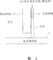
Fig. 2 is the mode chart of a variation of anode electrode in the manufacture method of carbon nanotube of expression embodiment of the present invention 1.
Fig. 3 is scanning electronic microscope (SEM) photo in the centre of the negative electrode stores that obtains of the manufacture method by the carbon nanotube of embodiment of the present invention 1.
Fig. 4 is the mode chart of arc-over situation between the carbon material electrode in the manufacture method of carbon nanotube of expression embodiment of the present invention 2.
Fig. 5 represents that hollow electrode hole sectional area and inner gas volume that flows through and electric arc produce the experimental result picture of the relation of form.
Fig. 6 is for the preparation method for carbon nano-tube of embodiment of the present invention 3 is described, expression is according to the photo of the scanning electronic microscope (SEM) at the cathode spot position of the generation situation of the different and different carbon nanotube of cathode preheat temperature.
Fig. 7 is for the preparation method for carbon nano-tube of embodiment of the present invention 3 is described, expression is according to the photo of the scanning electronic microscope (SEM) at the cathode spot position of the generation situation of the different and different carbon nanotube of cathode preheat temperature.
Fig. 8 is the manufacture method for the carbon nanotube that embodiment of the present invention 4 are described, expression is because of the synthetic result's of the different carbon nanotube of various carbon materials explanatory view.
Fig. 9 is the ultimate principle explanatory view of the manufacture method of the banded material of carbon nanotubes of the present invention and carbon nanotube.
Figure 10 is the formation mechanism explanatory view of carbon nanotube band.
Figure 11 is in the manufacture method of expression banded material that contains carbon nanotube of embodiment 5 and carbon nanotube, uses arc-over situation mode chart between the single anodic carbon material electrode.
Figure 12 is scanning electronic microscope (SEM) photo of carbon nanotube band.
Figure 13 is in the manufacture method of expression banded material that contains carbon nanotube of embodiment 5 and carbon nanotube, uses arc-over situation mode chart between a plurality of anodic carbon material electrodes.
Figure 14 is the mode chart that the field emission electrode of carbon nanotube band is used in expression.
Figure 15 is the mode chart that the field emission electrode of carbon nanotube band is used in expression.
Figure 16 is in the manufacture method of the banded material that contains carbon nanotube of embodiment 7 and carbon nanotube, the mode chart of expression carbon cathode heated by electrodes method.
Figure 17 is in the manufacture method of the banded material that contains carbon nanotube of embodiment 8 and carbon nanotube, the mode chart of expression carbon cathode heated by electrodes method.
Figure 18 is in the manufacture method of the banded material that contains carbon nanotube of embodiment 9 and carbon nanotube, the mode chart of expression product method of cooling.
Figure 19 is under the expression normal atmosphere, in argon gas atmosphere, and the mode chart of arc-over situation between the carbon material electrode (general discharge).
Figure 20 is when producing electric arc because of the general discharge short period of time, the result's that expression anticathode spot is observed scanning electronic microscope (SEM) photo.
Figure 21 is the mode chart of other embodiment of the manufacture method of the explanation field emission electrode that uses carbon nanotube.
Figure 22 is the mode chart of expression with the field emission electrode of the manufacture method manufacturing of Figure 21.
Figure 23 is in the field emission electrode made from the manufacture method of Figure 21, near the electron micrograph the junction surface of substrate and the banded material of peeling off.
Figure 24 is in the field emission electrode made from the manufacture method of Figure 21, the electron micrograph of taking from the top of having peeled off the release surface behind the banded material.
Figure 25 is in the field emission electrode made from the manufacture method of Figure 21, the electron micrograph that the release surface of having peeled off behind the banded material is vertically cut off demonstration.
Figure 26 is the mode chart of other embodiment of the manufacture method of the explanation field emission electrode that uses carbon nanotube.
Figure 27 is the mode chart of other embodiment of the manufacture method of the explanation field emission electrode that uses the carbon nanotube band.
Figure 28 is the field emission characteristic and the explanatory view of relatively representing according to the field emission electrode of existing method manufacturing of field emission electrode that this law is bright.
Specific embodiments
Below, according to illustrated embodiment explanation the present invention.
Figure 19 is under the expression normal atmosphere, in argon gas atmosphere, and the mode chart of arc-over situation between the carbon material electrode (general discharge), anode 1 uses bar-shaped carbon material, and negative electrode 2 uses the tabular carbon material.As shown in figure 19, under atmospheric pressure, in argon gas atmosphere, the position that electric arc produces is acutely change back and forth, violent irregular moving (among Figure 19,2 electric arc 3a, 3b of asynchronism(-nization) being illustrated simultaneously) also gone up at negative plate (tabular carbon material 2) in the position of cathode spot.The 4th, the negative electrode jet flow is that ionized part takes place carbon evaporation, the part carbon atom of negative electrode.Violent irregular the moving of such electric arc, under atmospheric pressure, obvious especially in the argon gas atmosphere, but under low pressure, also observe same trend in helium or the hydrogen atmosphere.
Figure 20 is when the short period of time produces electric arc by the general discharge of above-mentioned Figure 19, scanning electronic microscope (SEM) photo that expression anticathode spot is observed, (a) be the SEM photo at expression cathode spot centre and peripheral position thereof, (b) being the SEM photo in the cathode spot centre of amplification, (c) is the SEM photo at the cathode spot periphery position of amplification.By these SEM photos as can be known: the cathode spot centre has generated carbon nanotube thick and fast, and then only pile up at the peripheral position of opposite cathode spot amorphous (unformed) carbon piece.That is to say, to possess the condition of synthesizing carbon nanotubes at the cathode spot place of electric arc, at its peripheral position then be can not synthesizing carbon nanotubes condition.Can think by these results: in the violent irregular mobile general arc-over scheme of cathode spot, but cathode electrode is submitted the condition of the reciprocal existing synthesizing carbon nanotubes of appearing again and condition that can not synthesizing carbon nanotubes, therefore can only reclaim the more negative electrode stores that contains impurity such as agraphitic carbon.
Therefore we learn a kind of like this electrical arc: use axis part to have the hollow electrode 11 conducts anode that contains carbon material as shown in Figure 1 of hole 11a, in open space (under the normal atmosphere, in the air atmosphere), hole 11a by hollow electrode 11 inside supplies with a spot of argon gas to electric arc 3, this moment, electric arc 3 took place along air flow path, and its cathode spot also always produces in the position with respect to the gas squit hole.This can think that the degree of ionization of argon gas rises owing under the high temperature that produces at solid arc-over, and electroconductibility is compared increase with peripheral position, therefore produces electric arc along the argon gas stream path.In addition, also because the hollow electrode inner face contacts the stable easily anode spot that forms with rare gas element.As mentioned above, rare gas element such as argon gas and electron impact and the ionization efficiency height that produces provides the space that is easy to generate electric arc.Therefore, if after negative electrode 2 begins to supply with argon gas, produce electric arc 3, can be that constraint arc produces the path then by the electric arc generation initial stage by the hole 11a of hollow electrode 11 inside, can prevent that the irregular of cathode spot of electric arc on the negative electrode 2 from moving.The result, can produce the initial stage promptly at the preferential synthesizing carbon nanotubes in the generation position (centre of electric arc) of this cathode spot that is fixed from electric arc, can make highly purified multilayer carbon nanotube synthetic product in the generation position (centre of electric arc) of this cathode spot that is fixed.
Observe the negative electrode stores that these hollow electrode 11 static arc-overs obtain by scanning electronic microscope (SEM), can find that heart position is the cathode spot position therein, even electric arc is arranged for a long time, carbon nanotube that also can synthesis of high purity.Do not observe the illustrated negative electrode jet flow of above-mentioned Figure 19 in the static arc-over of hollow electrode 11, may be that the carbon steam that negative electrode 2 produces is spraying with the arc column position overlapped, infer thus,, also can improve the combined coefficient of carbon nanotube by improving the concentration of carbon atom in the electric arc.
The hollow anode electrode is not limited to carbon material, also can use non-consumable electrodes such as water-cooled copper electrode.
In addition,, for example also can use bar-shaped anode 111 shown in Figure 2, by disposing to such an extent that gas jet 112 flows to cathode electrode along the side of bar-shaped anode 111 separately about flowing to the rare gas element of negative electrode by anode or containing the mixed gas of rare gas element.As long as air-flow is laminar flow fully,, cathode spot is fixed even such mode also can produce electric arc along air-flow.About this, other embodiment described later also can be handled equally.
About hole 11a gas supplied by hollow electrode 11 inside, use pure argon might as well, or use mixed about 5% hydrogen and helium argon gas might as well, arc shape is not seen big variation.Particularly in argon gas, sneak into the hydrogen of the tens of % of several %-, can can't harm the stability of electric arc, increase the receipts amount of carbon nanotube.This may be to prevent that the carbon that distils from as clustering long effect, having created carbon nanotube synthetic condition on cathode electrode easily because hydrogen has on electrode.Suitable gas flow is subjected to the influence of sectional area of the hole 11a of hollow electrode 11, every 1mm
2The sectional area of hole 11a is 10-400ml/ minute.
Fig. 5 represents that hollow electrode hole sectional area and inner gas volume that flows through and electric arc produce the experimental result picture of the relation of form.As shown in Figure 5, if the pure argon of supplying with by the hole 11a of hollow electrode 11 or sneaked into about 5% hydrogen or the every 1mm of throughput ratio of the argon gas of helium
2The sectional area 10ml/ of hole 11a minute too much few, then can not give full play to the function of plasma gas; The every 1mm of throughput ratio
2More than the sectional area 400ml/ of hole 11a minute too much, what for also increase to the concentration of the plasma gas at electrode perimeter position, central part not only, peripheral position also forms the condition that is easy to generate arc-over, will become to make electric arc concentrated.
As the present embodiment, making the airshed of being supplied with by the hole 11a of hollow electrode 11 is 1mm
2The hole 11a sectional area of hollow electrode 11 10-400ml/ minute can be brought into play the function of plasma gas, and can create with peripheral position and compare, and has only the anode electrode central part to carry out the condition of arc-over easily.As a result, cathode spot is concentrated, but yield generate the high carbon nanotube of purity well.
Embodiment
The hollow electrode that uses external diameter 36mm, internal diameter 10mm is as anode electrode, at open space (under the normal atmosphere, in the air atmosphere), on one side supply with the argon gas that contains 3% hydrogen of 10 liters of/minute flows to cathode electrode by the hole of hollow electrode inside, with 500A electric current, 35V voltage (electric arc be about 5mm) carry out arc-over 1 minute on one side.
Fig. 3 is scanning electronic microscope (SEM) photo in the centre of the negative electrode stores that obtains of 1 minute static arc-over of this hollow electrode.Synthesized highly purified multilayer carbon nanotube in the centre of negative electrode stores as can be known by this photo.Obtained the highly purified multilayer carbon nanotube of several 10mg by this static arc-over of 1 minute.
Fig. 4 is the explanatory view of manufacture method of the carbon nanotube of embodiment of the present invention 2, among the figure, and the identical symbol of mark on the part identical with above-mentioned embodiment 1.
The manufacture method of the carbon nanotube of the present embodiment has following feature: as the anode that contains carbon material adopt with the anode of above-mentioned embodiment 1 same have the hollow electrode 11 of hole 11a at axis part, make simultaneously to be equipped with and sneak into as the catalyzer of the metal-powder of catalyzer or metallic compound 21 that container 22 is inner to be connected with the hole 11a of hollow electrode 11, at open space (under the normal atmosphere, in the air atmosphere) under, sneak into container 22 via catalyzer, spray into rare gas elementes such as a spot of argon gas to negative electrode 2 or contain the mixed gas of rare gas element by the hole 11a of hollow electrode 11 inside, simultaneously, with utilize this air-flow injecting catalyst metal-powder or metallic compound 21, and electric arc 3 is produced.
In the present embodiment, use pure argon sneaked into about 5% hydrogen or the argon gas of helium as hole 11a gas supplied by hollow electrode 11 inside.Particularly in argon gas, sneak into the hydrogen of the tens of % of several %-, can can't harm the stability of electric arc, increase the receipts amount of carbon nanotube.This may be to prevent that the carbon that distils from as clustering long effect, having created carbon nanotube synthetic condition on cathode electrode easily because hydrogen has on electrode.
In the present embodiment, same with above-mentioned embodiment 1, suitable gas flow is subjected to the hole 11a sectional area of hollow electrode 11 to influence 1mm
2The hole 11a sectional area of hollow electrode 11 is 10-400ml/ minute, if reach this suitable gas flow, then can bring into play the function of plasma gas, and can create with peripheral position and compare, have only the anode electrode central part to carry out the condition of arc-over easily.As a result, cathode spot is concentrated, but yield generate the high carbon nanotube of purity well.
About the kind of employed metal-powder or metal compound powders, as long as have catalyst function, can be any kind, adopted monomer or their mixtures such as Fe, Ni, Co, FeS here.
The present embodiment also is to be sprayed into rare gas element or contain the mixed gas of rare gas element to negative electrode by the hole 11a of hollow electrode 11 inside, therefore under the high temperature that produces because of arc-over, rare gas element or the degree of ionization that contains the mixed gas of rare gas element rise, electroconductibility is compared increase with peripheral position, in addition, at the stable anode spot that forms of hollow electrode inner face, therefore become the form that produces the constraint arc of electric arc along the argon gas stream path.
In the present embodiment, owing to be to utilize air-flow injecting catalyst metal-powder or metal oxide, catalyzer is able to the ultra micro granulation through arc heat, and as nuclear, single-layer carbon nano-tube is grown thus with it.That is to say, can make highly purified single-layer carbon nano-tube synthetic product at the generation position (centre of electric arc) and the peripheral position thereof of fixed cathode spot.
Embodiment 3
Fig. 6 and Fig. 7 are for the preparation method for carbon nano-tube of embodiment of the present invention 3 is described, expression is according to the photo of the scanning electronic microscope (SEM) at the cathode spot position of the generation situation of the different and different carbon nanotube of cathode preheat temperature.
In the process by the arc-over synthesizing carbon nanotubes, mainly be the carbon steam that produces by the anode carbon electrode and carbon ion to the diffusion of negative electrode one side, condensing by anode to the low cathode electrode surface of temperature, synthesizing carbon nanotubes (particularly multilayer carbon nanotube) thus.Therefore the temperature of negative electrode is low more, and then the speed of growth of carbon nanotube is fast more, and cathode material is so long as the thermotolerance electro-conductive material gets final product, and need not is carbon material.
But, the inventor's experimental result shows: only increase anodic carbon steam and carbon ion, can only generate the low product of synthetic ratio of carbon nanotube, the temperature that generates the negative electrode of carbon nanotube is remained on suitable temperature range, this is important for generating the high carbon nanotube of purity.Promptly show: constitute with the same electrode of above-mentioned embodiment 1 or embodiment 2 and condition under, discharge again after in advance cathode electrode being heated to 500-2000 ℃, then the temperature at cathode spot position is compared with the situation that does not have preheating, high temperature can be formed, and the high carbon nanotube of purity can be synthesized.
Promptly as can be known: under the condition that does not have preheating (Fig. 6 (a)), do not generate carbon nanotube; Under the condition of 500 ℃ of preheating temperatures (Fig. 6 (b)), generate carbon nanotube on a small quantity, pre-heat effect is not too arranged; Under the condition of 2000 ℃ (Fig. 7 (a)), generate carbon nanotube in a large number; Under the condition of 2500 ℃ (Fig. 7 (b)), the evaporation fierceness of negative electrode carbon, the receipts amount of carbon nanotube also reduces.
Embodiment 4
Fig. 8 is the manufacture method for the carbon nanotube that embodiment of the present invention 4 are described, expression is because of the synthetic result's of the different carbon nanotube of various carbon materials explanatory view.
For the carbon nanotube of synthesis of high purity and receipts amount, illustrated as above-mentioned embodiment 3, it to a certain degree is more favourable that the temperature of electric arc cathode spot on the cathode material is improved.Usually the scope of resistivity (=intrinsic resistance) about 500-2000 μ Ω cm of the carbon dioxide process carbon electrode that uses as electrode, but use carbon material during as cathode material with 4000 μ Ω cm or above resistivity, near the cathode spot of cathode material, form high current density during arc-over, therefore resistance heating makes near the high temperature that forms of cathode spot.Therefore, the effect same can be obtained, the high carbon nanotube of receipts amount and purity can be generated with preheating cathode.
Usually the thermal conductivity of the carbon dioxide process carbon electrode that uses as electrode is the scope of 50-200W/mK, and resistivity in the carbon material and thermal conductivity roughly are negative correlation.That is, resistivity is big, and then thermal conductivity is low, is difficult to heat conduction, and temperature is high more near the cathode spot.Resistivity is that the thermal conductivity of 4000 μ Ω cm or above carbon material is approximately 40W/mK or following.
Among Fig. 8, use contains carbonaceous, graphite matter, carbonaceous+various carbon material A-G such as graphite matter, with the above-mentioned the 1st or the same electrode of embodiment 2 constitutes and condition under carry out arc-over, with 3 grades (zero: good, △: general, *: poor) the receipts amount and the purity of evaluation gained carbon nanotube.As shown in Figure 8: common electrode, promptly resistivity (=intrinsic resistance) for about 500-2000 μ Ω cm, thermal conductivity is 40W/mK or above carbon material B, C, D, the purity difference of their carbon nanotube, the receipts amount is that carbon material B is poor, carbon material C, D are general.In addition, resistivity (=intrinsic resistance) surpasses 2000 μ Ω cm but is that carbon nanotube receipts amount and the purity of 40W/mK or above carbon material E is all general less than 4000 μ Ω cm, thermal conductivity.
Relative therewith, resistivity (=intrinsic resistance) is that 4000 μ Ω cm or above, thermal conductivity are 40W/mK or following carbon material A, F, G, and the receipts amount and the purity of its carbon nanotube have all obtained good result.
In above-mentioned each embodiment, be that example is illustrated, also can in container, carry out to carry out arc-over at open space (under the normal atmosphere, in the air atmosphere).Promptly, make in the container space opening to outside via surplus valve, make by surplus valve simultaneously that the space is set at the certain air pressure higher than normal atmosphere in the container, atmosphere is forced to import space in the container, create air atmosphere, spray on one side rare gas element such as argon gas to cathode electrode or contain the mixed gas of rare gas element, Yi Bian carry out arc-over betwixt by the inside that is arranged at the hollow electrode in the container.Also can in the low container of phase inverse ratio normal atmosphere, carry out arc-over in the space in addition.
Embodiment 5
Fig. 9 is the ultimate principle explanatory view of the manufacture method of the banded material of carbon nanotubes of embodiment of the present invention 5 and carbon nanotube.
As shown in Figure 9, use axis part to have the hollow electrode 11 of hole 11a as the anode that contains carbon material, in open space (under the normal atmosphere, in the air atmosphere), hole 11a by hollow electrode 11 inside supplies with a spot of argon gas to electric arc 3, when mobile hollow electrode 11 carries out arc-over on one side on one side, the centre of electric arc 3 (cathode spot) 3a generate banded material on the cathode electrode of process, confirm the phenomenon that their tools are peeled off naturally.Observe this band shape material by scanning electronic microscope (SEM) and transmission electron microscope (TEM), confirmation is that the aggregate by high-purity carbon nano tube constitutes.This band shape material is that the generating principle (formation mechanism) of high-purity carbon nano tube band (hereinafter referred to as high-purity C NT band) 31 can be thought as shown in figure 10.
Promptly, principle (mechanism) at the centre of electric arc 3 (cathode spot) 3a synthesizing carbon nanotubes is same with the situation of static electric arc, but under the situation of moving electric arc, position 3b generates agraphitic carbon 32 at the electric arc periphery, therefore shown in upper part of Figure 10, the product cross section of electric arc 3 moving portions is that the aggregate of carbon nanotube is by the form of agraphitic carbon 32 clampings.But, after electric arc 3 is gone over, under the condition of high temperature, be in contact with one another with atmosphere, therefore, preferentially oxidized, the burning of the agraphitic carbon 32 that crystal structure defects is many, a part is burnt (stage casing of Figure 10).And, after the process of cooling of cathode electrode 2 in because the layer of agraphitic carbon is different with the thermal expansivity of high-purity carbon nano tube aggregate, the phenomenon (hypomere of Figure 10) that generation high-purity carbon nano tube band shape is peeled off.Like this, by the moving electric arc discharge of hollow electrode 11, the carbon nanotube of synthesis of high purity simultaneously, can reclaim the aggregate of zonal high-purity carbon nano tube easily efficiently.
Embodiment
Same with above-mentioned embodiment 1, the hollow electrode that uses external diameter 36mm, internal diameter 10mm is as anode electrode, at open space (under the normal atmosphere, in the air atmosphere), on one side supply with the argon gas that contains 3% hydrogen of 10 liters of/minute flows to cathode electrode by the hole of hollow electrode inside, with 500A electric current, 35V voltage (electric arc be about 5mm) carry out arc-over 1 minute on one side.
Photo as above-mentioned Fig. 3 (a) scanning electronic microscope (SEM) (b) is illustrated, by this static arc-over of 1 minute, has synthesized the highly purified multilayer carbon nanotube of several 10mg in the centre of negative electrode stores.
Then, the synthetic method of having represented this high-purity C NT band 31A among Figure 11.The hollow carbon electrode 11 that uses external diameter 10mm, internal diameter 4mm is as anode electrode, and the cylindric carbon dioxide process carbon electrode 2A that uses diameter 35mm is as cathode electrode.Make the cathode electrode rotation, hollow carbon electrode 11 is moved along the axial direction due straight line of cathode electrode, cathode spot is drawn spiral-line and is moved on cathode electrode.The speed of rotation of cathode electrode is 1.5 rev/mins, and the translational speed of hollow carbon electrode (anode motor) 11 transverse directions (representing with arrow among Figure 11) is 35mm/ minute, and the translational speed that the electric arc on the cathode electrode produces point is about 170mm/ minute.In addition, carry out arc-over at open space (under the normal atmosphere, under the air atmosphere), use pure argon by the hollow electrode gas supplied, flow is 1 liter/minute.Discharging condition is electric current 100A, voltage 20V (electric arc is about 1mm).Behind the arc-over, on the spirrillum position of moving on the cathode electrode, the about 2-3mm of width, the about 100 microns banded high-purity C NT of thickness have been synthesized in cathode spot.The width and the thickness of this CNT band can change according to shape, size and the synthesis condition of electrode.Figure 12 (a) (b) represents the SEM photo of synthetic high-purity C NT band.Belt surface is attached with the spherical agraphitic carbon about 1 micron, but inner aggregate by highly purified carbon nanotube constitutes.Can change places by the heat treatment vessel under the oxidizing atmosphere and remove the agraphitic carbon of this amount.
Figure 13 represents the synthetic method of two high-purity C NT bands 31A, 31B.Two hollow carbon electrode 11A, 11B using external diameter 10mm, internal diameter 4mm are as anode electrode, and the cylindric carbon dioxide process carbon electrode 2A that uses diameter 35mm separately is as cathode electrode.Make the cathode electrode rotation, hollow carbon electrode 11A, 11B are all moved along the axial direction due straight line of cathode electrode, cathode spot is drawn two spiral-linees and is moved on cathode electrode, and pitch is identical.In addition, carry out arc-over at open space (under the normal atmosphere, under the air atmosphere), use pure argon by the hollow electrode gas supplied, flow is respectively 1 liter/minute.Discharging condition is electric current 100A, voltage 20V (electric arc is about 1mm).
In the synthetic method of the high-purity C NT of Figure 11 of single anode electrode band, as described above, the suitable relative moving speed that electric arc produces point is about 170mm/ minute, but in the synthetic method of the high-purity C NT of Figure 13 of a plurality of anode electrodes band, the suitable relative moving speed of electric arc generation point is about 1.8 times of single anode electrode situation, promptly 310mm/ minute.This may be because two thermals source influence each other, and for obtaining suitable temperature experience, the relative moving speed of electrode is compared with the situation of single anode electrode and is about 1.8 times.Be accompanied by the increase of this preheating and degree of heat, the relative moving speed that generates the best electric arc generation point of banded material has the raising phenomenon, and this also observes in other embodiment described later and obtains.
The factor of the temperature experience that influences cathode surface is carried out various changes to be studied, the result learns: for realizing the present invention, if the relative moving speed that above-mentioned electric arc produces point in the scope of 50mm/ minute-500mm/ minute, the further preferred relative moving speed scope at 100mm/ minute-350mm/ minute, then can generate the intensive banded material of extremely good carbon nanotube in the scope of 10mm/ minute-1000mm/ minute, preferred relative moving speed.Move slowly for the utmost point of relative moving speed,, also be difficult to obtain the temperature experience of suitable scope even the factor that influences cathode surface temperature experience is carried out various changes less than 10mm/ minute.That is, if set electric arc heat input etc. for the peak temperature that obtains to stipulate, then Zhi Hou speed of cooling significantly reduces, and the carbon nanotube of generation is exposed under the high temperature for a long time, purity drop.In addition, when relative moving speed surpasses 1000mm/ minute, be difficult to obtain the temperature experience of proper range too.That is, for example the peak temperature in order to obtain to stipulate must be imported the bigger of setting with the electric arc heat of unit time, and like this, anodic consumption is remarkable, is difficult to long-play.Near peak temperature the residence time shortens in addition, and the thickness of the carbon nanotube of generation also becomes as thin as a wafer, can't generate banded material.
In the synthetic method of the high-purity C NT band of Figure 11 of single anode electrode, under the state that the straight line that stops hollow carbon electrode 11 moves, make cathode electrode---cylindrical carbon electrode 2A rotation, on same circumference, back and forth discharge, then within a circle, cathode electrode generates zonal carbon nanotube continuously, but after the 2nd circle, though the generation carbon nanotube can be used as the banded ratio that reclaims and sharply reduces.This may be owing in the discharge of the 1st circle, and the negative electrode material at discharge track position changes, and for example the heat of discharge generation has promoted greying, and resistivity reduces or Heat conductivity increases, and the 2nd all later temperature are through having bigger variation all through the ages; And in the discharge of the 1st circle, oxidation takes place in the cathode material surface, and surfaceness increases, and is difficult to be band shape and peels off.Relative therewith, hollow carbon electrode 11 straight lines are moved, the track that makes arc-over is that spirrillum is moved, and when cathode spot can be positioned at once more once formed on the cathode surface cathode spot regional, all can synthesize and collect zonal carbon nanotube on the whole track of discharge happening part.Rotten and the surface oxidation of the cathode material that arc-over causes also takes place near the discharge happening part, thus between the preferred trajectories at interval 4mm or more than, more preferably 8mm or more than.Like this, do not relatively move across, can stablize synthetic zonal carbon nanotube by the track that makes arc-over happening part on the cathode surface.Therefore the rotten position that the thermal conductance of negative electrode causes is only limited to upper layer, can cut or rotten part is easily removed in grinding etc. by grinding, and can reuse afterwards.
Figure 14 and Figure 15 are the mode charts of the field emission electrode of the expression CNT band that uses the present embodiment.Contain carbon nanotube banded material 31 carbon nanotube the purity height and with the unprocessed state in synthetic back, be that every carbon nanotube has only part to join, the state that keeps its pencil, can present uniform film like, therefore can directly be sandwiched between the substrate 50,50, or directly be pasted on substrate 50 or the electrode, as high performance field emission electrode.For example, can be with 50,50 clampings of two substrates of banded material 31 usefulness, make the form that an end of banded material 31 exposes.Perhaps can banded material be pasted on it, need not to carry out surface treatment etc. afterwards, therefore can reduce manufacturing process and reduce production costs at the one side coating conductive adhesive of substrate 50.Here, conductive adhesive 51 can use conductive paste of metal-powders such as silver, nickel or aluminium or powdered graphite and solvent etc.The solvent height, then the viscosity of paste reduces, and the figure slurry infiltrates the fine position of banded material 31 by capillarity, makes the carbon nanotube that constitutes band be pencil and assembles.The carbon nanotube of belt surface is pencil and assembles, if then do not carry out some surface treatments, just can not get good field emission characteristic.For preventing such problem, preferably use viscosity height, paste that solvent is low to paste banded material 31.Even the paste that viscosity is high also has the inside that some are penetrated into band, but the short of carbon nanotube that is penetrated into banded material 31 surfaces then is unlikely to influence field emission characteristic.Can also be to paste banded material 31 with paste, and with the form of substrate clamping.
Like this, by using the intensive banded material 31 of carbon nanotube, can performance carbon nanotube easy to manufacture simply as the field emission electrode of the characteristic of electron source.
Figure 21 is the mode chart of other embodiment of the manufacture method of the explanation field emission electrode that uses the CNT band.Among this embodiment, the banded material 110 that contains carbon nanotube between two substrates 121,122, is attached to this substrate 121,122 by peeling off by cramping then.
At first, the banded or lamellated banded material 110 about thickness 50-500 μ m is disposed at (Figure 21 (a)) between a pair of substrate 121,122.Then clamp banded material 110 and pressurization (Figure 21 (b)).Again a pair of substrate 121,122 is pulled away from (Figure 21 (c)).
At this moment, it is 2 that banded material 110 is stripped from thickness direction, is attached with the banded material 111,112 (hereinafter referred to as banded release material) of being stripped from the substrate 121,122 respectively.That is the field emission electrode 142 of, form the field emission electrode 141 formed by substrate 121 and banded release material 111 respectively, forming by substrate 122 and banded release material 112.
Metal, metallic compound and the various materials such as isolator glass or resin that can use electroconductibility are as baseplate material.
Figure 22 is the mode chart of expression with the field emission electrode of the manufacture method manufacturing of above-mentioned Figure 21.The identical symbol of mark on the part identical with Figure 21.
Be attached with banded release material 111 (attachment surface is 111B) on the substrate 121, on the surperficial 111T of banded release material 111, carbon nano-tube fibre is burr shape (below specify).
The junction surface
Figure 23 is with near substrate 121 electron micrograph with the junction surface 111B of banded release material 111 in the field emission electrode of the manufacture method manufacturing of above-mentioned Figure 21, be with adhesive tape sticking on the release surface 111T of the banded release material that obtains by above-mentioned processing, draw back this adhesive tape then, substrate 121 is cut off grind.
The result of ultimate analysis shows: the white portion of photo central part is a carbon nano-tube fibre, and its downside is an aluminium base.Under with this degree of tape stripping, the carbon nano-tube fibre of the overwhelming majority all residues on the surface of substrate 121.
Promptly demonstrate: carbon nano-tube fibre and substrate 121 are seamlessly closely pasted, and carbon nano-tube fibre is bigger than the bond strength of carbon nano-tube fibre and adhesive tape with the bond strength of substrate.
And the aluminium base before engaging is concave-convex surface 0.1 μ m or following mirror finish product, but concavo-convex whole the increasing about number μ m in pressurization back, pressurization causes the distortion that substrate is small.Can infer thus: pressurization makes the contact area with carbon nano-tube fibre increase and closely attaches, and carbon nano-tube fibre produces the embedding phenomenon with this substrate, also has the state of so-called mechanical engagement.
Thereby can think that the principle of adhering to of carbon nanotube and substrate 121,122 is a kind of being selected from below in conjunction with power or various bonding force combined action: by pressurization, part carbon nanotube enters in substrate 121,122 material surfaces concavo-convex, by taking place, the mechanicalness hook produces bonding force, promptly so-called " principle of casting anchor " (mechanical bond); Substrate 121,122 material surfaces distortion, carbon nanotube embed and the same effect that produces deeply; The part carbon atom that constitutes carbon nanotube engages with the atom bonded chemical of substrate 121,122; And the physical property combination of Van der Waals force etc.
Release surface
Figure 24 and Figure 25 are the electron micrographs of the release surface 111T of banded release material 111 in the above-mentioned manufacture method shown in Figure 21 of expression, and Figure 24 is the photo by the being seen release surface 111T in top, and Figure 25 is the photo that vertically cuts off release surface 111T.
Among Figure 24 and Figure 25, the featheriness pattern of carbon nano-tube fibre laminar surface has been carried out comprehensive observation.Observe penniform position by horizontal direction, carbon nano-tube fibre is the burr shape and stretches to open space.Infer that carbon nano-tube fibre entangled to each other is broken by above-mentioned manufacture method.
That is to say that the every carbon nano-tube fibre that constitutes banded material constitutes band in intricately one side entangled to each other on one side.Carbon nanotube has one, and to be compressed be mutual accumulative character, and therefore, carbon nanotube is assembled during pressurization, but this aggregation force than with the sticking power of substrate a little less than.Therefore, can think that the pressurization back is as being pulled away from substrate 121,122, then be attached to carbon nano-tube fibre entangled to each other on the substrate 121,122 and broken (being stripped from), cut off by this aggregate site, therefore this cut carbon nano-tube fibre be pulled away from that direction is parallel to be orientated (perpendicular to the relative face of substrate 121,122).
In a word, can infer the carbon nano-tube fibre that constitutes banded material 110, its length sufficiently long, and intricately is entangled to each other, and thus, after being pulled away from, release surface 111T, 112T have the form of burr.
Thereby, can guarantee the attachment surface 111B of substrate 121,122 and banded release material 111,112, the electroconductibility of 112B, and can make the field emission electrode of the electron emission characteristic excellence of release surface 111T, 112T simply.
Promptly, can be arranged at the state that does not add any processing after being stripped from electrical equipment or the electronic installation, therefore by using the intensive banded material of carbon nano-tube fibre, can make the field emission electrode of pasting as the form of electron source characteristic with easy performance carbon nanotube simply.
Figure 26 is the mode chart of other embodiment of the manufacture method of the explanation field emission electrode that uses the CNT band, the identical symbol of mark on the part identical with above-mentioned Figure 21.
This embodiment be basically will contain carbon nanotube banded material 110 crampings between two substrates 122,123, by peeling off it is attached on this substrate 121,123 then.But one of them substrate 123 is made of the material higher than the deformation performance of another substrate 122 (below become deformed plate).At first, banded material 110 is disposed at (Figure 26 (a)) between substrate 122 and the deformed plate 123.Then, banded material 110 of clamping and pressurization (Figure 26 (b)).Again substrate 122 and deformed plate 123 are pulled away from (Figure 26 (c)).
At this moment, it is 2 that banded material 110 is stripped from thickness direction, is attached with banded material 112,113 on substrate 121 and the deformed plate 123 respectively.
That is the deformed plate that is attached with banded material 143 of, form the field emission electrode 142 formed by substrate 122 and banded release material 112 respectively, forming by deformed plate 123 and banded release material 113.
The surface of deformed plate 123 is out of shape because of pressurization, therefore on the surface of the deformed plate 143 that is attached with banded material, forms ridge 124 around banded release material 113.That is, plastic flow takes place in deformed plate 123, and feasible substrate 122 to opposite side has played the evenly effect of pressurization of its surface that makes.The result can obtain not having and adhere to uneven, more uniform carbon nanotube attachment surface 112B.
Particularly, even the surface of substrate 122 is not fully level and smooth, for the relatively more outstanding part of substrate 122 and relatively the arbitrary portion of the part of depression all can evenly pressurize, so can be adhered to uniformly.Thereby when being stripped from, attachment surface 112B can partly not peeled off from the surface of substrate 122.Promptly guaranteed the uniform adhesion strength of attachment surface 112B.
During by the synthetic banded material 110 of arc-over, banded material 110 is positioned at the face of anode one side than the strong adhesion (cathode electrode one side of banded material is attached with the carbon material of some negative electrodes, and the purity of carbon nanotube is also poor than anode one side) in the face of substrate that is positioned at negative electrode one side.In addition, the deformed plate 123 that deformation performance is big is than substrate 122 strong adhesions.Therefore, the face of banded material 110 anodes one side is disposed at substrate 122 1 sides, the face of negative electrode one side is disposed at deformed plate 123 1 sides, the adhesion strength that then can obtain each face becomes about equally (their difference diminishes), and does not adhere to inequality, more uniform carbon nanotube attachment surface 122B on the substrate 122.
Metal, metallic compound and the various materials such as isolator glass or resin that can use electroconductibility are as baseplate material 122.
For example, when using stainless steel disk (for example diameter 5mm), can use the indium piece as deformed plate 123 as substrate 122.Perhaps use lead, scolding tin, aluminium etc. also can obtain identical result.
Figure 27 is the mode chart of other embodiment of the manufacture method of the explanation field emission electrode that uses the CNT band, the identical symbol of mark on the part identical with above-mentioned Figure 26.
Among this embodiment, at first as Figure 27 (a), respectively the plan view shape of substrate 122, deformed plate 123 and banded material 110 is made roughly the samely, they are arranged in the former 150 (being equivalent to die head) with through hole identical with this plan view shape.
Then, shown in Figure 27 (b), with 160 extruding of the 123 usefulness punch presses of the deformed plate in the former 150.At this moment, the exterior contour of deformed plate 123 is subjected to former 150 restrictions, and therefore the not redeformation of outline direction has positively guaranteed the pressurization to banded material 110.
Afterwards, shown in Figure 27 (c), substrate 122 and deformed plate 123 are pulled away from.Thus with above-mentioned Figure 26 similarly, form the field emission electrode of forming by substrate 122 and banded release material 112 attached to it 142, the deformed plate of forming by deformed plate 123 and banded release material 113 attached to it that is attached with banded material 143.
Like this, banded material 110 is clamped from both sides by the substrate 122 identical with its planeform and deformed plate 123, be disposed in the former 150 with through hole identical with its planeform, with punch press 160 extruding, can obtain 123 outer more uniform the adhering to that Monday, side was not swelled because of pressurizing and deformation, its surface of deformed plate.Peel off usually and outside former 150, carry out.
Figure 28 is field emission characteristic and the existing method result relatively of field emission electrode of the present invention, compared in the vacuum with field emission electrode as negative electrode, with anodic apart from being 0.1mm, obtaining predetermined electric current density (10mA/cm
2) time impressed voltage.
Compare with existing method, the impressed voltage of susceptible of proof field emission electrode of the present invention when obtaining predetermined electric current density especially reduces, and the electron emission energy is high.
That is, the impressed voltage that has printed the field emission electrode of the paste that contains the powder formed carbon nanotube is 680V, and the impressed voltage of pasting the field emission electrode of banded material is 440V.And the impressed voltage of the field emission electrode that the method for clamping carbon nanotube is made between the method for clamping carbon nanotube and substrate and the deformed plate between the substrate is 210V and 192V, and the susceptible of proof electron emission capability is improved.
Embodiment 6
Moving that the electric arc generation is put on the cathode electrode that causes by relatively moving of electrode added in the ultimate principle of the banded material that contains carbon nanotube of embodiment of the present invention 6 and the manufacture method of carbon nanotube such as the explanation of above-mentioned Fig. 4.
Promptly, as shown in Figure 4, the banded material that contains carbon nanotube of the present embodiment and the manufacture method of carbon nanotube have following feature: the anode that contains the anode of carbon material and above-mentioned embodiment 5 is same, adopt axis part to have the hollow electrode 11 of hole 11a, connecting simultaneously to be equipped with and sneaking into the inner hole 11a with hollow electrode 11 of container 22 as the catalyzer of the metal-powder of catalyzer or metallic compound 21, at open space (under the normal atmosphere, in the air atmosphere) under, sneak into container 22 via catalyzer, spray into rare gas elementes such as a spot of argon gas to negative electrode 2 or contain the mixed gas of rare gas element by the hole 11a of hollow electrode 11 inside, simultaneously, utilize this air-flow injecting catalyst metal-powder or metal compound powders 21, carry out arc-over while hollow electrode 11 is relatively moved with respect to negative electrode carbon dioxide process carbon electrode 2.
Also be to use pure argon in the present embodiment or sneaked into about 5% hydrogen or the argon gas of helium as hole 11a gas supplied by hollow electrode 11 inside.Particularly in argon gas, sneak into the hydrogen of the tens of % of several %-, can can't harm the stability of electric arc, increase the receipts amount of carbon nanotube.This may be to prevent that the carbon that distils from as clustering long effect, having created carbon nanotube synthetic condition on cathode electrode easily because hydrogen has on electrode.
In the present embodiment, same with above-mentioned embodiment 5, suitable gas flow is subjected to the sectional area of the hole 11a of hollow electrode 11 to influence 1mm
2Hole 11a sectional area is 10-400ml/ minute, if reach this suitable gas flow, then can bring into play the function of plasma gas, and can create with peripheral position and compare, and has only the anode electrode central part to carry out the condition of arc-over easily.The result can make cathode spot concentrate, but yield generates the high carbon nanotube of purity well.
About the metal-powder that uses in the present embodiment or the kind of metal compound powders, then can be any kind as long as have catalyst function, adopted monomer or their mixtures such as Fe, Ni, Co, FeS here.
The present embodiment also is to be sprayed into rare gas element or contain the mixed gas of rare gas element to electric arc 3 by the hole 11a of hollow electrode 11 inside, therefore under the high temperature that produces because of arc-over, rare gas element or the degree of ionization that contains the mixed gas of rare gas element rise, electroconductibility is compared increase with peripheral position, in addition, at the stable anode spot that forms of hollow electrode inner face, therefore become the form that produces the constraint arc of electric arc along the argon gas stream path.
In the present embodiment, owing to be to utilize air-flow injecting catalyst metal-powder or metal oxide, so catalyzer is able to the ultra micro granulation through arc heat, and as nuclear, single-layer carbon nano-tube is grown thus with it.That is to say, can make highly purified single-layer carbon nano-tube synthetic product at the generation position (centre of electric arc) and the peripheral position thereof of fixed cathode spot.In addition, on one side mobile hollow electrode 11 carry out arc-over on one side, same with the explanation of above-mentioned Fig. 9, the centre of electric arc 3 (cathode spot) can generate the banded material 31 that contains the high purity single-layer carbon nano-tube on the cathode electrode of process.
Embodiment 7
Figure 16 is the explanatory view of the manufacture method of the banded material that contains carbon nanotube of embodiment 7 and carbon nanotube, among the figure, and the identical symbol of mark on the part identical with Figure 11 of above-mentioned embodiment 5.
The carbon nanotube that is undertaken by arc-over synthetic mainly is to be spread to negative electrode by carbon steam and carbon ion that the anode carbon electrode produces, and be condensing to the low cathode electrode surface of temperature by anode, thus synthesizing carbon nanotubes (particularly multilayer carbon nanotube).Therefore the temperature of negative electrode is low more, and then the speed of growth of carbon nanotube is fast more, and cathode material is so long as the thermotolerance electro-conductive material gets final product, and need not is carbon material.
But, the inventor's experimental result shows: only increase anodic carbon steam and carbon ion, can only generate the low product of synthetic ratio of carbon nanotube, the temperature that generates the negative electrode of carbon nanotube is remained on suitable temperature range, this is important for generating the high carbon nanotube of purity.Promptly, as can be known constitute with the same electrode of above-mentioned embodiment 5 or embodiment 6 and condition under, as shown in figure 16, with whole cathode electrode 2A by other power supply (AC power) heating of switching on, carry out arc-over afterwards again, then can make the temperature height of the temperature at cathode spot position, and can synthesize the banded material that contains the high carbon nanotube of purity than the situation that does not have preheating.
Like this, for the carbon nanotube of synthesis of high purity and receipts amount, the temperature at cathode spot position is improved to a certain degree, this is favourable.Usually the scope of resistivity (=intrinsic resistance) about 500-2000 μ Ω cm of the carbon dioxide process carbon electrode that uses as electrode, but use carbon material during as cathode material with 4000 μ Ω cm or above resistivity, near the cathode spot of cathode material, when arc-over, form high current density, therefore resistance heating makes near the high temperature that forms of cathode spot.For this reason, the effect same can be obtained, the high carbon nanotube of receipts amount and purity can be generated with heated cathode.
Usually the thermal conductivity of the carbon dioxide process carbon electrode that uses as electrode is the scope of 50-200W/mK, and resistivity in the carbon material and thermal conductivity roughly are negative correlation.That is, resistivity is big, and then thermal conductivity is low, is difficult to heat conduction, and therefore near the temperature of cathode spot is high more.Resistivity is that the thermal conductivity of 4000 μ Ω cm or above carbon material is approximately 40W/mK or following.
Embodiment 8
Figure 17 is the explanatory view of the manufacture method of the banded material that contains carbon nanotube of embodiment 8 and carbon nanotube, among the figure, and the identical symbol of mark on the part identical with Figure 11 of above-mentioned embodiment 5.
The banded material that contains carbon nanotube of the present embodiment and the manufacture method of carbon nanotube are as follows: as shown in figure 17, constitute with the same electrode of above-mentioned embodiment 5 or embodiment 6 and condition under, by heating, carry out arc-over simultaneously from the laser beam of laser oscillator the place ahead part to electric arc in the cathode spot of electric arc 3 or the electric arc track on the cathode electrode 2A.
The present embodiment can make the temperature height of the temperature at cathode spot position than the situation that does not have heating, and can synthesize the banded material that contains the high carbon nanotube of purity.
Embodiment 9
Figure 18 is the explanatory view of the manufacture method of the banded material that contains carbon nanotube of embodiment 9 and carbon nanotube, among the figure, and the identical symbol of mark on the part identical with Figure 11 of above-mentioned embodiment 5.
The banded material that contains carbon nanotube of the present embodiment and the manufacture method of carbon nanotube are as follows: as shown in figure 18, constitute with the same electrode of above-mentioned embodiment 5 or embodiment 6 and condition under, the product that is generated on the cathode spot track of electric arc 3 by gas jet is that high-purity C NT is with 3A to spray into gas.
By after generating banded material, making the product cooling, can promote peeling off of banded material to the jet body of product.Jet body so long as except that inflammable gas the getting final product of tool cooling performance, can make arbitrary gas such as air, nitrogen.Banded material is film like and generates on negative electrode 2A, by jet body, the temperature of cathode electrode 2A is reduced rapidly, and the thermal stresses between banded material and the cathode electrode works, and can significantly promote to peel off.
And, when jet body contains aerobic, even perhaps oxygen-free but under air atmosphere, bring oxygen into by jet body, have the thin skin of the polycrystalline graphite that promotes to be attached to outside in the product and agraphitic carbon or particulate oxidation, incendiary effect, the purity of the carbon nanotube of the banded material of result is improved, and the sticking power of negative electrode and banded material weakens simultaneously, promotes peeling off of banded material.
The sticking power of negative electrode and banded material is according to surface profile arithmetic average deviation (Ra) change of cathode material.That is, when the surfaceness of cathode material is thick (profile arithmetic average error (Ra) be 4.0 μ m or when above), the sticking power of banded material and negative electrode improves, and becoming is not easy to peel off.Therefore by employing surface profile arithmetic average deviation (Ra) be 3.2 μ m or following carbon material as cathode electrode, can weaken the sticking power of negative electrode and banded material, peel off naturally by thermal stresses, can make the recovery of banded material very easy.
Claims (42)
1. the banded material that contains carbon nanotube, this band shape material generates by arc discharge method.
2. the banded material that contains carbon nanotube, the thick 10-500 μ of this band shape material m, wide 1-10mm and have random length mainly have the flocculence aggregate of carbon nanotube.
3. the banded material that contains carbon nanotube, this band shape material is to form the arc-over path along the air-flow of being supplied with to the cathode electrode that contains carbon material by anode electrode, by moving the relative position of two electrodes, the cathode spot of electric arc is moved and synthetic on cathode material simultaneously.
4. the banded material that contains carbon nanotube, this band shape material is to produce electric arc along the air-flow of being supplied with to the cathode electrode that contains carbon material by the anode electrode inside of hollow, by moving the relative position of two electrodes, the cathode spot of electric arc is moved and synthetic on cathode material simultaneously.
5. the banded material that contains carbon nanotube, this band shape material be along by the anode electrode inside of hollow to the cathode electrode that contains carbon material, produce electric arc with the air-flow of supplying with as the metal-powder or the metallic compound of catalyzer, by moving the relative position of two electrodes, the cathode spot of electric arc is moved and synthetic on cathode material simultaneously.
6. as each described banded material that contains carbon nanotube among the claim 1-5, wherein arc-over carries out under air atmosphere.
7. as each described banded material that contains carbon nanotube among the claim 3-6, the mixed gas that wherein uses argon gas or argon gas and hydrogen as by anode electrode to the cathode electrode gas supplied.
8. as each described banded material that contains carbon nanotube among the claim 1-7, this material is that two electrodes are relatively moved and synthetic, wherein said move to make except electric arc produce and end position near, make electric arc on the cathode surface produce point and experience through a roughly the same temperature.
9. as each described banded material that contains carbon nanotube among the claim 1-8, it is characterized in that: this material is that two electrodes are moved and synthetic, and wherein said moving has following condition: cathode spot can not be positioned at the zone that had once formed cathode spot on the cathode surface once more.
10. as each described banded material that contains carbon nanotube among the claim 1-9, this material is on one side the place ahead part of electric arc in the cathode spot of whole cathode electrode or electric arc or the electric arc track on the cathode electrode to be heated the synthetic Yi Bian carry out arc-over.
11. as each described banded material that contains carbon nanotube among the claim 1-10, it is that 40W/mK or following carbon material are as cathode electrode and synthetic that this band shape material is to use resistivity 4000 μ Ω cm or above or thermal conductivity.
12. as each described banded material that contains carbon nanotube among the claim 1-11, it is that 3.2 μ m or following carbon material are as cathode electrode and synthetic that this band shape material is to use surface profile arithmetic average deviation (Ra).
13. as each described banded material that contains carbon nanotube among the claim 1-12, this band shape material is in the process of cooling of carrying out immediately behind arc-over, the product that generates on the cathode spot track of electric arc sprays into gas and synthetic.
14. field emission electrode, this electrode with above-mentioned be clipped in the middle of the substrate or be pasted on the substrate as each described banded material that contains carbon nanotube among the claim 1-13 make.
15. field emission electrode, this electrode is to be sandwiched between the substrate or substrate and than between the high material of this substrate deformation performance with above-mentioned as each described banded material that contains carbon nanotube among the claim 1-13, the pressurization post-tensioning from, the above-mentioned banded material of being stripped from is attached on the aforesaid substrate.
16. field emission electrode as claimed in claim 15 is characterized in that: as each described banded material clamping that contains carbon nanotube among the claim 1-13, the face that is positioned at anode one side when making it synthetic contacts with aforesaid substrate with above-mentioned.
17. the manufacture method of field emission electrode is characterized in that: invest on the substrate as each described banded material folder that contains carbon nanotube among the claim 1-13 above-mentioned, or be pasted on the substrate with conductive adhesive.
18. the manufacture method of field emission electrode, it is characterized in that: be sandwiched between the substrate or substrate and as each described banded material that contains carbon nanotube among the claim 1-13 than between the high material of this substrate deformation performance with above-mentioned, the pressurization post-tensioning from, the above-mentioned banded material of being stripped from is attached on the aforesaid substrate.
19. the manufacture method of field emission electrode as claimed in claim 18 is characterized in that: sandwich above-mentionedly as each described banded material that contains carbon nanotube among the claim 1-13, the face that is positioned at anode one side when making it synthetic contacts with aforesaid substrate.
20. the manufacture method of carbon nanotube is characterized in that: form the arc-over path along the air-flow of supplying with to the cathode electrode that contains carbon material by anode electrode.
21. the manufacture method of carbon nanotube, it is characterized in that: during by the arc-over synthesizing carbon nanotubes, anode electrode uses hollow electrode, on one side spray into rare gas element or contain the mixed gas of rare gas element to the cathode electrode that contains carbon material, therebetween make the electric arc generation on one side by the inside of hollow electrode.
22. the manufacture method of carbon nanotube is characterized in that: along forming the arc-over path to the cathode electrode that contains carbon material with the air-flow of supplying with as the metal-powder or the metallic compound of catalyzer by anode electrode.
23. the manufacture method of carbon nanotube, it is characterized in that: during by the arc-over synthesizing carbon nanotubes, anode electrode uses hollow electrode, on one side by the inside of hollow electrode to the cathode electrode that contains carbon material with spraying into rare gas element as the metal-powder of catalyzer or metal compound powders or containing the mixed gas of rare gas element, make the electric arc generation on one side betwixt.
24. the manufacture method as each described carbon nanotube among the claim 20-23 is characterized in that: under air atmosphere, carry out arc-over.
25. the manufacture method as each described carbon nanotube in the claim 21,23,24 is characterized in that: make rare gas element that sprays into to cathode electrode by the inside of hollow electrode or the flow of the mixed gas that contains rare gas element be: 1mm
2The hole sectional area of hollow electrode is 10-400ml/ minute.
26. the manufacture method as each described carbon nanotube among the claim 20-25 is characterized in that: the mixed gas that uses argon gas or argon gas and hydrogen is as rare gas element or contain the mixed gas of rare gas element.
27. the manufacture method as each described carbon nanotube among the claim 20-26 is characterized in that: when carrying out arc-over, cathode electrode is heated to 500-2000 ℃ in advance.
28. the manufacture method as each described carbon nanotube among the claim 20-27 is characterized in that: use resistivity 4000 μ Ω cm or above or thermal conductivity as 40W/mK or following carbon material as cathode electrode.
29. the manufacture method of carbon nanotube, it is characterized in that: during by the arc-over synthesizing carbon nanotubes, form the arc-over path along rare gas element of supplying with to the cathode electrode of carbonaceous material by anode electrode or the mixed gas flow that contains inert gas, by moving the relative position of two electrodes, the cathode spot of electric arc is moved on cathode material simultaneously.
30. the manufacture method of carbon nanotube, it is characterized in that: during by the arc-over synthesizing carbon nanotubes, anode electrode uses hollow electrode, on one side spray into rare gas element or contain the mixed gas of rare gas element to the cathode electrode that contains carbon material by the inside of hollow electrode, electric arc is produced, move the relative position of two electrodes simultaneously, the cathode spot of electric arc is moved on cathode material.
31. the manufacture method of carbon nanotube, it is characterized in that: during by the arc-over synthesizing carbon nanotubes, anode electrode uses hollow electrode, on one side by the inside of hollow electrode to the cathode electrode that contains carbon material with spraying into rare gas element as the metal-powder of catalyzer or metal compound powders or containing the mixed gas of rare gas element, electric arc is produced, by moving the relative position of two electrodes, the cathode spot of electric arc is moved on cathode material simultaneously.
32. manufacture method as each described carbon nanotube among the claim 29-31, it is characterized in that: by moving of two electrode relative positions, the cathode spot that makes electric arc relatively moves with the velocity range of 10mm/ minute-1000mm/ minute on the cathode material surface.
33. the manufacture method as each described carbon nanotube among the claim 29-32 is characterized in that: under air atmosphere, carry out arc-over.
34. the manufacture method as each described carbon nanotube among the claim 30-33 is characterized in that: make rare gas element that sprays into to cathode electrode by the inside of hollow electrode or the flow of the mixed gas that contains rare gas element be: 1mm
2The hole sectional area of hollow electrode is 10-400ml/ minute.
35. the manufacture method as each described carbon nanotube among the claim 29-34 is characterized in that: the mixed gas that uses argon gas or argon gas and hydrogen is as rare gas element or contain the mixed gas of rare gas element.
36. manufacture method as each described carbon nanotube among the claim 29-35, it is characterized in that: two electrodes are relatively moved, so that near electric arc generation and end position, make the electric arc on the cathode surface produce point through roughly the same temperature experience.
37. the manufacture method as each described carbon nanotube among the claim 29-36 is characterized in that: move and to make cathode spot can not be positioned at the zone that had once formed cathode spot on the cathode surface once more.
38. manufacture method as each described carbon nanotube among the claim 29-37, it is characterized in that: the place ahead part to electric arc in the cathode spot of whole cathode electrode or electric arc or the electric arc track on the cathode electrode heats on one side, Yi Bian carry out arc-over.
39. the manufacture method as each described carbon nanotube among the claim 29-38 is characterized in that: use resistivity 4000 μ Ω cm or above or thermal conductivity as 40W/mK or following carbon material as cathode electrode.
40. the manufacture method as each described carbon nanotube among the claim 29-39 is characterized in that: the profile arithmetic average error (Ra) that uses the surface is that 3.2 μ m or following carbon material are as cathode electrode.
41. the manufacture method as each described carbon nanotube among the claim 29-40 is characterized in that: in the process of cooling of carrying out immediately behind arc-over, the product that generates on the cathode spot track of electric arc sprays into gas and synthesizes.
42. the manufacture method as each described carbon nanotube among the claim 29-41 is characterized in that: carbon nano-tube strip ground constitutes aggregate.
Applications Claiming Priority (11)
| Application Number | Priority Date | Filing Date | Title |
|---|---|---|---|
| JP192750/2002 | 2002-07-01 | ||
| JP2002192749 | 2002-07-01 | ||
| JP192749/2002 | 2002-07-01 | ||
| JP2002192750 | 2002-07-01 | ||
| JP2002310860A JP3815421B2 (en) | 2002-07-01 | 2002-10-25 | Method for producing carbon nanotube |
| JP310860/2002 | 2002-10-25 | ||
| JP2002313277 | 2002-10-28 | ||
| JP313277/2002 | 2002-10-28 | ||
| JP2003051662 | 2003-02-27 | ||
| JP51662/2003 | 2003-02-27 | ||
| PCT/JP2003/008272 WO2004002889A1 (en) | 2002-07-01 | 2003-06-30 | Tapelike material containing carbon nanotube and production method for carbon nanotube and electric field emission type electrode containing the tapelike material and production method therefor |
Publications (1)
| Publication Number | Publication Date |
|---|---|
| CN1665746A true CN1665746A (en) | 2005-09-07 |
Family
ID=30004026
Family Applications (1)
| Application Number | Title | Priority Date | Filing Date |
|---|---|---|---|
| CN038157977A Pending CN1665746A (en) | 2002-07-01 | 2003-06-30 | Tapelike material containing carbon nanotube and production method for carbon nanotube and electric field emission type electrode containing the tapelike material and production method therefor |
Country Status (6)
| Country | Link |
|---|---|
| US (1) | US7625545B2 (en) |
| EP (1) | EP1553051A4 (en) |
| KR (1) | KR100734684B1 (en) |
| CN (1) | CN1665746A (en) |
| TW (1) | TWI285188B (en) |
| WO (1) | WO2004002889A1 (en) |
Cited By (4)
| Publication number | Priority date | Publication date | Assignee | Title |
|---|---|---|---|---|
| CN102098821A (en) * | 2010-12-16 | 2011-06-15 | 中国科学院高能物理研究所 | Electrode device and reaction atmosphere control system and method using electrode device |
| CN107083556A (en) * | 2017-04-22 | 2017-08-22 | 富吉纯 | The electric decomposition electrode and the manufacture method of the electrode of water |
| CN109676379A (en) * | 2019-01-24 | 2019-04-26 | 长春理工大学 | The micro- preparation facilities and method for increasing material heat exchange function surface of laser ablation electrochemistry |
| CN112174113A (en) * | 2020-10-14 | 2021-01-05 | 宁波中乌新材料产业技术研究院有限公司 | Preparation method of bamboo-joint-type carbon nano tube |
Families Citing this family (27)
| Publication number | Priority date | Publication date | Assignee | Title |
|---|---|---|---|---|
| US20060115409A1 (en) * | 2004-11-26 | 2006-06-01 | Yuan-Yao Li | Method for producing carbon nanotube |
| CN101409961B (en) * | 2007-10-10 | 2010-06-16 | 清华大学 | Surface heat light source, preparation method thereof and method for heating object using the same |
| JP2009082975A (en) * | 2007-10-02 | 2009-04-23 | Sumitomo Electric Ind Ltd | Laser beam machining method |
| US9475709B2 (en) | 2010-08-25 | 2016-10-25 | Lockheed Martin Corporation | Perforated graphene deionization or desalination |
| US8598593B2 (en) * | 2011-07-15 | 2013-12-03 | Infineon Technologies Ag | Chip comprising an integrated circuit, fabrication method and method for locally rendering a carbonic layer conductive |
| US10696554B2 (en) | 2015-08-06 | 2020-06-30 | Lockheed Martin Corporation | Nanoparticle modification and perforation of graphene |
| US10376845B2 (en) | 2016-04-14 | 2019-08-13 | Lockheed Martin Corporation | Membranes with tunable selectivity |
| US9834809B2 (en) | 2014-02-28 | 2017-12-05 | Lockheed Martin Corporation | Syringe for obtaining nano-sized materials for selective assays and related methods of use |
| US10653824B2 (en) | 2012-05-25 | 2020-05-19 | Lockheed Martin Corporation | Two-dimensional materials and uses thereof |
| US9744617B2 (en) | 2014-01-31 | 2017-08-29 | Lockheed Martin Corporation | Methods for perforating multi-layer graphene through ion bombardment |
| ES2471568B1 (en) * | 2012-11-22 | 2015-08-21 | Abengoa Solar New Technologies S.A. | Procedure for creating electrical contacts and contacts thus created |
| TW201504140A (en) | 2013-03-12 | 2015-02-01 | Lockheed Corp | Method for forming perforated graphene with uniform aperture size |
| US9572918B2 (en) | 2013-06-21 | 2017-02-21 | Lockheed Martin Corporation | Graphene-based filter for isolating a substance from blood |
| US20150075667A1 (en) * | 2013-09-19 | 2015-03-19 | Lockheed Martin Corporation | Carbon macrotubes and methods for making the same |
| CA2938305A1 (en) | 2014-01-31 | 2015-08-06 | Lockheed Martin Corporation | Processes for forming composite structures with a two-dimensional material using a porous, non-sacrificial supporting layer |
| CN105940479A (en) | 2014-01-31 | 2016-09-14 | 洛克希德马丁公司 | Methods for perforating two-dimensional materials using a broad ion field |
| AU2015229331A1 (en) | 2014-03-12 | 2016-10-27 | Lockheed Martin Corporation | Separation membranes formed from perforated graphene |
| SG11201701654UA (en) | 2014-09-02 | 2017-04-27 | Lockheed Corp | Hemodialysis and hemofiltration membranes based upon a two-dimensional membrane material and methods employing same |
| WO2017023376A1 (en) | 2015-08-05 | 2017-02-09 | Lockheed Martin Corporation | Perforatable sheets of graphene-based material |
| KR20190018411A (en) | 2016-04-14 | 2019-02-22 | 록히드 마틴 코포레이션 | Selective interface relaxation of graphene defects |
| CA3020686A1 (en) | 2016-04-14 | 2017-10-19 | Lockheed Martin Corporation | Method for treating graphene sheets for large-scale transfer using free-float method |
| WO2017180134A1 (en) | 2016-04-14 | 2017-10-19 | Lockheed Martin Corporation | Methods for in vivo and in vitro use of graphene and other two-dimensional materials |
| KR20180133430A (en) | 2016-04-14 | 2018-12-14 | 록히드 마틴 코포레이션 | Method for in situ monitoring and control of defect formation or healing |
| SG11201809015WA (en) | 2016-04-14 | 2018-11-29 | Lockheed Corp | Two-dimensional membrane structures having flow passages |
| EP3933881A1 (en) | 2020-06-30 | 2022-01-05 | VEC Imaging GmbH & Co. KG | X-ray source with multiple grids |
| CN113860287B (en) * | 2021-09-22 | 2022-12-27 | 江西铜业技术研究院有限公司 | System and method for preparing single-walled carbon nanotube by plasma arc method |
| CN114890407B (en) * | 2022-05-31 | 2023-09-19 | 江西铜业技术研究院有限公司 | Device and method for preparing single-walled carbon nanotubes by using plasma |
Family Cites Families (14)
| Publication number | Priority date | Publication date | Assignee | Title |
|---|---|---|---|---|
| US6063243A (en) * | 1995-02-14 | 2000-05-16 | The Regents Of The Univeristy Of California | Method for making nanotubes and nanoparticles |
| JP2000203820A (en) | 1999-01-14 | 2000-07-25 | Ise Electronics Corp | Method and device for producing carbon nanotube |
| JP3480360B2 (en) * | 1999-03-12 | 2003-12-15 | マックス株式会社 | Mechanism for preventing clogging of binding clips in bag binding machine |
| JP4063451B2 (en) | 1999-07-26 | 2008-03-19 | 双葉電子工業株式会社 | Carbon nanotube pattern formation method |
| JP2001172582A (en) * | 1999-12-14 | 2001-06-26 | Suzuki Sogyo Co Ltd | Electroconductive pressure sensitive adhesive and electroconductive composite material having electroconductive pressure sensitive adhesive layer |
| JP4770017B2 (en) * | 2000-12-20 | 2011-09-07 | 日本電気株式会社 | CNT film, method for producing the same, field emission cold cathode using the CNT film, and image display device |
| WO2002041348A1 (en) * | 2000-11-20 | 2002-05-23 | Nec Corporation | Cnt film and field-emission cold cathode comprising the same |
| EP1209714A3 (en) | 2000-11-21 | 2005-09-28 | Futaba Corporation | Method for manufacturing nano-tube, nano-tube manufactured thereby, apparatus for manufacturing nano-tube, method for patterning nano-tube, nano-tube material patterned thereby, and electron emission source |
| JP3602092B2 (en) | 2000-11-21 | 2004-12-15 | 双葉電子工業株式会社 | Nanocarbon production method, nanocarbon production apparatus, nanocarbon patterning method |
| JP4604342B2 (en) | 2000-12-08 | 2011-01-05 | ソニー株式会社 | Arc electrode for synthesis of carbon nanostructures |
| JP4724930B2 (en) | 2001-03-01 | 2011-07-13 | ソニー株式会社 | Method and apparatus for producing carbonaceous material |
| JP2003119012A (en) | 2001-10-16 | 2003-04-23 | Hiroshi Takigawa | Machine for continuously forming carbon nanotube |
| JP2003327422A (en) | 2002-05-15 | 2003-11-19 | Hiroshi Takigawa | Apparatus for continuously manufacturing carbon nanotube, carbon nanohorn and carbon nanomaterial |
| JP2004224636A (en) | 2003-01-23 | 2004-08-12 | Hiroshi Takigawa | Continuous production machine for carbon nanotube, carbon nanohorn and carbon nanomaterial |
-
2003
- 2003-06-30 EP EP03738579A patent/EP1553051A4/en not_active Withdrawn
- 2003-06-30 WO PCT/JP2003/008272 patent/WO2004002889A1/en active Application Filing
- 2003-06-30 KR KR1020047017176A patent/KR100734684B1/en not_active IP Right Cessation
- 2003-06-30 US US10/519,294 patent/US7625545B2/en not_active Expired - Fee Related
- 2003-06-30 CN CN038157977A patent/CN1665746A/en active Pending
- 2003-06-30 TW TW092117792A patent/TWI285188B/en not_active IP Right Cessation
Cited By (7)
| Publication number | Priority date | Publication date | Assignee | Title |
|---|---|---|---|---|
| CN102098821A (en) * | 2010-12-16 | 2011-06-15 | 中国科学院高能物理研究所 | Electrode device and reaction atmosphere control system and method using electrode device |
| CN102098821B (en) * | 2010-12-16 | 2013-02-13 | 中国科学院高能物理研究所 | Electrode device and reaction atmosphere control system and method using electrode device |
| CN107083556A (en) * | 2017-04-22 | 2017-08-22 | 富吉纯 | The electric decomposition electrode and the manufacture method of the electrode of water |
| CN107083556B (en) * | 2017-04-22 | 2019-01-01 | 富吉一纯 | The electrolysis electrode of water and the manufacturing method of the electrode |
| CN109676379A (en) * | 2019-01-24 | 2019-04-26 | 长春理工大学 | The micro- preparation facilities and method for increasing material heat exchange function surface of laser ablation electrochemistry |
| CN109676379B (en) * | 2019-01-24 | 2020-09-11 | 长春理工大学 | Preparation device and method for laser etching electrochemical micro additive heat exchange functional surface |
| CN112174113A (en) * | 2020-10-14 | 2021-01-05 | 宁波中乌新材料产业技术研究院有限公司 | Preparation method of bamboo-joint-type carbon nano tube |
Also Published As
| Publication number | Publication date |
|---|---|
| EP1553051A4 (en) | 2011-05-18 |
| TW200402394A (en) | 2004-02-16 |
| TWI285188B (en) | 2007-08-11 |
| KR20050019072A (en) | 2005-02-28 |
| KR100734684B1 (en) | 2007-07-02 |
| EP1553051A1 (en) | 2005-07-13 |
| US7625545B2 (en) | 2009-12-01 |
| WO2004002889A1 (en) | 2004-01-08 |
| US20060005381A1 (en) | 2006-01-12 |
Similar Documents
| Publication | Publication Date | Title |
|---|---|---|
| CN1665746A (en) | Tapelike material containing carbon nanotube and production method for carbon nanotube and electric field emission type electrode containing the tapelike material and production method therefor | |
| CN1280187C (en) | Nano-carbon preparing method, nano carbon and material containing same and preparing apparatus | |
| CN1275845C (en) | Hollow graphite flake structure, electrode structure, its producing process and device produced thereof | |
| CN105624445B (en) | A kind of graphene strengthens the preparation method of Cu-base composites | |
| JP4649586B2 (en) | Production method of SiC nanoparticles by nitrogen plasma | |
| CN1405823A (en) | Electronic transmitting element, electron source, image display device and manufacture method thereof | |
| US7713583B2 (en) | Method for forming isotope-doped light element nanotube | |
| CN100340140C (en) | Flexible printed circuit board and process for producing the same | |
| CN111069614B (en) | Additive manufacturing method of in-situ synthesized micro-nano TiC reinforced titanium-based composite material | |
| CN1406865A (en) | Nano Wire, production and use thereof | |
| CN1846907A (en) | Titanium powder sintered compact | |
| CN1946476A (en) | Fine particle powder production | |
| CN1643717A (en) | Electroconductive curable resin composition, cured product thereof and process for producing the same | |
| CN112317752A (en) | TiZrNbTa high-entropy alloy for 3D printing and preparation method and application thereof | |
| CN1456497A (en) | Method and device for producing nano-size carbon particles and monolayer carbon tube | |
| CN1765558A (en) | Welded article production method and pedestal | |
| CN1798870A (en) | Discharge surface treatment electrode, process for producing discharge surface treatment electrode, discharge surface treatment apparatus and discharge surface treatment method | |
| CN1798872A (en) | Discharge surface treating electrode, production method and evaluation method for discharge surface treating electrode, discharge surface treating device and discharge surface treating method | |
| JP2008038163A5 (en) | ||
| CN1798873A (en) | Electrode for electric discharge surface treatment, method for manufacturing electrode, and method for storing electrode | |
| CN115029682A (en) | Graphene metal composite material and preparation method thereof | |
| JP5168288B2 (en) | Discharge surface treatment method and discharge surface treatment coating block | |
| JP5702649B2 (en) | Carbon-metal composite and method for producing the same | |
| Zhang et al. | Low temperature sintering of silver nanoparticle paste for electronic packaging | |
| CN115889791A (en) | Rare earth reinforced titanium-based composite material and preparation method thereof |
Legal Events
| Date | Code | Title | Description |
|---|---|---|---|
| C06 | Publication | ||
| PB01 | Publication | ||
| C10 | Entry into substantive examination | ||
| SE01 | Entry into force of request for substantive examination | ||
| C12 | Rejection of a patent application after its publication | ||
| RJ01 | Rejection of invention patent application after publication |
Open date: 20050907 |