CN1663805A - Head cartridge and liquid ejection apparatus - Google Patents
Head cartridge and liquid ejection apparatus Download PDFInfo
- Publication number
- CN1663805A CN1663805A CN2005100641976A CN200510064197A CN1663805A CN 1663805 A CN1663805 A CN 1663805A CN 2005100641976 A CN2005100641976 A CN 2005100641976A CN 200510064197 A CN200510064197 A CN 200510064197A CN 1663805 A CN1663805 A CN 1663805A
- Authority
- CN
- China
- Prior art keywords
- nozzle
- liquid
- nozzle surface
- cleaning
- wiping
- Prior art date
- Legal status (The legal status is an assumption and is not a legal conclusion. Google has not performed a legal analysis and makes no representation as to the accuracy of the status listed.)
- Granted
Links
Images


Classifications
-
- B—PERFORMING OPERATIONS; TRANSPORTING
- B41—PRINTING; LINING MACHINES; TYPEWRITERS; STAMPS
- B41J—TYPEWRITERS; SELECTIVE PRINTING MECHANISMS, i.e. MECHANISMS PRINTING OTHERWISE THAN FROM A FORME; CORRECTION OF TYPOGRAPHICAL ERRORS
- B41J2/00—Typewriters or selective printing mechanisms characterised by the printing or marking process for which they are designed
- B41J2/005—Typewriters or selective printing mechanisms characterised by the printing or marking process for which they are designed characterised by bringing liquid or particles selectively into contact with a printing material
- B41J2/01—Ink jet
- B41J2/135—Nozzles
- B41J2/165—Prevention or detection of nozzle clogging, e.g. cleaning, capping or moistening for nozzles
- B41J2/16517—Cleaning of print head nozzles
- B41J2/16535—Cleaning of print head nozzles using wiping constructions
Landscapes
- Ink Jet (AREA)
Abstract
本发明提供了一种打印头墨盒和液体喷射装置,其中随着擦拭元件暂时增大的弹性变形的恢复,通过使用擦拭元件产生的液体吸附力,改善了清洁机构的清洁性能。由凸出部暂时产生的清洁辊的弹性移位量h(凸出部的高度)的确定满足下列关系式,所述凸出部布置于喷嘴表面的清洁方向上喷墨嘴的前面:h>(Va/Vr)(L+n/2-φ/2),其中将清洁辊弹性变形的恢复速度定义为Vu;清洁辊的移动速度定义为Vr;清洁辊从弹性变形的恢复初始点至喷墨嘴的中心之间的移动距离为L;清洁辊与喷嘴表面之间的接触宽度为n;而喷墨嘴的直径为φ。

The present invention provides a print head cartridge and a liquid ejecting device in which the cleaning performance of the cleaning mechanism is improved by using the liquid adsorption force generated by the wiping member along with the restoration of the temporarily increased elastic deformation of the wiping member. The determination of the elastic displacement h (height of the protrusion) of the cleaning roller temporarily produced by the protrusion, which is arranged in front of the inkjet nozzle in the cleaning direction of the nozzle surface, satisfies the following relational expression: h> (Va/Vr)(L+n/2-φ/2), where the recovery speed of the elastic deformation of the cleaning roller is defined as Vu; the moving speed of the cleaning roller is defined as Vr; the cleaning roller recovers from the initial point of elastic deformation to the ink nozzle The moving distance between the centers of is L; the contact width between the cleaning roller and the nozzle surface is n; and the diameter of the inkjet nozzle is φ.
Description
技术领域technical field
本发明涉及一种用于喷射预定液体至喷射目标上的打印头墨盒以及一种液体喷射装置。The present invention relates to a print head cartridge for ejecting a predetermined liquid onto an ejection target and a liquid ejecting device.
背景技术Background technique
至今为止,在譬如喷墨打印机之类的液体喷射装置中,由柱形多孔材料构成的清洁辊在预定压力下持续保持与打印头墨盒的喷墨头的喷嘴表面相接触以相对移动,使得利用多孔材料的小室(孔室)内产生的毛细管作用,通过吸收喷墨嘴内及其周围的墨,污点或外来物被清除掉(例如参见日本未审专利申请公开No.2003-266717,第五页,图6-8)。Hitherto, in a liquid ejection device such as an inkjet printer, a cleaning roller made of a columnar porous material is kept in contact with a nozzle surface of an inkjet head of a printhead cartridge under a predetermined pressure to move relatively, so that using Stains or foreign matter are removed by absorbing ink in and around the inkjet nozzles by capillary action generated in the cells (cells) of the porous material (see, for example, Japanese Unexamined Patent Application Publication No. 2003-266717, Fifth page, Figures 6-8).
但是,在这种现有技术的打印头墨盒中,通过移动并持续使清洁辊在预定压力下与喷嘴表面相接触以利用多孔材料小室内产生的毛细管作用,墨水被自然吸附入清洁辊中,使得没有通过积极的方式来清除墨水。相应地,由于微弱的毛细管作用,堵着在喷墨嘴内或其周围以致变厚的墨水不能被有效地清除。However, in this prior art print head cartridge, the ink is naturally absorbed into the cleaning roller by moving and continuously bringing the cleaning roller into contact with the nozzle surface under a predetermined pressure to utilize capillary action generated in the cells of the porous material, Makes it impossible to remove the ink by aggressive means. Accordingly, the thickened ink clogged in or around the ink nozzle cannot be effectively removed due to weak capillary action.
发明内容Contents of the invention
因此,鉴于这些问题,本发明希望提供一种具有改善性能的清洁器的打印头墨盒和液体喷射装置,该清洁器使用具备吸附力的清洁元件,所述吸附力通过暂时增大清洁元件的弹性移位并恢复该移位而产生。Therefore, in view of these problems, the present invention desires to provide a print head cartridge and a liquid ejecting device having improved performance of a cleaner using a cleaning element having an adsorption force by temporarily increasing the elasticity of the cleaning element. shift and restore that shift.
按照本发明的一个实施例,提供了一种打印头墨盒,包括:喷液头,用于从形成于喷嘴表面上的多个喷液嘴喷射预定液体;清洁机构,它通过相对移动多孔擦拭元件以便在擦拭元件发生弹性变形的情况下使其与喷嘴表面相接触,用于清洁喷液头的喷嘴表面;以及变形装置,它用于在清洁方向上在喷液嘴的前面位置暂时增大擦拭元件的弹性变形,其中随着擦拭元件弹性变形的恢复操作,由此产生的吸附力将附着在喷嘴表面的液体吸收并清除。According to one embodiment of the present invention, there is provided a print head cartridge comprising: a liquid ejection head for ejecting a predetermined liquid from a plurality of liquid ejection nozzles formed on a nozzle surface; a cleaning mechanism for relatively moving a porous wiping member In order to bring the wiping element into contact with the nozzle surface under elastic deformation, it is used to clean the nozzle surface of the liquid ejection head; Elastic deformation of the element, wherein following the recovery operation of the elastic deformation of the wiping element, the resulting suction force absorbs and removes the liquid attached to the surface of the nozzle.
对于这种结构,通过相对移动多孔的擦拭元件以使其与喷嘴表面相接触,用于清洁喷液头喷嘴表面的清洁机构的擦拭元件的弹性变形通过变形装置在清洁方向上喷液嘴的前面位置处暂时增大。利用随着弹性变形的恢复操作而产生的吸附力,擦拭元件将附着在喷嘴表面的预定液体吸收并清除。相应地,对于一般在多孔元件构成的擦拭元件的压力接触部分产生的毛细管作用,增加了随着弹性变形的恢复操作而产生的吸附力,这样增大了对液体的总吸附力,从而改善清洁机构的清洁性能。With this structure, the elastic deformation of the wiping member of the cleaning mechanism for cleaning the nozzle surface of the liquid ejection head passes through the deforming means in front of the liquid ejection nozzle in the cleaning direction by relatively moving the porous wiping member so as to be in contact with the nozzle surface. The location is temporarily increased. The wiping member absorbs and removes predetermined liquid attached to the surface of the nozzle by the suction force generated with the recovery operation of the elastic deformation. Correspondingly, for the capillary action generally produced at the pressure contact portion of the wiping member constituted by the porous member, the adsorption force generated following the recovery operation of the elastic deformation is increased, thus increasing the total adsorption force to the liquid, thereby improving cleaning Institutional cleaning performance.
按照本发明的液体喷射装置包括打印头墨盒,所述打印头墨盒包括喷液头,用于从形成于喷嘴表面的多个喷液嘴喷射预定液体;清洁机构,它通过相对移动多孔擦拭元件并在擦拭元件发生弹性变形的情况下使其与喷嘴表面相接触,用于清洁喷液头的喷嘴表面;以及变形装置,它用于在清洁方向上喷液嘴的前面位置暂时增大擦拭元件的弹性变形,其中随着擦拭元件弹性变形的恢复操作,由此产生的吸附力将附着在喷嘴表面的液体吸收并清除。A liquid ejecting apparatus according to the present invention includes a print head cartridge comprising a liquid ejection head for ejecting a predetermined liquid from a plurality of liquid ejection nozzles formed on a nozzle surface; a cleaning mechanism which relatively moves a porous wiping member and The wiping element is brought into contact with the nozzle surface under elastic deformation, for cleaning the nozzle surface of the liquid ejection head; and deformation means, which is used for temporarily increasing the wiping element in the front position of the liquid ejection nozzle in the cleaning direction Elastic deformation, wherein following the recovery operation of the elastic deformation of the wiping element, the resulting suction force absorbs and removes the liquid attached to the surface of the nozzle.
对于这种结构,通过相对移动多孔的擦拭元件以使其与喷嘴表面相接触,用于清洁喷液头喷嘴表面的清洁机构的擦拭元件的弹性变形通过变形装置在清洁方向上喷液嘴的前面位置处暂时增大,这样擦拭元件将附着在喷嘴表面的预定液体吸收并清除。由此,对于一般在多孔元件构成的擦拭元件的压力接触部分产生的毛细管作用,增加了随着弹性变形的恢复操作而产生的吸附力,从而改善了清洁机构的清洁性能。With this structure, the elastic deformation of the wiping member of the cleaning mechanism for cleaning the nozzle surface of the liquid ejection head passes through the deforming means in front of the liquid ejection nozzle in the cleaning direction by relatively moving the porous wiping member so as to be in contact with the nozzle surface. The position is temporarily increased so that the wiper member absorbs and removes the predetermined liquid attached to the surface of the nozzle. Thereby, for the capillary action generally generated at the pressure contact portion of the wiper member constituted by the porous member, the adsorption force generated following the recovery operation of the elastic deformation is increased, thereby improving the cleaning performance of the cleaning mechanism.
按照本发明的这一实施例,提供了一种打印头墨盒,包括:喷液头,用于从形成于喷嘴表面的多个喷液嘴喷射预定液体;清洁机构,它通过相对移动多孔擦拭元件并在擦拭元件发生弹性变形的情况下使其与喷嘴表面相接触,用于清洁喷液头的喷嘴表面;以及变形装置,它用于在清洁方向上喷液嘴的前面位置暂时增大擦拭元件的弹性变形,其中擦拭元件由于变形装置产生的弹性移位量h的确定满足下列关系式:According to this embodiment of the present invention, there is provided a print head cartridge comprising: a liquid ejection head for ejecting a predetermined liquid from a plurality of liquid ejection nozzles formed on the nozzle surface; a cleaning mechanism for relatively moving the porous wiping member and the wiping element is brought into contact with the nozzle surface under the condition of elastic deformation, for cleaning the nozzle surface of the liquid ejection head; and deformation means, which is used for temporarily enlarging the wiping element in the front position of the liquid ejection nozzle in the cleaning direction The elastic deformation of the wiping element, wherein the determination of the elastic displacement h of the wiping element due to the deformation device satisfies the following relationship:
h>(Vu/Vr)(L+n/2-/2),h>(Vu/Vr)(L+n/2-/2),
其中将擦拭元件弹性变形的恢复速度定义为Vu;擦拭元件的移动速度定义为Vr;擦拭元件从弹性变形的恢复初始点到喷液嘴的中心之间的移动距离为L;擦拭元件与喷嘴表面之间的接触宽度为n;而喷液嘴的直径为。Among them, the recovery speed of the elastic deformation of the wiping element is defined as Vu; the moving speed of the wiping element is defined as Vr; the moving distance of the wiping element from the initial point of elastic deformation recovery to the center of the nozzle is L; the wiping element and the surface of the nozzle The contact width between is n; and the diameter of the nozzle is .
通过这种结构,在通过相对移动多孔擦拭元件并在擦拭元件发生弹性变形的情况下使其与喷嘴表面相接触,从而执行对喷嘴表面的清洁操作的期间,通过变形元件在清洁方向上喷液嘴的前面位置在擦拭元件内产生的弹性移位暂时增大移位h,以便保证擦拭元件执行它的弹性变形的恢复操作直到其经过喷液嘴。因此,利用随着暂时增大的弹性变形的恢复操作而产生的吸附力,附着在喷液嘴或其周围以致变稠的液体被吸附并清除。With this structure, during the cleaning operation of the nozzle surface by relatively moving the porous wiping member and bringing it into contact with the nozzle surface while elastically deforming the wiping member, liquid is sprayed in the cleaning direction through the deforming member The elastic displacement of the frontal position of the mouth within the wiping element temporarily increases the displacement h in order to ensure that the wiping element performs a recovery operation of its elastic deformation until it passes the liquid ejection nozzle. Therefore, the liquid that adheres to the liquid ejection nozzle or its surroundings so as to become thick is adsorbed and removed by the suction force generated with the recovery operation of the temporarily increased elastic deformation.
按照本发明的液体喷射装置包括打印头墨盒,所述打印头墨盒包括喷液头,用于从形成于喷嘴表面的多个喷液嘴喷射预定液体;清洁机构,它通过相对移动多孔擦拭元件并在擦拭元件发生弹性变形的情况下使其与喷嘴表面相接触,用于清洁喷液头的喷嘴表面;以及变形装置,它用于在清洁方向上喷液嘴的前面位置暂时增大擦拭元件的弹性变形,其中擦拭元件由于变形元件产生的弹性移位量h的确定满足下列关系式:A liquid ejecting apparatus according to the present invention includes a print head cartridge comprising a liquid ejection head for ejecting a predetermined liquid from a plurality of liquid ejection nozzles formed on a nozzle surface; a cleaning mechanism which relatively moves a porous wiping member and The wiping element is brought into contact with the nozzle surface under elastic deformation, for cleaning the nozzle surface of the liquid ejection head; and deformation means, which is used for temporarily increasing the wiping element in the front position of the liquid ejection nozzle in the cleaning direction Elastic deformation, wherein the determination of the elastic displacement h of the wiping element due to the deformation element satisfies the following relationship:
h>(Vu/Vr)(L+n/2-/2),h>(Vu/Vr)(L+n/2-/2),
其中将擦拭元件弹性变形的恢复速度定义为Vu;擦拭元件的移动速度定义为Vr;擦拭元件从弹性变形的恢复初始点到喷液嘴的中心之间的移动距离为L;擦拭元件与喷嘴表面之间的接触宽度为n;而喷液嘴的直径为。Among them, the recovery speed of the elastic deformation of the wiping element is defined as Vu; the moving speed of the wiping element is defined as Vr; the moving distance of the wiping element from the initial point of elastic deformation recovery to the center of the nozzle is L; the wiping element and the surface of the nozzle The contact width between is n; and the diameter of the nozzle is .
对于这种结构,在通过相对移动并在其发生弹性变形的情况下对包括在打印头墨盒中的多孔擦拭元件施压,从而执行对喷嘴表面的清洁操作期间,通过变形元件在清洁方向上喷液嘴的前面位置在擦拭元件内产生的弹性移位暂时增加移位量h,以便保证擦拭元件执行它的弹性变形的恢复操作直到其经过喷液嘴。由此,利用随着暂时增大的弹性变形的恢复操作而产生的吸附力,附着在喷液嘴或其周围以致变稠的液体被吸附并清除。With this structure, during the cleaning operation on the nozzle surface by pressing the porous wiping member included in the print head cartridge by relatively moving and elastically deforming it, spraying in the cleaning direction by the deforming member The elastic displacement of the front position of the liquid nozzle within the wiping element temporarily increases the displacement h in order to ensure that the wiping element performs a recovery operation of its elastic deformation until it passes the liquid ejection nozzle. Thereby, the liquid that adheres to the liquid ejection nozzle or its surroundings so as to become thick is adsorbed and removed by the adsorption force generated with the recovery operation of the temporarily increased elastic deformation.
附图说明Description of drawings
图1是按照本发明一个实施例的喷墨打印机的透视图;1 is a perspective view of an inkjet printer according to one embodiment of the present invention;
图2是按照本发明第一实施例的打印头墨盒概略结构的侧视图;Fig. 2 is a side view showing the schematic structure of the print head cartridge according to the first embodiment of the present invention;
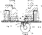
图3是打印头主要部件的放大截面图;Figure 3 is an enlarged cross-sectional view of the main components of the print head;
图4是说明性视图,图解用于确定凸出部高度的条件方程的推导过程;FIG. 4 is an explanatory view illustrating the derivation of a conditional equation for determining the height of a protrusion;
图5是说明性视图,图解清洁辊外形的恢复速度的测量过程;FIG. 5 is an explanatory view illustrating a process of measuring the recovery speed of the cleaning roller profile;
图6是清洁机构结构的截面图;Fig. 6 is a sectional view of the structure of the cleaning mechanism;
图7A和图7B是图解打印头墨盒的清洁操作的说明性视图;7A and 7B are explanatory views illustrating the cleaning operation of the print head cartridge;
图8是说明性视图,图解在打印头墨盒的清洁操作中清洁辊抵达凸出部时的状态;Fig. 8 is an explanatory view illustrating a state when a cleaning roller reaches a protrusion in a cleaning operation of a print head cartridge;
图9是说明性视图,图解在打印头墨盒的清洁操作中清洁辊翻过凸出部时的状态;Fig. 9 is an explanatory view illustrating a state when a cleaning roller rolls over a protrusion in a cleaning operation of the print head cartridge;
图10是按照本发明第二实施例打印头墨盒主要部件的放大截面图;Fig. 10 is an enlarged cross-sectional view of main components of a print head cartridge according to a second embodiment of the present invention;
图11是说明性视图,图解偏心凸轮的顶点高度的确定过程;FIG. 11 is an explanatory view illustrating a process of determining the peak height of the eccentric cam;
图12是说明性视图,显示打印头墨盒的清洁操作并图解清洁辊和喷嘴表面之间最大压力接触的状态;以及Figure 12 is an explanatory view showing the cleaning operation of the print head cartridge and illustrating the state of maximum pressure contact between the cleaning roller and the nozzle surface; and
图13是说明性视图,显示打印头墨盒的清洁操作过程中恢复至普通压力接触时的状态。Fig. 13 is an explanatory view showing the state of returning to normal pressure contact during the cleaning operation of the print head cartridge.
具体实施方式Detailed ways
下面将参照附图具体描述本发明的实施例。图1是按照本发明的一种例证性液体喷射装置——喷墨打印机的透视图。喷墨打印机1包括打印机机身2和打印头墨盒3(参看图2),该打印头墨盒3用来向记录纸喷射墨滴以在其上形成图像。Embodiments of the present invention will be specifically described below with reference to the accompanying drawings. FIG. 1 is a perspective view of an exemplary liquid ejecting device, an ink jet printer, according to the present invention. The
图1中所示的打印机机身2包括用来输送装在记录纸托盘4中、用作打印目标的记录纸的输送机构(图中未显示),以及用来适当控制以在记录纸上形成图像的控制器(图中未显示),两者设置在打印机机身2中。记录纸托盘4可拆卸地设置在处于打印机机身2前部下侧的托盘加载槽5上。托盘加载槽5还用作记录纸的排出槽,这样在打印机机身2中完成图像记录的记录纸就可以在设置于记录纸托盘4上的排纸接收器4a上面排出。打印机机身2还装备有布置在机身前部上侧的显示面板6,它用来显示喷墨打印机1的全部操作。The
在打印机机身2的上部表面,连接有开/关顶盖7。在顶盖7下面,提供有布置在机身2上部用来容纳打印头墨盒3的托座8。在打印机机身2的托座8中,将打印头墨盒3沿箭头Z方向插入并可拆卸地装入其中。打印头墨盒3具有沿着打印机机身2的宽度方向,也即是记录纸的宽度方向,细长延伸的外壳,用来在记录纸上喷射黄Y、品红M、青C和黑K的四色墨水以形成图像。打印头墨盒3包括墨水槽9、打印头10以及打印头罩11。On the upper surface of the
下面,将参照图2至图6描述本发明第一实施例的适用于喷墨打印机的打印头墨盒。Next, a print head cartridge suitable for an ink jet printer according to a first embodiment of the present invention will be described with reference to FIGS. 2 to 6. FIG.
图2是图1中所示打印头墨盒3的局部侧视图。在打印头墨盒3中装载有四个墨水槽9(9y,9m,9c和9k)。墨水槽9是用于储存墨水的液体容器,这样墨水槽9分别装有黄、品红、青和黑的四色墨水。墨水槽9将存储其中的墨水供给打印头10。打印头10是一种将墨水槽9供应的墨水在记录纸的整个宽度进行喷射的整行式(full-line)打印头,并且如图3中所示,它包括喷嘴元件12、打印头芯片13、流动通道板14以及打印头机架15。FIG. 2 is a partial side view of the
在打印头10的底部表面上,布置有包括喷嘴表面12a的喷嘴元件12。喷嘴元件12设置有一行喷墨嘴16,布置上述一行喷墨嘴16使得其纵向对应于记录纸的整体宽度。此外,喷嘴表面12a设置有凸出部17,该凸出部被布置为在使用清洁辊21(下文将提及)清洁喷嘴表面12a期间处于清洁辊21的清洁方向(图3中的箭头A方向)上喷墨嘴16的前面。凸出部17暂时增大清洁辊21的弹性变形,这样清洁辊21利用其弹性变形的恢复产生的吸附力将附着于喷嘴表面12a的墨水吸收。凸出部17可以通过以下方式形成:使用分配器沿着与喷墨嘴16的排列平行的方向上将紫外可固化型树脂涂于喷墨嘴16上,然后使用紫外线辐射喷墨嘴16以完成固化。这样,凸出部17的横截面由于树脂的表面张力大致变为半圆形。凸出部17的高度h被设定为具有足于保持弹性变形的恢复直到清洁辊21经过喷墨嘴16的移位量。On the bottom surface of the
具体地说,凸出部17高度h的设定满足下列关系式(1):Specifically, the setting of the height h of the
h>(Vu/Vr)(L+n/2-/2)…(1),h>(Vu/Vr)(L+n/2-/2)...(1),
其中如图4中所示,将清洁辊21的弹性变形的恢复速度定义为Vu;将清洁辊21的移动速度定义为Vr;从弹性变形的恢复初始点(吸附初始点)P1到喷墨嘴16的喷嘴中心之间的水平距离为L;清洁辊21与喷嘴表面12a之间的接触宽度(夹挤宽度,nip width)为n;而喷墨嘴16的直径为。在这种情况下,n>。凸出部17的高度h大致与清洁辊21由于凸出部17造成的弹性移位量(暂时增大的弹性移位量)相一致,并且等于弹性变形的深度。此外,在比设定凸出部17的高度h;作为选择,可以设定任何其他参数来满足关系式(1)。Wherein as shown in Figure 4, the recovery speed of the elastic deformation of cleaning
下面将具体描述关系式(1)的推导过程。The derivation process of relational expression (1) will be described in detail below.
如上所述,由于凸出部17的高度h大致与清洁辊21由凸出部17施压增大的弹性移位量相一致,清洁辊21由于凸出部17施压发生的弹性变形恢复至初始形状所必需的时间Tu可表达为:As described above, since the height h of the
Tu=h/Vu…(2),Tu=h/Vu...(2),
其中符号Vu表示弹性变形的恢复速度。因为恢复速度Vu是每单位时间的弹性变形恢复量,通过使用与清洁辊21相同性质的切割样品可以容易地获得该数值。也就是说,如图5中所示,在对其宽度等于夹挤宽度n的切割样品30施加压缩变形量H之后,通过测量从压缩解除到恢复至初始形状的时间t,可以获得恢复速度Vu如下:The symbol Vu represents the recovery speed of elastic deformation. Since the recovery speed Vu is the elastic deformation recovery amount per unit time, this value can be easily obtained by using a cut sample of the same nature as the cleaning
Vu=H/t。Vu=H/t.
为了给喷墨嘴16施加清洁辊21恢复期间产生的吸附力,上述清洁辊21由于凸出部17施压而发生变形,在时间Tu内,清洁辊21可以通过喷墨嘴16。由此,清洁辊21从如图4所示的恢复初始点(吸附初始点)移动至经过喷墨嘴的点P2所必需的时间Tr可以满足下列关系式:In order to apply to the
Tu>Tr…(3)。Tu > Tr... (3).
此处的数值Tr可以通过下列关系式获得:The value Tr here can be obtained by the following relationship:
Tr=(L+n/2-/2)/rωTr=(L+n/2-/2)/rω
=(L+n/2-/2)/Vr…(4),=(L+n/2-/2)/Vr...(4),
其中如图4中所示清洁辊21的半径为r而清洁辊21的角速度为ω。相应地,通过将关系式(2)和(4)代换入关系式(3)以重新整理,可推导出关系式(1)。Wherein, as shown in FIG. 4 , the radius of the cleaning
除此之外,如图3中所示在喷嘴元件12的上表面,布置有打印头芯片13。打印头芯片13包括基于图像信号来控制墨水喷射的逻辑电路(图中未显示)以及用于驱动加热电阻18(以下将提及)的晶体管,并相对于喷墨嘴16设置有加热电阻18,以给墨水加压室19中的墨水供应喷射能量,借助加热电阻18产生的热能,墨水被直接供给喷墨嘴16以便从喷墨嘴16喷射墨水。Besides, on the upper surface of the
此外,在打印头芯片13的上表面,布置有流动通道板14以构成将墨水从墨水槽9供给墨水加压室19的墨水流动通道20。尽管在图3中流动通道板14显示为在横向方向上分隔,事实上它们彼此连接具有整体结构。在流动通道板14的两侧,打印头机架15设立于喷嘴元件12上用来支持喷嘴元件12。Furthermore, on the upper surface of the
如图2中所示,在打印头10的底表面可拆卸地设置有打印头罩11。打印头罩11可相对于打印头10移动以便在固定状态时保护打印头10的喷嘴表面12a,此外它包括用于清洁喷嘴表面12a的清洁单元。具体地说,如图6中所示,打印头罩11构成为固体树脂的细长盒子并在四角具有上升件,它包括布置于内部的清洁辊21和刮器22,以及配置在底部表面的墨水接收元件23。As shown in FIG. 2 , a
图2和图6中所示的清洁辊21在移动并压触打印头10的喷嘴表面12a期间用作擦拭墨水渣和灰尘的擦拭元件,此外它包括用于向打印头10的喷嘴表面12a施加去污剂的施加单元。圆柱体的清洁辊21在打印头罩11的纵向上邻近打印头罩11的一侧连接,以使其平行于打印头10喷嘴表面12a的纵向。清洁辊21由包括细孔21a(参看图7B)的弹性多孔材料构成,就像海绵和毡一样用来吸附液体,此外它具有浸渍其中的去污剂溶液。The cleaning
如图2和图6中所示,在接触清洁辊21的一外侧表面的位置上布置有刮器22。刮器22用于将墨水渣和灰尘从清洁辊21的表面刮走。图6中所示的墨水接收元件23由譬如海绵的吸湿性材料构成,以打印头罩11的整个底表面用来接收从打印头10的喷墨嘴16初期(preliminarily)喷射出的墨滴。由此,墨水接收元件23除了能够吸收墨水,还防止了从喷墨嘴16初期喷射出的墨水溅回,从而防止了墨水淤积在打印头底部表面。相应地,也防止了初期喷射墨水由于墨水溅回而重新附着在喷嘴表面12a上。As shown in FIGS. 2 and 6 , a
将如图2中所示方式构成的打印头罩11沿着垂直于喷嘴表面12a纵向的方向,或者沿箭头A和B的方向移动。当打印头罩11沿着箭头A方向移动时,它从打印头10移去,而当沿着箭头B方向返回时,打印头罩11再次固定于打印头10上以便保护喷嘴表面12a。接着,清洁辊21随着打印头罩11的打开(图中沿着箭头A方向移动时)对打印头10的喷嘴表面12a进行清洁。在适当的服务时间之后,已经吸附了初期喷射墨水的墨水接收元件23被新的墨水接收元件23替代,从而可简易地执行对打印头罩11中初期喷射墨水的清洁工作。The head cover 11 constructed as shown in FIG. 2 is moved in a direction perpendicular to the longitudinal direction of the
下面,将参照图7A-9来描述按照本发明第一实施例的打印头墨盒的清洁操作。Next, the cleaning operation of the print head cartridge according to the first embodiment of the present invention will be described with reference to FIGS. 7A-9.
首先,参照图1,将打印头墨盒3沿着箭头Z的方向固定安装于打印机机身2的托座8。然后将记录纸托盘4装在托盘加载槽5中。在这种状况下,在启动打印前,随着打印头罩11的打开对打印头10的喷嘴表面12a进行清洁。该清洁操作执行如下:在图2所示沿着箭头A的方向移动打印头罩11的同时,对清洁辊21施压接触喷嘴表面12a。这时,清洁辊21在如图7A中所示沿着箭头C方向转动的同时沿着箭头A方向移动。由于清洁辊21由多孔材料构成,当如图7B中所示清洁辊21被施压接触喷嘴表面12a时,清洁辊21被施压部分的细孔21a被挤压并尺寸减小,以致在图中所示箭头D方向上产生比其他部分更大的毛细管力Qn。接着,粘附在喷嘴表面12a上的墨水24易于渗透进入细孔21a。由于随着清洁辊21的滚动在施压被解除的部分,同时发生弹性移位的恢复,这样被挤压的细孔21a将恢复至初始形状,从而在该部分沿着箭头E的方向产生吸附力Qr。因此,通过清洁辊21毛细管力Qn与吸附力Qr的总和(Qn+Qr)被施加于喷嘴表面12a以便吸附并去除粘附在喷嘴表面12a上的墨水24。此外,毛细管力Qn与吸附力Qr与在清洁辊21在预定压力下压住喷嘴表面12a的同时发生移动的常规清洁操作过程中、在清洁辊21中产生的吸附源是相同的。First, referring to FIG. 1 , the print
而且,当清洁辊21在图7A中沿着箭头A方向旋转到达布置在如图8中所示箭头A方向上喷墨嘴16前方的凸出部17时,清洁辊21为凸出部17施压,以致清洁辊21的表面弹性凹下。Moreover, when the cleaning
清洁辊21翻过凸出部17并沿着图8中箭头A的方向继续转动。这时,对清洁辊由于凸出部17施压而发生弹性变形的部分,压力解除以便恢复初始形状。通过这种对清洁辊21弹性变形的恢复操作,在清洁辊21中以一种类似水泵操作的方式在图9中箭头F方向上产生向外的吸附力。同时,清洁辊21被施压部分沿着图中箭头G方向也产生差不多相同强度的吸附力Qt。由此,毛细管力Qn、吸附力Qr、以及泵操作吸附力Qt的总和成为吸附力(Qn+Qr+Qt),藉此,该力由于吸附力Qt而增大。The cleaning
由于凸出部17的高度h(或者清洁辊21暂时增大的弹性移位量)的设定满足上述关系式(1),清洁辊21在其从图4中所示恢复初始点(吸附初始点)P1至经过喷墨嘴的点P2的移动过程中连续恢复。这样,当清洁辊21经过喷墨嘴16时,清洁辊21上增大的液体吸附力施加给喷墨嘴16。相应地,附着在喷墨嘴或其周围以致变稠的墨水被吸附并清除。Since the setting of the height h of the protruding portion 17 (or the amount of temporarily increased elastic displacement of the cleaning roller 21) satisfies the above-mentioned relational expression (1), the cleaning
以这样的方式,按照本发明第一实施例的打印头墨盒3,提供了布置于清洁方向上喷墨嘴16前面的凸出部17,这样对凸出部17施压导致的清洁辊21弹性变形的外形恢复操作而产生了吸附力Qt。由此,对于随着清洁辊21转动通常产生的毛细管力Qn和吸附力Qr,还增加了上述的吸附力Qt,这样这种增大的液体吸附力改善了使用清洁辊21的清洁操作。因此,附着在喷墨嘴或其周围以致变稠的墨水被有效地清除。In this way, according to the
通过保证清洁辊21在其经过喷墨嘴16之前一直进行弹性变形的恢复操作,可以对喷墨嘴16施加由于恢复操作增加了吸附力Qt而增大了的吸附力。由此,附着在喷墨嘴或其周围以致变稠的墨水被有效地清除,改善了喷射性能和图像打印质量。By ensuring that the cleaning
按照第一实施例,将圆柱体形的清洁辊21作为例证;作为选择,它可以不是圆柱体形而是棱柱形。在这种情况下,尽管在随着清洁辊21的转动受压状态被解除的部分中产生的吸附力Qr,由于清洁辊21并不滚过喷嘴表面12a而不存在,但随着由凸出部17导致的弹性变形的恢复而产生的吸附力Qt增加给毛细管力Qn,这样增大的液体吸附力也能以圆柱体形清洁辊21相同的方式改善清洁操作。According to the first embodiment, a
图10是按照本发明第二实施例的打印头墨盒主要部分的截面图。如图10中所示,清洁辊21在邻近于打印头罩11的一侧进行安装,所述打印头罩11布置在打印头墨盒3的打印头10的底部表面。清洁辊21与轴接于轴承26上的旋转轴25一体提供,上述轴承26在其纵向上布置在打印头罩11底部表面上。Fig. 10 is a sectional view of a main part of a print head cartridge according to a second embodiment of the present invention. As shown in FIG. 10 , the cleaning
此外,旋转轴25与偏心凸轮27一体提供。图10中所示偏心凸轮27的滑动接触面27b的一半被形成为具有相同的旋转半径,而另外一半朝外突起具有不同的旋转半径。使滑动接触面27b与布置在轴承26中的固定部分28的上表面相接触,这样偏心凸轮27在固定部分28上发生偏心旋转,以致清洁辊21升起以增大清洁辊21处于清洁方向(图10中箭头A的方向)上喷墨嘴16前面位置的弹性位移。清洁辊21的最大升起高度h(参看图11)被确定为:可以施加足够的变形,以便保持弹性变形的恢复的同时清洁辊21经过喷墨嘴16。最大升起高度h与偏心凸轮27的顶点27a的凸出(高度)相一致,并基本与清洁辊21由于偏心凸轮27导致的弹性移位量(暂时增大的弹性移位量)相一致。在这种情况下,如图11中所示,如果将清洁辊21最大升起的点定义为恢复初始点(吸附初始点)P1,而将其他参数如第一实施例中相同定义,上述的等式(1)可以同样适用。相应地,如果清洁辊21的最大升起量h被确定满足等式(1),那么可以保证弹性变形的恢复的同时清洁辊21经过喷墨嘴16。Furthermore, the
此外,如图10中所示,轴承26配置有垂直拉长的椭圆形轴承孔29,这样清洁辊21的旋转轴25可以垂直移动。轴承26还在轴承孔29的顶端配置有切口29a,这样旋转轴25可以通过切口29a拆卸,从而能够替换清洁辊21。Furthermore, as shown in FIG. 10, the bearing 26 is provided with a vertically elongated
下面,将参照图10-13描述按照第二实施例的打印头墨盒的清洁操作。Next, the cleaning operation of the print head cartridge according to the second embodiment will be described with reference to FIGS. 10-13.
在清洁操作期间,如图10中沿着箭头A的方向移动打印头罩11,这时清洁辊21被施压接触打印头10的喷嘴表面12a。在此期间,清洁辊21在沿着如图中箭头C方向转动的同时,沿着图10中箭头A方向移动,这时旋转轴25轴接于布置在打印头罩11中的轴承26上。在清洁操作的第一阶段,与旋转轴25整体提供的偏心凸轮27旋转,并以旋转半径相同的一半滑动接触面27b同轴承26的固定部分28发生接触。相应地,在这个阶段,清洁辊通过保持与喷嘴表面12a预定压力接触量来执行所谓的常规清洁。在这一阶段,如图7B中所示,在清洁辊21与喷嘴表面12a之间的压力接触面上沿着如图中箭头D的方向产生了毛细管力Qn。此外,随着清洁辊21的转动在喷嘴表面12a施压解除的部分沿着箭头E方向产生了吸附力Qr。由此,毛细管力Qn与吸附力Qr的总和(Qn+Qr)被施加于喷嘴表面12a,以便通过清洁辊21吸附并去除粘附在喷嘴表面12a上的墨水24。During the cleaning operation, the
此外,随着清洁辊21的转动,偏心凸轮27也进行旋转。当具有相同旋转半径的一半滑动接触面27b与固定部分28发生接触的状态结束后,偏心凸轮27的旋转半径逐渐增加。与此同时,清洁辊21在如图12箭头I所示方向上逐渐升起以增大与喷嘴表面12a的压力接触量。In addition, as the cleaning
接着,如图12中所示,当偏心凸轮27的顶点27a邻靠固定部分28时,清洁辊21上升至最高(高度h)。由此,清洁辊21与喷嘴表面12a之间的压力接触量达到最大,使得清洁辊21的弹性移位量达到最大。在此状态下,清洁辊21的中心轴与图11中所示恢复初始点(吸附初始点)P1相一致。Next, as shown in FIG. 12, when the apex 27a of the
接着,当打印头罩11从图12的状态沿着箭头A方向移动时,清洁辊21在转动的同时经过喷墨嘴16。同时,伴随着清洁辊21的转动,偏心凸轮27在固定部分28上旋转,使得偏心凸轮27的旋转半径逐渐减小。由此,清洁辊21在如图13箭头J所示方向逐渐下降,使得清洁辊21与喷嘴表面12a之间的压力接触量逐渐减小。随着清洁辊21的转动,偏心凸轮27进一步旋转到达图13的状态,这时压力接触量复原至图10所示的初始状态。Next, when the
以这样的方式,在从图12所示状态转换至图13所示状态的过程中,当压力接触量减小时,压力接触部分的弹性变形发生恢复。在恢复操作的同时,清洁辊21中产生吸附力Qt。而且,由于清洁辊21的最大上升量h(或者偏心凸轮27的顶点27a的高度,或者清洁辊21暂时增大的弹性移位量)被确定为可以继续进行清洁辊21的弹性变形的恢复的同时清洁辊21经过喷墨嘴16,在清洁辊21经过喷墨嘴16期间也保持了弹性变形的恢复操作。因此,随着恢复操作产生的吸附力施加给喷墨嘴16。这样,普通产生的毛细管力Qn、吸附力Qr以及吸附力Qt的总和吸附力(Qn+Qr+Qt)施加给喷墨嘴16及其周围,改善了使用清洁辊21的清洁性能。In this way, during the transition from the state shown in FIG. 12 to the state shown in FIG. 13, when the pressure contact amount is reduced, the elastic deformation of the pressure contact portion is restored. Simultaneously with the recovery operation, an adsorption force Qt is generated in the cleaning
以这样的方式,按照本发明第二实施例的打印头墨盒,在清洁操作过程中压力接触量随着清洁辊21的垂直移动而改变,使得当清洁辊21下降以减小压力接触量时产生吸附力Qt。通过将吸附力Qt增加给随着清洁辊21的转动通常产生的毛细管力Qn和吸附力Qr而增大的吸附力,可以施加给喷墨嘴16。相应地,使用清洁辊21的清洁性能得到改善,由此有效地清除附着在喷嘴表面12a上以致变稠的墨水。In this way, according to the print head cartridge of the second embodiment of the present invention, the amount of pressure contact changes with the vertical movement of the cleaning
而且,通过保持清洁辊21在其经过喷墨嘴16之前发生弹性变形的恢复操作,可以对喷墨嘴16施加由于恢复操作增加了吸附力Qt而增大了的吸附力。相应地,附着在喷墨嘴或其周围以致变稠的墨水被有效地清除,改善了喷射性能和图像打印质量。Also, by keeping the restoring operation of the cleaning
由于喷嘴表面12a上不存在凸出体,喷嘴表面12a难于被墨水附着和沾污。Since there are no projections on the
此外,如果打印头墨盒3用于彩色打印,可以设置偏心凸轮27的四个顶点27a。在这种情况下,将每个顶点27a布置为可以在清洁方向上每个彩色喷墨嘴16前面的位置处最大升起清洁辊21。接着,当清洁辊21经过每个彩色喷墨嘴16时,将每个顶点27a的高度h确定为能满足上述等式(1)并能保证喷墨嘴16弹性变形的恢复操作。In addition, if the
在以上的描述中,将喷墨打印机作为例证;但本发明并不局限与此,而可以运用于任何从喷液嘴喷射如液滴之类的预定液体的设备。举例来说,也可以包括譬如喷墨传真机和喷墨复印机之类的图像形成设备。In the above description, an inkjet printer was exemplified; however, the present invention is not limited thereto, but can be applied to any device that ejects predetermined liquid such as liquid droplets from liquid ejection nozzles. For example, image forming apparatuses such as inkjet facsimile machines and inkjet copiers may also be included.
从喷液嘴喷出的液体并不局限于墨水,而可以包括其他类的液体喷射装置,只要它们通过从喷液头喷射预定液体形成点和点线。举例来说,也可以包括在DNA检测中将包括DNA的液体喷射至选项板的液体喷射装置,以及喷射包括导电粒子的液体来形成印刷电路板布线图的液体喷射装置。The liquid ejected from the liquid ejecting nozzle is not limited to ink but may include other kinds of liquid ejecting devices as long as they form dots and dot lines by ejecting a predetermined liquid from a liquid ejecting head. For example, a liquid ejection device that ejects a liquid including DNA to an option board in DNA detection, and a liquid ejection device that ejects a liquid including conductive particles to form a wiring pattern of a printed circuit board may also be included.
Claims (24)
Applications Claiming Priority (6)
| Application Number | Priority Date | Filing Date | Title |
|---|---|---|---|
| JP2004059433A JP4085991B2 (en) | 2004-03-03 | 2004-03-03 | Head cartridge and liquid ejection device |
| JP059433/2004 | 2004-03-03 | ||
| JP059434/2004 | 2004-03-03 | ||
| JP059433/04 | 2004-03-03 | ||
| JP2004059434A JP4131247B2 (en) | 2004-03-03 | 2004-03-03 | Head cartridge and liquid ejection device |
| JP059434/04 | 2004-03-03 |
Publications (2)
| Publication Number | Publication Date |
|---|---|
| CN1663805A true CN1663805A (en) | 2005-09-07 |
| CN100381289C CN100381289C (en) | 2008-04-16 |
Family
ID=35035187
Family Applications (1)
| Application Number | Title | Priority Date | Filing Date |
|---|---|---|---|
| CNB2005100641976A Expired - Fee Related CN100381289C (en) | 2004-03-03 | 2005-03-03 | Printhead Cartridges and Liquid Ejectors |
Country Status (2)
| Country | Link |
|---|---|
| US (3) | US7334865B2 (en) |
| CN (1) | CN100381289C (en) |
Cited By (4)
| Publication number | Priority date | Publication date | Assignee | Title |
|---|---|---|---|---|
| CN108162593A (en) * | 2013-02-15 | 2018-06-15 | 精工爱普生株式会社 | Recording device |
| CN108909189A (en) * | 2018-07-26 | 2018-11-30 | 深圳怡化电脑股份有限公司 | A kind of printing equipment |
| CN110861300A (en) * | 2019-11-30 | 2020-03-06 | 共享智能铸造产业创新中心有限公司 | High-resolution printing device and printing equipment |
| CN117984667A (en) * | 2022-11-07 | 2024-05-07 | 华为技术有限公司 | printer |
Families Citing this family (11)
| Publication number | Priority date | Publication date | Assignee | Title |
|---|---|---|---|---|
| US7334865B2 (en) * | 2004-03-03 | 2008-02-26 | Sony Corporation | Head cartridge and liquid ejection apparatus |
| US7686419B2 (en) * | 2005-10-11 | 2010-03-30 | Silverbrook Research Pty Ltd | Method of maintaining a printhead using a roller action |
| US7506958B2 (en) * | 2005-10-11 | 2009-03-24 | Silverbrook Research Pty Ltd | Printhead maintenance station |
| US7648222B2 (en) * | 2005-10-11 | 2010-01-19 | Silverbrook Research Pty Ltd | Printhead maintenance station comprising maintenance roller and ink removal system |
| US7695097B2 (en) * | 2005-10-11 | 2010-04-13 | Silverbrook Research Pty Ltd | Printhead maintenance station having roller pad |
| US7753472B2 (en) * | 2005-10-11 | 2010-07-13 | Silverbrook Research Pty Ltd | Printhead maintenance station having rotational pad engagement |
| US8342638B2 (en) * | 2009-11-30 | 2013-01-01 | Hewlett-Packard Development Company, L.P. | Servicing article |
| TWI534015B (en) * | 2010-05-17 | 2016-05-21 | 滿捷特科技公司 | System for reducing ink color mixing effects in printer |
| US20110279521A1 (en) | 2010-05-17 | 2011-11-17 | Silverbrook Research Pty Ltd | Apparatus for assisting printing having offset wick |
| JP6044307B2 (en) | 2012-12-04 | 2016-12-14 | セイコーエプソン株式会社 | Liquid ejector |
| US10581470B2 (en) | 2017-06-09 | 2020-03-03 | Nanosemi, Inc. | Linearization system |
Family Cites Families (12)
| Publication number | Priority date | Publication date | Assignee | Title |
|---|---|---|---|---|
| JP3319474B2 (en) | 1993-03-03 | 2002-09-03 | セイコーエプソン株式会社 | Cleaning device for inkjet head |
| JPH0732611A (en) * | 1993-07-22 | 1995-02-03 | Canon Inc | Inkjet recording device |
| JPH08207293A (en) * | 1995-02-08 | 1996-08-13 | Funai Electric Co Ltd | Printing head cleaning device in printer |
| JPH1044447A (en) | 1996-08-08 | 1998-02-17 | Minolta Co Ltd | Maintenance apparatus of ink jet head |
| JPH10323988A (en) * | 1997-03-25 | 1998-12-08 | Seiko Epson Corp | Ink jet recording device |
| US6460967B1 (en) * | 1998-03-24 | 2002-10-08 | Konica Corporation | Liquid jetting apparatus |
| US6652062B2 (en) * | 2000-03-31 | 2003-11-25 | Canon Kabushiki Kaisha | Liquid discharge recording head with orifice plate having extended portion fixed to recording head main body, liquid discharge recording apparatus having such head, and method for manufacturing such head |
| JP4945843B2 (en) * | 2001-02-21 | 2012-06-06 | ソニー株式会社 | Inkjet head and inkjet printer |
| US6869163B2 (en) * | 2002-05-21 | 2005-03-22 | Brother Kogyo Kabushiki Kaisha | Ink-jet recording apparatus |
| JP4389443B2 (en) * | 2002-12-20 | 2009-12-24 | セイコーエプソン株式会社 | Wiping unit for inkjet head, liquid droplet ejection apparatus including the same, and method for manufacturing electro-optical device |
| JP2005022193A (en) * | 2003-07-01 | 2005-01-27 | Canon Inc | Inkjet recording device |
| US7334865B2 (en) * | 2004-03-03 | 2008-02-26 | Sony Corporation | Head cartridge and liquid ejection apparatus |
-
2005
- 2005-03-01 US US11/069,376 patent/US7334865B2/en not_active Expired - Fee Related
- 2005-03-03 CN CNB2005100641976A patent/CN100381289C/en not_active Expired - Fee Related
-
2007
- 2007-07-05 US US11/773,635 patent/US7735960B2/en not_active Expired - Fee Related
- 2007-11-27 US US11/945,741 patent/US8201920B2/en not_active Expired - Fee Related
Cited By (4)
| Publication number | Priority date | Publication date | Assignee | Title |
|---|---|---|---|---|
| CN108162593A (en) * | 2013-02-15 | 2018-06-15 | 精工爱普生株式会社 | Recording device |
| CN108909189A (en) * | 2018-07-26 | 2018-11-30 | 深圳怡化电脑股份有限公司 | A kind of printing equipment |
| CN110861300A (en) * | 2019-11-30 | 2020-03-06 | 共享智能铸造产业创新中心有限公司 | High-resolution printing device and printing equipment |
| CN117984667A (en) * | 2022-11-07 | 2024-05-07 | 华为技术有限公司 | printer |
Also Published As
| Publication number | Publication date |
|---|---|
| US20070247487A1 (en) | 2007-10-25 |
| US8201920B2 (en) | 2012-06-19 |
| US20080074463A1 (en) | 2008-03-27 |
| US7334865B2 (en) | 2008-02-26 |
| US7735960B2 (en) | 2010-06-15 |
| US20050219310A1 (en) | 2005-10-06 |
| CN100381289C (en) | 2008-04-16 |
Similar Documents
| Publication | Publication Date | Title |
|---|---|---|
| US8201920B2 (en) | Head cartridge and liquid ejection apparatus | |
| JP4366175B2 (en) | Inkjet recording device | |
| JP4872849B2 (en) | Fluid ejection device | |
| CN100335277C (en) | Ink-jet recording apparatus | |
| CN1496839A (en) | Inkjet recording device and maintenance method of inkjet head provided in inkjet recording device | |
| EP3231613B1 (en) | Cleaning device of liquid ejection head and liquid ejection device | |
| JP7105163B2 (en) | Inkjet printer and wiping method | |
| CN100551703C (en) | Inkjet image forming apparatus with capping unit | |
| KR20090128243A (en) | Nozzle Wetting Device and Inkjet Image Forming Device Having the Same | |
| JP2005199597A (en) | Liquid ejector | |
| CN1676337A (en) | Wiper assembly for liquid jetting equipment | |
| JP2010194923A (en) | Image forming apparatus | |
| JP2004106280A (en) | Ink jet printer | |
| JP2005153183A (en) | Cleaning blade for liquid discharge device, cleaning mechanism having cleaning blade, liquid discharge cartridge, and liquid discharge device | |
| JP2005313412A (en) | Discharge port surface cleaning method, liquid discharge apparatus, and probe carrier manufacturing apparatus | |
| JP2006247999A (en) | Liquid ejecting apparatus and wiping method in liquid ejecting apparatus | |
| JP2010058473A (en) | Head cleaning device and image forming apparatus using the same | |
| JP5262365B2 (en) | Liquid discharge recording apparatus and ink jet recording apparatus | |
| JP4131247B2 (en) | Head cartridge and liquid ejection device | |
| CN1774342A (en) | Head cleaning member for ink jet printer | |
| CN1939727A (en) | Image forming apparatus comprising hybrid inkjet head and inkjet head wiping device | |
| JPH0924625A (en) | Ink jet recording device | |
| JP2007130807A (en) | Inkjet recording device | |
| JP2005342991A (en) | Liquid ejecting apparatus and liquid absorbing apparatus for liquid ejecting head | |
| JP4085991B2 (en) | Head cartridge and liquid ejection device |
Legal Events
| Date | Code | Title | Description |
|---|---|---|---|
| C06 | Publication | ||
| PB01 | Publication | ||
| C10 | Entry into substantive examination | ||
| SE01 | Entry into force of request for substantive examination | ||
| C14 | Grant of patent or utility model | ||
| GR01 | Patent grant | ||
| C17 | Cessation of patent right | ||
| CF01 | Termination of patent right due to non-payment of annual fee |
Granted publication date: 20080416 Termination date: 20130303 |