CN1663193B - Method for managing link resources in a communication network - Google Patents
Method for managing link resources in a communication network Download PDFInfo
- Publication number
- CN1663193B CN1663193B CN028107578A CN02810757A CN1663193B CN 1663193 B CN1663193 B CN 1663193B CN 028107578 A CN028107578 A CN 028107578A CN 02810757 A CN02810757 A CN 02810757A CN 1663193 B CN1663193 B CN 1663193B
- Authority
- CN
- China
- Prior art keywords
- link
- channel
- bandwidth
- available
- register
- Prior art date
- Legal status (The legal status is an assumption and is not a legal conclusion. Google has not performed a legal analysis and makes no representation as to the accuracy of the status listed.)
- Expired - Fee Related
Links
Images


Classifications
-
- H—ELECTRICITY
- H04—ELECTRIC COMMUNICATION TECHNIQUE
- H04L—TRANSMISSION OF DIGITAL INFORMATION, e.g. TELEGRAPHIC COMMUNICATION
- H04L12/00—Data switching networks
- H04L12/28—Data switching networks characterised by path configuration, e.g. LAN [Local Area Networks] or WAN [Wide Area Networks]
- H04L12/40—Bus networks
-
- H—ELECTRICITY
- H04—ELECTRIC COMMUNICATION TECHNIQUE
- H04L—TRANSMISSION OF DIGITAL INFORMATION, e.g. TELEGRAPHIC COMMUNICATION
- H04L47/00—Traffic control in data switching networks
- H04L47/70—Admission control; Resource allocation
- H04L47/82—Miscellaneous aspects
- H04L47/824—Applicable to portable or mobile terminals
-
- H—ELECTRICITY
- H04—ELECTRIC COMMUNICATION TECHNIQUE
- H04L—TRANSMISSION OF DIGITAL INFORMATION, e.g. TELEGRAPHIC COMMUNICATION
- H04L12/00—Data switching networks
- H04L12/28—Data switching networks characterised by path configuration, e.g. LAN [Local Area Networks] or WAN [Wide Area Networks]
- H04L12/46—Interconnection of networks
- H04L12/4604—LAN interconnection over a backbone network, e.g. Internet, Frame Relay
-
- H—ELECTRICITY
- H04—ELECTRIC COMMUNICATION TECHNIQUE
- H04L—TRANSMISSION OF DIGITAL INFORMATION, e.g. TELEGRAPHIC COMMUNICATION
- H04L47/00—Traffic control in data switching networks
- H04L47/70—Admission control; Resource allocation
-
- H—ELECTRICITY
- H04—ELECTRIC COMMUNICATION TECHNIQUE
- H04L—TRANSMISSION OF DIGITAL INFORMATION, e.g. TELEGRAPHIC COMMUNICATION
- H04L47/00—Traffic control in data switching networks
- H04L47/70—Admission control; Resource allocation
- H04L47/72—Admission control; Resource allocation using reservation actions during connection setup
- H04L47/724—Admission control; Resource allocation using reservation actions during connection setup at intermediate nodes, e.g. resource reservation protocol [RSVP]
-
- H—ELECTRICITY
- H04—ELECTRIC COMMUNICATION TECHNIQUE
- H04L—TRANSMISSION OF DIGITAL INFORMATION, e.g. TELEGRAPHIC COMMUNICATION
- H04L47/00—Traffic control in data switching networks
- H04L47/70—Admission control; Resource allocation
- H04L47/80—Actions related to the user profile or the type of traffic
- H04L47/803—Application aware
-
- H—ELECTRICITY
- H04—ELECTRIC COMMUNICATION TECHNIQUE
- H04L—TRANSMISSION OF DIGITAL INFORMATION, e.g. TELEGRAPHIC COMMUNICATION
- H04L47/00—Traffic control in data switching networks
- H04L47/70—Admission control; Resource allocation
- H04L47/82—Miscellaneous aspects
- H04L47/822—Collecting or measuring resource availability data
Landscapes
- Engineering & Computer Science (AREA)
- Computer Networks & Wireless Communication (AREA)
- Signal Processing (AREA)
- Data Exchanges In Wide-Area Networks (AREA)
- Small-Scale Networks (AREA)
- Mobile Radio Communication Systems (AREA)
- Communication Control (AREA)
Abstract
Description
技术领域technical field
本发明涉及一种用于管理通信网络中的链路资源的方法,该链路可以是无线链路,特别地该网络包括了在无线链路帮助下互连的有线通信总线。The invention relates to a method for managing link resources in a communication network, which may be wireless links, in particular the network comprising wired communication buses interconnected with the help of wireless links.
背景技术Background technique
在包括多个互连的传输媒介的网络中,各个传输媒介的可用带宽没有必要相同。In a network comprising multiple interconnected transmission media, the available bandwidth of each transmission medium need not be the same.
例如,如果考虑到由5GHz ETSI BRAN HiperLAN 2无线链路连接在一起的两个IEEE1394有线串行总线,每个有线总线的可用带宽可以是100Mb/s或更大,而无线链路上的可用带宽可能被限制在30Mb/s之内。因此,对于使用这种链路的连接而言,无线链路造成了瓶颈。For example, if two IEEE1394 wired serial buses connected together by a 5GHz ETSI BRAN HiperLAN 2 wireless link are considered, the available bandwidth on each wired bus can be 100Mb/s or more, while the available bandwidth on the wireless link May be limited to 30Mb/s. Thus, the wireless link creates a bottleneck for connections using such links.
图1为这种网络的一种示例图。该网络包括两条总线11和12,分别将源设备13与宿设备14以及宿设备15与源设备16连接起来。例如源设备13可以是数字VCR,宿设备14和15为显示器而源设备16为调谐器。总线11还与入口17相连接,而总线12与入口18相连,这两个入口形成了总线11和12之间的无线链路。假设在IEEE 1394层,该无线链路对于设备13和16是透明的,即就是说这些设备认为它们处于同一物理总线上。Figure 1 is an example diagram of such a network. The network includes two buses 11 and 12, respectively connecting the source device 13 with the sink device 14 and the sink device 15 with the source device 16. For example, source device 13 may be a digital VCR, sink devices 14 and 15 are displays and source device 16 is a tuner. Bus 11 is also connected to
假设无线链路上可用带宽为30Mb/s,在VCR13与显示器15之间建立20Mb/s的第一连接。由于链路对设备16和14来说是透明的,可以在调谐器16与显示器14之间建立第二连接,但如果第二连接所需要的带宽大于剩余的无线带宽,不管大多少,显示器14也不能显示正确的图像。至于涉及到的创建第二连接的应用,在IEEE1394层仍然可以毫无意外地建立连接,这是因为该层中链路的透明性。Assuming that the available bandwidth on the wireless link is 30 Mb/s, a first connection of 20 Mb/s is established between the VCR 13 and the display 15 . Since the link is transparent to devices 16 and 14, a second connection can be established between tuner 16 and display 14, but if the bandwidth required for the second connection is greater than the remaining wireless bandwidth, no matter how much, display 14 Also does not display the correct image. As far as the application involved in creating the second connection, the connection can still be established without accidents at the IEEE1394 layer because of the transparency of the link in this layer.
参考文件EP-A-0933900公开了一种通过1394桥来互联1394总线的方法。在该文献中,每条总线和桥都由独立的总线构成,并且该方法允许来自不同总线的两个节点进行带宽和信道的预约,从而允许这两个节点之间的同步通信。该方法能在每条独立的总线上进行三个相应的带宽预约,一个用于发送节点,一个用于桥,一个用于接收节点。Reference EP-A-0933900 discloses a method of interconnecting 1394 buses via 1394 bridges. In this document, each bus and bridge is constituted by an independent bus, and the method allows two nodes from different buses to make bandwidth and channel reservations, thus allowing synchronous communication between these two nodes. The method enables three corresponding bandwidth reservations on each independent bus, one for the sending node, one for the bridge, and one for the receiving node.
与上述的文献相反,在本发明中,连接总线的链路是透明的。这就是说,一条总线上的节点能够看见互联的总线上的所有节点,如同属于同一个网络一样。In contrast to the above-mentioned documents, in the present invention the links connecting the buses are transparent. That is, nodes on one bus can see all nodes on interconnected buses as if they belonged to the same network.
发明内容Contents of the invention
本发明的目的是一种用于管理包括至少两条总线的通信网络中的链路资源的方法,所述总线由该链路连接而成一个网络,其中该网络关于由总线使用的协议构成了单一虚拟总线,所述方法包括以下步骤:The object of the present invention is a method for managing link resources in a communication network comprising at least two buses connected by the links to form a network, wherein the network constitutes a network with regard to the protocols used by the buses A single virtual bus, the method comprising the steps of:
在网络的节点中提供一个认识链路(link-aware)的应用,以获得链路资源预约信息;Provide a link-aware application in the nodes of the network to obtain link resource reservation information;
访问所述的信息,以在该链路上的设备之间建立连接;以及access said information to establish a connection between devices on that link; and
作为该信息的函数,确定该连接是否可以被建立。As a function of this information, it is determined whether the connection can be established.
根据实施例,每个链路包括了多个入口,链路的至少一个入口包括了有关其链路的所述资源信息.According to an embodiment, each link includes a plurality of entries, and at least one entry of the link includes the resource information about its link.
根据实施例,信息包括链路上的可用带宽。该信息还包括链路上的可用信道。According to an embodiment, the information includes available bandwidth on the link. This information also includes available channels on the link.
根据实施例,一个应用(application)通过包括以下步骤的方法在网络的两个节点之间建立连接:According to an embodiment, an application establishes a connection between two nodes of the network by a method comprising the following steps:
a在总线上预约(reserving)用于连接的信道和带宽;a reserving (reserving) channels and bandwidth for connection on the bus;
b识别要被连接的节点之间通路上的链路;b identifying the links on the path between the nodes to be connected;
c如果步骤a成功,为所述通路上的每一个链路预约资源。c If step a is successful, reserve resources for each link on the path.
根据实施例,为每一个链路预约资源的步骤包括步骤:According to an embodiment, the step of reserving resources for each link includes the steps of:
-使该应用请求预约与在步骤a从各个链路预约的带宽和信道相同的带宽和信道。- Make the application request to reserve the same bandwidth and channels as reserved in step a from the respective links.
根据实施例,为每一个链路预约资源的步骤进一步包括步骤:According to an embodiment, the step of reserving resources for each link further includes the steps of:
-该应用将要被连接节点的标识符发送到资源要被预约链路的入口;- the application sends the identifier of the node to be connected to the entry of the resource to be reserved link;
-作为被连接节点的功能,使链路判断请求的带宽是否可用;- as a function of the connected node, enabling the link to determine whether the requested bandwidth is available;
-作为此判断的功能,接受或拒绝带宽预约请求。- As a function of this decision, the bandwidth reservation request is accepted or rejected.
根据实施例,为每一个链路预约资源的步骤进一步包括步骤:According to an embodiment, the step of reserving resources for each link further includes the steps of:
-使链路检查被请求的信道的可用性,如果该链路上的信道是可用的,接受信道预约;- cause the link to check the availability of the requested channel and accept the channel reservation if the channel on the link is available;
-检查是否已经达到了链路上被预约信道最大值并且在肯定情况下,拒绝其他的预约。- Check if the maximum number of reserved channels on the link has been reached and if yes, reject further reservations.
根据实施例,对于提供一个表示网络的信道可用性的寄存器和一个表示各个链路的信道可用性的寄存器的步骤,其中上述两个寄存器都包括相同的信道数和各个链路可以并行预约的信道数的最大值,所述最大值小于或等于寄存器中的信道数,在接受了信道预约之后,为链路提供资源信息的入口检查已经被并行预约的信道是否达到了最大值,并在肯定的情况下修改链路的寄存器以表示对于该链路而言没有可用的信道。According to an embodiment, for the step of providing a register indicating the channel availability of the network and a register indicating the channel availability of each link, wherein both of the above two registers include the same number of channels and the number of channels that each link can reserve in parallel maximum value, said maximum value being less than or equal to the number of channels in the register, after accepting the channel reservation, the entry providing resource information for the link checks whether the channels that have been reserved in parallel have reached the maximum value, and in the affirmative The link's register is modified to indicate that there are no channels available for the link.
附图说明Description of drawings
在附图的帮助下,在对无限制实施例的说明中会公开本发明其他的特性及优势,在附图中:Further characteristics and advantages of the invention will be disclosed in the description of non-limiting embodiments with the help of the accompanying drawings in which:
-已说明过的图1所示为包括了无线链路的网络框图,并显示了由该链路构成的带宽瓶颈;- Figure 1, already described, shows a block diagram of a network including a wireless link and shows the bandwidth bottleneck formed by this link;
-图2为根据本发明实施例的网络框图,该网络包括无线链路并显示了在构成无线链路的入口设备中的软件栈和实现本发明用到的寄存器;- Figure 2 is a block diagram of a network according to an embodiment of the invention, the network comprising wireless links and showing the software stacks in the ingress devices constituting the wireless links and the registers used to implement the invention;
-图3所示为预约信道方法的流程图,该方法利用了指出无线链路上可用信道的寄存器;- Figure 3 shows a flow chart of a method for reserving a channel using a register indicating available channels on a wireless link;
-图4所示为释放被预约的信道方法的流程图;- Fig. 4 shows the flowchart of releasing the reserved channel method;
-图5所示为根据本发明不同实施例的链路上带宽的使用和预约的框图;- Fig. 5 shows a block diagram of usage and reservation of bandwidth on a link according to different embodiments of the invention;
-图6所示为释放图5所示带宽的框图;- Figure 6 shows a block diagram for releasing the bandwidth shown in Figure 5;
-图7所示为根据本发明不同实施例,在不同类型网络之间共享的多入口链路的框图;- Figure 7 shows a block diagram of a multi-entry link shared between different types of networks according to different embodiments of the present invention;
-图8所示为图1中网络的框图,这里为了减少无线链路的使用,调整了节点与总线连接。- Fig. 8 shows a block diagram of the network in Fig. 1, where nodes and bus connections are adjusted in order to reduce the use of wireless links.
具体实施方式Detailed ways
尽管本实施例是基于使用ETSI BRAN HiperLAN 2无线链路,也可以使用其他技术,例如执行Internet协议(IP)的链路。此外,尽管在下面说明的实施例中,有线总线之间的链路是无线的,但没有必要必须如此。Although the present embodiment is based on the use of ETSI BRAN HiperLAN 2 wireless links, other technologies such as links implementing the Internet Protocol (IP) can also be used. Furthermore, although in the embodiments described below the links between wired buses are wireless, this need not be the case.
有关IEEE1394的信息可参看由IEEE公布的IEEE文件1394-1995及IEEE 1394a-2000。Information about IEEE1394 can be found in IEEE documents 1394-1995 and IEEE 1394a-2000 published by IEEE.
1、基本信息1. Basic information
为了简化说明,将在附图的帮助下介绍本实施例,这些附图给出了通常各包括两个入口的链路。不过,本发明也可以应用于包括两个以上入口的链路。In order to simplify the description, this embodiment will be described with the help of figures showing links generally comprising two entries each. However, the invention can also be applied to links comprising more than two entries.
图2所示的网络由两个IEEE1394总线(也称为设备群集)21和22形成,每个总线各包括有线IEEE1394总线、多个设备(分别为节点23、24、29以及25、26、30)以及通往无线Hiperlan 2链路的入口。所有节点均为IEEE1394设备。应用可以认识到无线链路的存在和位置。The network shown in Figure 2 is formed by two IEEE1394 buses (also referred to as device clusters) 21 and 22, each bus comprising a wired IEEE1394 bus, a plurality of devices (respectively nodes 23, 24, 29 and 25, 26, 30 ) and the entrance to the wireless Hiperlan 2 link. All nodes are IEEE1394 devices. Applications can be aware of the existence and location of wireless links.
根据本实施例,入口27和28对其他设备来说不是透明的,也可以认为这两个入口是其各自总线上的节点,即,在总线复位之后其性质为物理标识符。然而在IEEE1394层的层面上,链路是透明的:认为所有的节点均位于单一总线上并因此在复位之后的性质为物理标识符。当执行总线复位时,入口27和28发出自身的识别分组,以表示其各自群集上的节点。According to the present embodiment, entries 27 and 28 are not transparent to other devices, and these two entries can also be considered as nodes on their respective buses, ie their nature is physical identifier after bus reset. At the level of the IEEE1394 layer however, the link is transparent: all nodes are considered to be on a single bus and therefore the property after reset is a physical identifier. When a bus reset is performed, portals 27 and 28 send out their own identification packets to identify nodes on their respective clusters.
各个节点都包括IEEE1394软件栈,即就是物理层、链路层、事务层以及应用层。每一个入口在其有线总线接口中也包括这些层。最后,这些入口利用Hiperlan 2协议栈进行通信。Each node includes IEEE1394 software stack, that is, physical layer, link layer, transaction layer and application layer. Each portal also includes these layers in its wired bus interface. Finally, these portals communicate using the
2、链路资源管理器与相关联的寄存器2. Link resource manager and associated registers
根据本发明,入口使与无线链路相关的资源预约信息对于不同群集中节点的应用是可用的。根据本实施例,该信息包括链路上的可用带宽和信道。该信息保留在无线链路的至少一个入口的“无线资源寄存器”中,并可以由应用或不同总线上节点的中间件(middleware)访问到。According to the invention, the portal makes resource reservation information related to radio links available to applications of nodes in different clusters. According to this embodiment, this information includes available bandwidth and channels on the link. This information is kept in a "radio resource register" of at least one entry of the radio link and can be accessed by applications or middleware of nodes on different buses.
众所周知如IEEE1394 1995标准定义的IEEE1394总线包括了所谓的同步资源管理器(或’IRM’),该管理器保留了两个寄存器,‘BANDWITH_AVALABLE’和‘CHANNELS_AVALABLE’,分别指出了总线上的可用带宽和在最多64个同步信道中的可用信道。The well-known IEEE1394 bus as defined by the IEEE1394 1995 standard includes the so-called Isochronous Resource Manager (or 'IRM'), which reserves two registers, 'BANDWITH_AVALABLE' and 'CHANNELS_AVALABLE', which indicate the available bandwidth and Available channels among up to 64 simultaneous channels.
由于根据本实施例涉及IEEE1394层的无线链路是透明的,所以网络中存在单一的IRM。Since the wireless link involving the IEEE1394 layer is transparent according to the present embodiment, a single IRM exists in the network.
与上述标准所定义的相同,表1给出IRM BANDWITH_AVALABLE寄存器的格式:As defined by the above standard, Table 1 gives the format of the IRM BANDWITH_AVALABLE register:

表1Table 1
bw_remaining的初始值等于0X1333个(在10进制系统中为4915)带宽单元.当每次节点的应用期望预约有线总线上的带宽时,应用会检查此值并且如果有足够可用带宽时,减去所需的带宽.否则不能建立连接.The initial value of bw_remaining is equal to 0X1333 (4915 in decimal system) bandwidth units. When the application of each node expects to reserve bandwidth on the wired bus, the application will check this value and if there is enough available bandwidth, subtract The required bandwidth. Otherwise the connection cannot be established.
与上述标准所定义的相同,表2给出了IRM CHANNELS_AVALABLE寄存器的格式:As defined by the above standard, Table 2 shows the format of the IRM CHANNELS_AVALABLE register:
表2Table 2
该寄存器的初始值为0XFFFFFFFF。每一位表示了特定信道的可用性。′channels_available_hi′的最低可用位表示信道0的可用性,而′channels_available_lo′的最高可用位表示信道63的可用性。当每次应用期望预约信道时,应用会检查该寄存器,选择可用信道并将寄存器的对应位置为′0′。当没有足够多的可用信道时,不能建立连接。The initial value of this register is 0XFFFFFFFF. Each bit indicates the availability of a particular channel. The least available bit of 'channels_available_hi' indicates the availability of
为了预约带宽或信道,首先由应用通过读取请求消息读取寄存器。应用接收包含了该寄存器内容的读取响应消息。在检查完被请求资源的可用性之后,应用锁定对应的寄存器的访问权并写入适当的新值。锁定和写入操作由应用发送锁定请求以及IRM发送锁定响应来完成。根据IEEE1394 1995,分开进行对各个寄存器的访问。根据IEEE1394 2000,万一有锁定请求不利冲突,由于锁定响应发回了实际值,则没有必要进行读取。To reserve a bandwidth or channel, the register is first read by the application via a read request message. The application receives a read response message containing the contents of this register. After checking the availability of the requested resource, the application locks access to the corresponding register and writes the appropriate new value. Locking and writing operations are done by the application sending a lock request and the IRM sending a lock response. According to IEEE1394 1995, access to each register is performed separately. According to IEEE1394 2000, in the event of an unfavorable conflict with a lock request, no read is necessary since the lock response sends back the actual value.
根据本实施例,资源管理器在链路层实现。以下论述中这种资源管理器被称为“链路资源管理器”或LRM,以区别于IEEE1394 1995定义的IRM。According to this embodiment, the resource manager is implemented at the link layer. This resource manager is referred to as a "Link Resource Manager" or LRM in the following discussion to distinguish it from the IRM defined in IEEE1394 1995.
根据本实施例,LRM在无线链路的一个入口执行。它管理的两个寄存器,LINK_BANDWIDTH_AVAILABLE和LINK_CHANNEL_AVAILABLE分别表示了无线链路上的可用带宽和可用信道(除了其他信息之外)。According to this embodiment, LRM is performed at one ingress of the wireless link. The two registers it manages, LINK_BANDWIDTH_AVAILABLE and LINK_CHANNEL_AVAILABLE represent the available bandwidth and available channels on the wireless link (among other information), respectively.
表3给出了根据本实施例的LRM LINK_BANDWIDTH_AVAILABLE寄存器的格式:Table 3 provides the format of the LRM LINK_BANDWIDTH_AVAILABLE register according to the present embodiment:

表3table 3
LRM_bw_remaining字段和IRM BANDWITH_AVALABLE寄存器中bw_remaining字段的作用相同。假设链路上的可用带宽与有线总线上的可用带宽不同,则该参数的初始值也不同。如果链路上的可用带宽较低,这个字段的初始值也就较低,而如果链路上的可用带宽较高,由于限制因子是与无线链路相连接的总线上的带宽,所以当进行预约时,该参数永远也不会到0。The LRM_bw_remaining field has the same function as the bw_remaining field in the IRM BANDWITH_AVALABLE register. Assuming that the bandwidth available on the link is different from the bandwidth available on the wired bus, the initial value of this parameter is also different. If the available bandwidth on the link is low, the initial value of this field is also low, and if the available bandwidth on the link is high, since the limiting factor is the bandwidth on the bus connected to the wireless link, when performing When making a reservation, this parameter will never reach 0.
Source_PhyID字段包含了源设备的物理标识符。Sink_PhyID字段包含了宿设备的物理标识符。这些字段的内容由进行预约的应用来定义(利用锁定请求消息),目的是形成讲话者节点(源)与收听者节点(宿)的身份LRM。通过这些标识符,LRM可以判断与LRM_BANDWIDTH_AVAILABLE寄存器的′link_bw_remaining′字段所指出的带宽不相同的实际可用带宽,这将在下文中进行解释。The Source_PhyID field contains the physical identifier of the source device. The Sink_PhyID field contains the physical identifier of the sink device. The contents of these fields are defined by the subscribing application (using the Lock Request message) in order to form the identity LRM of the talker node (source) and listener node (sink). Through these identifiers, the LRM can determine the actual available bandwidth that is different from the bandwidth indicated by the 'link_bw_remaining' field of the LRM_BANDWIDTH_AVAILABLE register, which will be explained below.
根据不同的实施例,请求的Source_PhyID和Sink_PhyID字段包含了要被预约的连接之间入口的物理标识符。According to various embodiments, the Source_PhyID and Sink_PhyID fields of the request contain the physical identifier of the entry between connections to be reserved.
在入口多于两个的无线链路中,任意两个入口之间的可用带宽可能是不同的,例如是入口间传送质量的函数.为了指出这些入口对之间的实际带宽,LRM必须知道哪两个入口是连接的一部分.LRM可以从讲话者和收听者的身份推断出入口.在特定情况下,′link_bw_remaining′字段指出的带宽就不能反映任意两个入口间的实际可用带宽.In a wireless link with more than two entries, the available bandwidth between any two entries may be different, for example, as a function of the quality of transmission between the entries. In order to indicate the actual bandwidth between these entry pairs, the LRM must know which Two entries are part of a link. The LRM can infer the entries from the speaker and listener identities. In certain cases, the bandwidth indicated by the 'link_bw_remaining' field may not reflect the actual available bandwidth between any two entries.
根据本实施例,′link_bw_remaining′字段指出了无线链路的任意两对入口之间的最大可用带宽。如果其请求的数量大于′link_bw_remaining′字段指出的数量,则应用可以立即判断出不可能预约带宽。在其他所有情况下,LRM首先计算涉及到预约的两个端口间的可用带宽并最后在锁定响应中接受或拒绝预约,并在响应的′link_bw_remaining′字段给出源和宿之间的真实可用带宽。According to this embodiment, the 'link_bw_remaining' field indicates the maximum available bandwidth between any two pairs of entries of the wireless link. If the number it requests is greater than the number indicated by the 'link_bw_remaining' field, the application can immediately judge that it is impossible to reserve bandwidth. In all other cases, the LRM first calculates the available bandwidth between the two ports involved in the reservation and finally accepts or rejects the reservation in the lock response, giving the real available bandwidth between source and sink in the 'link_bw_remaining' field of the response .
根据一个变化实施例,′link_bw_remaining′字段包含假值(dummyvalue),此值大于任意应用可能请求的带宽。在这种情况下,由于应用不能从其读取请求中推断出任何的无效带宽信息,所以LRM始终会拒绝带宽预约。According to a variant embodiment, the 'link_bw_remaining' field contains a dummy value greater than the bandwidth that any application may request. In this case, the LRM will always reject the bandwidth reservation since the application cannot infer any invalid bandwidth information from its read request.
在将无线链路严格限制为两个入口的情况下,链路上的可用带宽不是源和宿设备的函数。根据不同的实施例,在包括了这种链路的网络中,不需要LRM BANDWITH_AVALABLE寄存器的前两个字段。不过,还有可能在无线链路上的两个入口使用这些字段。In cases where the wireless link is strictly limited to two ingresses, the available bandwidth on the link is not a function of the source and sink devices. According to various embodiments, in networks that include such links, the first two fields of the LRM BANDWITH_AVALABLE register are not required. However, it is also possible to use these fields on both entries on the radio link.
‘Channel’字段包括由应用进行预约所请求的信道数目。此数目与分配给IRM的CHANNEL_AVAILABLE寄存器的数目相同,就像后面会看到的,这是因为应用在向无线链路的LRM进行预约之前,首先要向IEEE1394网络的IRM进行预约。为了访问LRMLINK_BANDWIDTH_AVAILABLE,通过锁定请求将该字段的内容提供给LRM。The 'Channel' field includes the channel number requested by the application for reservation. This number is the same as the number of CHANNEL_AVAILABLE registers allocated to the IRM, as will be seen later, because the application must first make a reservation with the IRM of the IEEE1394 network before making a reservation with the LRM of the radio link. To access LRMLINK_BANDWIDTH_AVAILABLE, the contents of this field are provided to the LRM via a lock request.
‘f’字段包括用于指示链路上被请求信道的可用性的标记。该字段用于锁定响应,以指示被请求的信道是可用(‘0’)还是无效(‘1’)。这由LRM设置。The 'f' field includes a flag indicating the availability of the requested channel on the link. This field is used in lock responses to indicate whether the requested channel is available ('0') or invalid ('1'). This is set by the LRM.
表4定义了LRM LINK_CHANNELS_AVAILABLE寄存器的格式。此格式与IRM CHANNELS_AVAILABLE寄存器的格式相同,尽管二者功能并不同。Table 4 defines the format of the LRM LINK_CHANNELS_AVAILABLE register. This format is the same as that of the IRM CHANNELS_AVAILABLE register, although the function is different.
表4Table 4
该寄存器的内容与IRM的CHANNELS_AVAILABLE寄存器的内容有着相同的意义。The contents of this register have the same meaning as the contents of the CHANNELS_AVAILABLE register of the IRM.
无线链路允许的信道最大值可能会小于或大于IEEE1394总线64个信道的界限。尽管链路容许比IEEE1394信道数更多的信道数目,但只能使用64,这是由于IEEE1394网络的IRM仅限于这个数字。The maximum channel allowed by the wireless link may be smaller or larger than the limit of 64 channels of the IEEE1394 bus. Although the link allows a greater number of channels than IEEE1394, only 64 can be used because the IRM of the IEEE1394 network is limited to this number.
如果无线链路允许更少的信道数目,则使用下列算法。图3给出的算法用于预约机制而图4的用于释放机制。If the wireless link allows a lower number of channels, the following algorithm is used. The algorithm given in Fig. 3 is used for the reservation mechanism and that of Fig. 4 is used for the release mechanism.
将link_channels_available(link_channels_available_hi和link_channels_available_lo)位设为1作为初始值。Set link_channels_available (link_channels_available_hi and link_channels_available_lo) bits to 1 as an initial value.
当应用请求被链路的LRM分配为空闲且不是最后一个可能的信道时,接受预约该信道并将该信道的标记设为‘0’。When an application requests a channel allocated by the link's LRM as free and not the last possible, the channel is accepted and the channel's flag is set to '0'.
当应用请求信道且该信道为链路(尽管在IRM的CHANNELS_AVAILABLE寄存器中可能还有可用信道)上最后一个可用信道时,接受预约该信道并将LINK_CHANNELS_AVAILABLE寄存器的所有标记设为‘0’,这是为了表示出通过这个链路已经没有可用信道了.When an application requests a channel and that channel is the last available channel on the link (although there may be channels available in the IRM's CHANNELS_AVAILABLE register), accept the reservation for that channel and set all flags in the LINK_CHANNELS_AVAILABLE register to '0', which is In order to indicate that there are no channels available over this link.
LRM将真正被应用预约的寄存器的信道列表保存在存储器中以与那些因为无线链路强加的限制而被简单地设为无效的信道相比较。The LRM keeps in memory a list of channels that are actually registered by the application for comparison with those channels that are simply made invalid because of the constraints imposed by the wireless link.
当应用释放信道时,将指定信道的标记设为‘1’。如果该链路已被完全预约,这次信道释放还会触发将所有未预约信道的标记设为‘1’的操作。When an application releases a channel, set the flag for the specified channel to '1'. If the link has been fully reserved, this channel release will also trigger the operation of setting the flags of all unreserved channels to '1'.
管理LINK_CHANNELS_AVAILABLE寄存器和管理IRM的CHANNELS_AVAILABLE寄存器的方式是不同的。前者会接受读取请求,但不会接受锁定请求。这样,应用会检查无线链路上的信道是否保持可用。LRM会遵循BANDWIDTH_AVAILABLE寄存器上的应用锁定请求进行实际的信道预约。The way to manage the LINK_CHANNELS_AVAILABLE register is different from the way to manage the IRM's CHANNELS_AVAILABLE register. The former will accept read requests, but not lock requests. In this way, the application checks whether the channel on the wireless link remains available. The LRM will follow the application lock request on the BANDWIDTH_AVAILABLE register for the actual channel reservation.
3、寄存器的使用3. The use of registers
LINK_BANDWIDTH_AVAILABLE寄存器除了只指示可用带宽之外,还有更多的功能。当利用读取请求进行读取时,返回链路上的可用带宽,但锁定请求不仅要触发带宽的预约,还会触发信道的预约。于是只需要在读取模式下访问LINK_CHANNELS_AVAILABLE寄存器,在锁定模式下则不需要。The LINK_BANDWIDTH_AVAILABLE register does more than just indicate available bandwidth. When reading with a read request, the available bandwidth on the link is returned, but a lock request not only triggers the reservation of the bandwidth, but also the reservation of the channel. Then only the LINK_CHANNELS_AVAILABLE register needs to be accessed in read mode, not in lock mode.
希望进行预约的应用首先执行IRM预约,接着利用获得的信道数目和预约的带宽进行源节点和宿节点之间无线链路上的预约。An application wishing to make a reservation first performs an IRM reservation, and then makes a reservation on the wireless link between the source node and the sink node using the obtained channel number and the reserved bandwidth.
当在LINK_BANDWIDTH_AVAILABLE寄存器上执行锁定请求时,调用者必须提供IEEE1394网络上源设备的PhyID号、IEEE1394网络上宿设备的PhyID号、被请求信道(IRM已对该信道进行了分配)以及新的带宽值,即读取请求过程中读出的值减去被预约的值。When performing a lock request on the LINK_BANDWIDTH_AVAILABLE register, the caller must provide the PhyID number of the source device on the IEEE1394 network, the PhyID number of the sink device on the IEEE1394 network, the requested channel (IRM has allocated the channel) and the new bandwidth value , that is, the value read during the read request minus the reserved value.
用一条消息(即锁定请求)来执行所有的分配(带宽和信道)。如果链路LRM有能力处理其入口设备之间不同的带宽,则LRM使用源和宿PhyID。All allocations (bandwidth and channel) are performed with one message (ie lock request). If the link LRM is capable of handling different bandwidths between its ingress devices, the LRM uses source and sink PhyIDs.
通过表5至表7可以说明LINK_BANDWIDTH_AVAILABLE寄存器的行为,表5至表7所示分别为初始值、在读取请求之后获得的值以及在锁定请求之后获得的值。The behavior of the LINK_BANDWIDTH_AVAILABLE register can be illustrated by Tables 5 through 7, which show the initial value, the value obtained after a read request, and the value obtained after a lock request, respectively.
表5table 5
表6Table 6
表7Table 7
其中, (‘i’=忽略)where, (‘i’=ignore)
当执行读取请求时,link_bw_remaining值返回读取响应。When a read request is performed, the link_bw_remaining value is returned in the read response.
锁定请求包括预先读取的带宽值(根据IEEE1394 1995词汇表为arg_value字段)和新的带宽值(′data_value′)。LRM将link_bw_remaining字段的当前值与锁定请求接收到的值进行比较。如果这些值相等,由于在当前读取和锁定请求之间没有同意其他请求,则进行预约。写入到link_bw_remaining字段的新带宽值不必是在锁定请求和锁定响应中发送的值,这是由于前面讨论的用于多入口链路的计算规则。换句话说,下一次的读取请求没有必要导致保留上一次锁定请求发送的带宽值。A lock request includes the prefetched bandwidth value (arg_value field according to the IEEE1394 1995 vocabulary) and the new bandwidth value ('data_value'). The LRM compares the current value of the link_bw_remaining field with the value received for the lock request. If these values are equal, a reservation is made since no other requests were granted between the current read and lock request. The new bandwidth value written to the link_bw_remaining field is not necessarily the value sent in the Lock Request and Lock Response due to the calculation rules discussed earlier for multi-entry links. In other words, the next read request does not necessarily result in the retention of the bandwidth value sent by the previous lock request.
LINK_BANDWIDTH_AVAILABLE寄存器锁定请求失败的可能原因有:The possible reasons for the failure of the LINK_BANDWIDTH_AVAILABLE register lock request are:
1 在当前读取和锁定请求的时间间隔内更改了链路上的可用带宽,所以锁定请求的′arg_value′无效。LRM管理这种情况的方式与IRM相同。1 The available bandwidth on the link has changed during the interval of the current read and lock request, so the 'arg_value' of the lock request is invalid. LRM manages this situation in the same way as IRM.
2 链路上源和宿之间的可用带宽不够。当读取寄存器时,因为返回link_bw_remaining字段的值可能是该链路上用于最优传输的可用带宽,所以可能检测不到这一点。由于LRM知道来自锁定请求消息的PhyID并能够计算出用于该特定连接的真实可用带宽,于是容量由相关入口确定的带宽不同的链路可能会拒绝恢复源和宿PhyID之间通路上真实带宽的锁定。2 The available bandwidth between source and sink on the link is not enough. When reading the register, this may not be detected because the value returned for the link_bw_remaining field may be the available bandwidth on that link for optimal transmission. Since the LRM knows the PhyID from the Lock Request message and is able to calculate the real available bandwidth for that particular connection, links whose capacity is different from the bandwidth determined by the associated ingress may refuse to recover the real bandwidth on the path between the source and sink PhyIDs. locking.
3 需要的信道不再可用。这只有在其他应用分配了其他信道(因为被请求的信道仍然被分配在IRM)且这个其他信道是链路上最后一个可用信道才有可能发生,尽管在IRM的CHANNELS_AVAILABLE寄存器中某些信道仍保持空闲。在这种情况下,通过链路的LRM不能建立连接。为了反映这种情况,LRM在锁定响应中将‘f’位置为1。3 The required channel is no longer available. This is only possible if some other channel is allocated by some other application (because the requested channel is still allocated in the IRM) and this other channel is the last available channel on the link, although some channels still remain in the IRM's CHANNELS_AVAILABLE register idle. In this case, the LRM over the link cannot establish a connection. To reflect this, the LRM sets the 'f' bit to 1 in the lock response.
通过表8和表9可以说明LINK_CHANNELS_AVAILABLE寄存器的行为,表8和表9所示分别为初始值、在读取请求之后获得的值以及在锁定请求之后获得的值。The behavior of the LINK_CHANNELS_AVAILABLE register can be illustrated by Table 8 and Table 9, which show the initial value, the value obtained after a read request, and the value obtained after a lock request, respectively.
表8Table 8
表9Table 9
在应用从任意源节点和宿节点之间链路的LRM获得需要的预约失败的情况下,必须请求已预约资源的存储单元分配。In case the application fails to obtain the required reservation from the LRM of the link between any source and sink nodes, it must request the allocation of storage units for the reserved resource.
4、利用LINK_BANDWIDTH_AVAILABLE寄存器的例子4. Example of using the LINK_BANDWIDTH_AVAILABLE register
参照表10至表16,在下文中给出了一个利用LRM的LINK_BANDWIDTH_AVAILABLE寄存器的例子.假设在本例的结构中链路最多支持两个信道.Referring to Table 10 to Table 16, an example of using the LINK_BANDWIDTH_AVAILABLE register of the LRM is given below. It is assumed that the link supports up to two channels in the structure of this example.
以总可用带宽为4915单元为例,表10给出了寄存器的初始值。Taking the total available bandwidth as 4915 units as an example, Table 10 shows the initial values of the registers.

表10Table 10
图2中节点23的应用希望分配节点23(源)和节点25(宿)之间的链路上的信道和带宽。首先,遵循IEEE1394 1995规则,在IRM请求信道和带宽的分配。例如已分配的信道为信道7且带宽为500个单元。于是节点23的应用执行LRM的LINK_BANDWIDTH_AVAILABLE寄存器上的锁定请求,参数如表11所示。The application of node 23 in Figure 2 wishes to allocate channels and bandwidth on the link between node 23 (source) and node 25 (sink). First, following the IEEE1394 1995 rules, the IRM requests channel and bandwidth allocation. For example, the allocated channel is
表11Table 11
如果接受了锁定(并且更新了LINK_CHANNELS_AVAILABLE寄存器),按照表12的参数给出响应。If the lock is accepted (and the LINK_CHANNELS_AVAILABLE register is updated), the response is given according to the parameters in Table 12.
表12Table 12
接着,节点26决定分配节点26(源)和节点24(宿)之间的链路上的信道和带宽。假设IRM已经进行了预约。作为例子,该信道为信道号33且需要的带宽为1000个单元。同时,如表13所示,节点25的应用执行LRM上的锁定请求且请求信道12以及源节点29和宿节点30之间的2000个带宽单元。Next, node 26 decides to allocate channels and bandwidth on the link between node 26 (source) and node 24 (sink). Assume the IRM has already made an appointment. As an example, the channel is
表13Table 13
如果接受了锁定(并且更新了LINK_CHANNELS_AVAILABLE寄存器),则按照表14给出响应。If the lock is accepted (and the LINK_CHANNELS_AVAILABLE register is updated), the response is given according to Table 14.
表14Table 14
由于该链路只能提供两个信道,拒绝节点26应用的锁定请求。Since the link can only provide two channels, the lock request applied by node 26 is rejected.
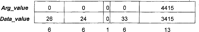
表15Table 15
拒绝了锁定响应且寄存器的字段成为:The lock response is rejected and the fields of the register become:

表16Table 16
将‘f’标记设为1,表示在该链路上再也没有信道了。link_bw_remaining字段显示出最终的更新值,即就是同意节点25的应用的请求之后。Set the 'f' flag to 1 to indicate that there are no more channels on the link. The link_bw_remaining field shows the final updated value, that is, after granting the application's request of the node 25 .
锁定响应包括了Source_PhyID、Sink_PhyID和Channel字段的值,以帮助呼叫方恢复其请求的内容。The Lock Response includes the values of the Source_PhyID, Sink_PhyID, and Channel fields to help the caller recover what it requested.
当预约或释放资源时,可以采用以下操作:When reserving or releasing resources, you can take the following actions:
“分配新值”:"assign new value":
该操作是分配新信道和带宽的数量。信道为可用、空闲的,所需的带宽是可用的。该操作被称为分配是因为在请求(′arg_value′)下发送的预先读取的带宽值要大于写入到link_bw_remaining字段(′data_value′)的新值。将channel_available标记置为0。The operation is to allocate a new channel and amount of bandwidth. The channel is available, idle, and the required bandwidth is available. This operation is called an allocation because the read-ahead bandwidth value sent under the request ('arg_value') is greater than the new value written to the link_bw_remaining field ('data_value'). Set channel_available flag to 0.
LRM记住了信道和已分配带宽之间的关系。LRM remembers the relationship between channels and allocated bandwidth.
根据不同的实施例,可以预约信道而不预约带宽。这种可能性可以由入口方决定。According to various embodiments, channels may be reserved but not bandwidth. This possibility can be determined by the entry party.
“分配更多”:"allocate more":
如果有足够多的可用带宽,该操作是向预先被分配的信道分配附加的带宽。LRM根据锁定请求的信道号对应着已被分配的信道这一事实来识别这种操作。将请求的带宽之差加到已被该信道预约的带宽中。channel_available标记保持为0。入口不能阻止在已分配信道预约带宽的应用发送另一个会在总线上引起混乱的数据流(同1394-1995一样)。This operation is to allocate additional bandwidth to a pre-assigned channel if there is enough bandwidth available. The LRM recognizes this operation by the fact that the channel number of the lock request corresponds to an already allocated channel. The difference in the requested bandwidth is added to the bandwidth already reserved for this channel. The channel_available flag remains at 0. Ingress cannot prevent an application reserving bandwidth on an allocated channel from sending another stream that would cause confusion on the bus (same as 1394-1995).
“完全释放”:"Full Release":
该操作是释放信道以及分配给该信道带宽。LRM将该操作识别为释放是因为锁定请求(包含了读取请求的结果)的(′arg_value′)字段小于其′data_value′(包含了要写入到link_bw_remaining字段的新值)。前两个字段之差等于(或大于)分配给该信道的带宽这一事实显示出资源的释放为完全释放的情况。将LINK_CHANNELS_AVAILABLE寄存器的信道标记置为空闲(1)。在锁定请求指出不止要释放已分配带宽情况下,只释放已分配的带宽。This operation is to release the channel and the bandwidth allocated to the channel. The LRM recognizes this operation as a release because the ('arg_value') field of the lock request (containing the result of the read request) is smaller than its 'data_value' (containing the new value to be written to the link_bw_remaining field). The fact that the difference between the first two fields is equal to (or greater than) the bandwidth allocated to the channel shows that the release of the resource is a complete release. Set the channel flag in the LINK_CHANNELS_AVAILABLE register to free (1). In cases where the lock request indicates that more than the allocated bandwidth is to be freed, only the allocated bandwidth is released.
“部分释放”:"Partial Release":
该操作是只释放给定信道的部分带宽.LRM根据锁定请求bw_remaining字段的′arg_value′小于其′data_value′这一事实将请求的操作识别为释放,而因为差值小于分配给该信道的带宽,则就是部分的.信道在LINK_CHANNELS_AVAILABLE寄存器中保持预约(对应的标记保持为值0).减去信道被释放的带宽并且使LRM与其保持联系.The operation is to release only part of the bandwidth of the given channel. The LRM recognizes the requested operation as a release based on the fact that the 'arg_value' of the bw_remaining field of the lock request is less than its 'data_value', and because the difference is less than the bandwidth allocated to the channel, Then it is partial. The channel remains reserved in the LINK_CHANNELS_AVAILABLE register (the corresponding flag remains at the value 0). Subtract the channel's freed bandwidth and keep the LRM associated with it.
在预约了链路上所有可用信道的情况下,将LINK_CHANNELS_AVAILABLE寄存器中所有的标记置为0。LRM仍然保持那些真正被应用预约的信道列表,以和那些只是在寄存器中被标记的信道相比较。当LRM接收到用于“分配更多”操作的锁定请求时,只有当该请求对应着真正预约的信道时,才会给该请求分配附加的带宽。In case all available channels on the link are reserved, all flags in the LINK_CHANNELS_AVAILABLE register are set to 0. The LRM still maintains a list of those channels that are actually reserved by the application, for comparison with those that are just marked in the register. When the LRM receives a lock request for an "allocate more" operation, it will allocate additional bandwidth to the request only if the request corresponds to a channel actually reserved.
5、利用LINK_CHANNELS_AVAILABLE寄存器的例子5. Example of using LINK_CHANNELS_AVAILABLE register
分别参照给出不同时刻寄存器内容的表17至表21,下文中给出了一个利用LINK_CHANNELS_AVAILABLE寄存器的例子。根据本例,无线链路的容量为三个信道。Referring to Table 17 to Table 21, which give the contents of the registers at different times, respectively, an example of using the LINK_CHANNELS_AVAILABLE register is given below. According to the example, the capacity of the radio link is three channels.
最初,没有使用无线链路上的信道。LINK_CHANNELS_AVAILABLE寄存器的状态由表17给出:Initially, the channels on the wireless link are not used. The status of the LINK_CHANNELS_AVAILABLE register is given by Table 17:
表17Table 17
例如第一个应用预约信道7。分配之后寄存器的状态由表18给出。For example, the first
表18Table 18
接着第二个应用预约信道33,寄存器的状态变为:Then the second
表19Table 19
在该链路上只剩下一个可用信道。当第三个应用分配信道2时,寄存器的状态变为:There is only one usable channel left on the link. When the third application allocates
表20Table 20
由于该链路不能提供更多信道,将所有的信道标记置为0。如果第四个应用读取了该链路的寄存器,它就会推断出没有信道可以预约了。Since the link cannot provide more channels, set all channel flags to 0. If a fourth application reads the link's registers, it will deduce that there are no channels left to reserve.
现在,如果第二个应用释放了信道33,寄存器的状态变为:Now, if the second application releases
表21Table 21
现在在无线链路上有一个信道是可用的:所有未使用信道的标记置为1。One channel is now available on the radio link: all unused channels have their flags set to 1.
有利地,首先需要由全局IRM来预约信道这一事实保证了不会出现与在多个无线链路上预约信道识别相关的冲突。如果首先不由IRM进行分配,则LRM不可能预约信道。Advantageously, the fact that the channel first needs to be reserved by the global IRM ensures that no conflicts will arise related to reserving channel identification on multiple wireless links. It is not possible for the LRM to reserve a channel if it is not first allocated by the IRM.
网络的应用可能认识或不认识到无线链路。在认识链路的应用创建了包括一个或更多无线链路的情况下,这些链路的LRM可以通过其自身预约请求的资源,或根据其他实施例,给由认识链路的应用做出的连接以优先权。Applications of the network may or may not be aware of the wireless link. In the event that a link-aware application creates a link that includes one or more wireless links, the LRM for these links may reserve the requested resources by itself, or, according to other embodiments, to a link made by the link-aware application. Connect with priority.
6、连接建立的方法6. The method of connection establishment
这里简要给出几种根据本实施例的认识链路使用的连接方法。这些方法涉及连接的打开、连接的破坏、总线复位之后连接的建立以及对已有连接的连接覆盖。Here, several connection methods for recognizing link usage according to this embodiment are briefly given. These methods concern opening of a connection, destruction of a connection, establishment of a connection after a bus reset, and connection overwriting of an existing connection.
在下面几个方法的例子中,为了判断在讲话者节点与听话者节点之间的通路上是否有一个或几个资源被预约的链路,应用需要获得网络的拓扑。In the following method examples, in order to judge whether there is one or several links with reserved resources on the path between the speaker node and the listener node, the application needs to obtain the topology of the network.
应用可以从在总线复位之后建立一拓扑图的IEEE1394物理层得到该拓扑图。该拓扑图表示了不同的节点是如何连接的。Applications can get this topology map from the
根据本实施例,每一个入口在其存储器中包含了用于指示它是入口的标识符。为了判断这些节点是否是入口,一旦应用得到拓扑图——这只在复位之后需要——就会访问网络上所有节点的存储器。当在拓扑图中连续检测到两个入口时,会识别链路。According to this embodiment, each entry contains in its memory an identifier indicating that it is an entry. In order to determine whether these nodes are portals, once the application gets the topology map - which is only needed after reset - it accesses the memory of all nodes on the network. Links are identified when two ingresses are detected consecutively in the topology map.
6.1打开连接6.1 Open the connection
为了打开连接,应用必须:In order to open a connection, an application must:
1判断网络的拓扑图并检查在源节点与宿节点之间的通路上是否有一个或几个链路。1. Judging the topology diagram of the network and checking whether there are one or several links on the path between the source node and the sink node.
2如果呼叫方客户(即应用)没有给出带宽,在源节点的输出插头控制寄存器(′oPCR′,与IEC61883的定义相同,说明了IEEE1394总线上同步数据流的传送)上执行读取请求以获取所需的带宽。2 If no bandwidth is given by the calling client (i.e. the application), perform a read request on the source node's output plug control register ('oPCR', same definition as IEC61883, which describes the transmission of isochronous data streams on the IEEE1394 bus) to Get the bandwidth you need.
3在下面基础上执行读取请求:3 Execute the read request on the following basis:
IRM BANDWIDTH_AVAILABLE寄存器(为了获得IEEE1394网络上可用带宽的数量);IRM BANDWIDTH_AVAILABLE register (in order to obtain the amount of bandwidth available on the IEEE1394 network);
IRM CHANNELS_AVAILABLE寄存器(为了获得IEEE1394网络上可用信道的列表);IRM CHANNELS_AVAILABLE register (in order to obtain a list of available channels on the IEEE1394 network);
LRM LINK_BANDWIDTH_AVAILABLE寄存器(为了获得各个链路上可用带宽的数量),用于由连接交叉形成的各个链路;LRM LINK_BANDWIDTH_AVAILABLE register (in order to obtain the amount of available bandwidth on each link), for each link formed by connection crossover;
LRM LINK_CHANNELS_AVAILABLE(为了检查信道的可用性),用于由连接交叉的各个链路;LRM LINK_CHANNELS_AVAILABLE (in order to check channel availability), for individual links crossed by connections;
宿节点的输入插头控制寄存器(IEC61883定义的′iPCR′),用于核实该节点为空闲且可以接收数据流。The sink node's input plug control register ('iPCR' as defined by IEC61883) is used to verify that the node is free and can receive data streams.
4在下面的基础上执行锁定请求:4 The lock request is performed on the following basis:
IRM BANDWIDTH_AVAILABLE寄存器(为了在IEEE1394网络上预约带宽);IRM BANDWIDTH_AVAILABLE register (in order to reserve bandwidth on the IEEE1394 network);
IRM CHANNELS_AVAILABLE寄存器(为了在IEEE1394网络上预约信道);IRM CHANNELS_AVAILABLE register (in order to reserve a channel on the IEEE1394 network);
5如果请求成功了,在下面的基础上执行锁定请求:5 If the request is successful, the lock request is performed on the following basis:
LRM LINK_BANDWIDTH_AVAILABLE寄存器,用于由连接交叉形成的各个链路(为了预约各个链路上的带宽),该寄存器包括源PhyID、宿PhyID以及在IRM已经被分配的信道号;The LRM LINK_BANDWIDTH_AVAILABLE register is used for each link formed by connection crossover (in order to reserve the bandwidth on each link), this register includes source PhyID, sink PhyID and channel number that has been allocated in IRM;
源的oPCR(为了调整该寄存器以显示出连接的存在)oPCR of the source (in order to adjust this register to show the existence of the connection)
宿的iPCR(为了调整该寄存器以显示出连接的存在)Sink's iPCR (in order to adjust this register to show the presence of a connection)
6.2关闭连接6.2 Closing the connection
为了关闭连接,应用必须:In order to close a connection, an application must:
1在下面的基础上执行读取请求:1 Performs a read request on the following basis:
源的oPCR核实该源没有被覆盖(即就是只连接了一个收听者节点部分)The source's oPCR verifies that the source is not covered (i.e. only part of a listener node is connected)
IRM BANDWIDTH_AVAILABLE寄存器;IRM BANDWIDTH_AVAILABLE register;
LRM LINK_BANDWIDTH_AVAILABLE寄存器,用于由连接交叉形成的各个链路。LRM LINK_BANDWIDTH_AVAILABLE register for individual links formed by connection crossovers.
2在下面的基础上执行锁定请求:2 The lock request is performed on the following basis:
IRM BANDWIDTH_AVAILABLE寄存器IRM BANDWIDTH_AVAILABLE register
IRM CHANNELS_AVAILABLE寄存器IRM CHANNELS_AVAILABLE register
LRM LINK_BANDWIDTH_AVAILABLE寄存器,用于由连接交叉形成的各个链路LRM LINK_BANDWIDTH_AVAILABLE register for individual links formed by connection crossovers
源节点的oPCRoPCR of the source node
宿节点的iPCRiPCR of sink node
6.2网络复位之后重建连接6.2 Reestablish connection after network reset
总线复位由链路传播。无论复位发生在何处,创建连接的应用都能意识到总线复位的发生。基本上,重建所遵循的规则与创建连接的规则相同。LRM寄存器与IRM寄存器复位的方式相同。A bus reset is propagated by the link. Applications creating connections are aware of bus resets regardless of where the reset occurred. Basically, rebuilding follows the same rules as creating connections. The LRM register is reset in the same way as the IRM register.
6.3覆盖连接6.3 Overlay connections
为了覆盖连接,应用必须:In order to override a connection, an application must:
1得到拓扑图,并检查在源节点与宿节点之间的通路上是否有一个或几个链路。推断出哪一个节点已经被连接预约。1 Get the topology map, and check whether there are one or several links on the path between the source node and the sink node. Infer which node has been reserved for a connection.
2在源的oPCR上执行读取请求,以了解所需的带宽(如果呼叫方客户没有给出带宽)。2 Perform a read request on the source's oPCR to know the required bandwidth (if the calling client didn't give it).
3在下面的基础上执行读取请求:3 Perform a read request on the following basis:
LRM LINK_BANDWIDTH_AVAILABLE寄存器(为了获得各个链路上可用带宽的数量),用于由连接交叉形成且没有被预约的各个链路。The LRM LINK_BANDWIDTH_AVAILABLE register (in order to obtain the amount of bandwidth available on each link) is used for each link formed by a connection cross and not reserved.
LRM LINK_CHANNELS_AVAILABLE寄存器(为了检查信道的可用性),用于由连接交叉形成且没有被预约的各个链路。LRM LINK_CHANNELS_AVAILABLE register (in order to check channel availability) for each link formed by connection crossing and not reserved.
宿节点的iPCR,用于核实该节点为空闲。The iPCR of the sink node is used to verify that the node is idle.
4在下面的基础上执行锁定请求:4 The lock request is performed on the following basis:
LRM LINK_BANDWIDTH_AVAILABLE寄存器(为了获得各个链路上可用带宽的数量),用于由连接交叉形成且没有被预约的各个链路;The LRM LINK_BANDWIDTH_AVAILABLE register (in order to obtain the amount of available bandwidth on each link) is used for each link formed by connection crossover and not reserved;
LRM LINK_CHANNELS_AVAILABLE寄存器,用于由连接交叉形成的各个链路,该寄存器包括源PhyID、宿PhyID以及在IRM已经分配的信道号。The LRM LINK_CHANNELS_AVAILABLE register is used for each link formed by connecting crosses. This register includes the source PhyID, sink PhyID, and channel numbers that have been allocated in the IRM.
源节点的oPCRoPCR of the source node
宿节点的iPCRiPCR of sink node
利用上述,应用可以检测到是否建立了连接以及哪个链路未能提供充分的资源。根据不是这里所述目的的方法,为了避免失败的连接,可以建议应用更改网络的拓扑图。Using the above, an application can detect if a connection is established and which link fails to provide sufficient resources. In order to avoid failed connections, the application may be advised to change the topology map of the network according to a method not intended for the purpose described here.
图8表示了图1的网络,其中源13和16分别与总线12和11相连以响应应用对用户的指示。Figure 8 shows the network of Figure 1 in which sources 13 and 16 are connected to buses 12 and 11 respectively in response to instructions from the application to the user.
7、带宽使用的改善7. Improved bandwidth usage
如果第一个应用在可提供30Mb/s的HiperLAN2链路上预约了20Mb/s带宽,但只用了10Mb/s,浪费了10Mb/s的带宽。需要15Mb/s的第二个应用就不能实现预约。If the first application reserves 20Mb/s bandwidth on the HiperLAN2 link that can provide 30Mb/s, but only uses 10Mb/s, 10Mb/s bandwidth is wasted. A second application that requires 15Mb/s cannot make the reservation.
根据变化实施例,链路的LRM核实与预约带宽相比应用的实际使用带宽并得到可用差额以用于其他应用的分配。According to a variant embodiment, the LRM of the link checks the actual used bandwidth of the application compared to the reserved bandwidth and obtains the available balance for the allocation of other applications.
图5所示的竖条表示了链路上的可用带宽。出于本例的目标,总可用带宽为10个单元。对于每一个应用预约的信道来说,LRM保留了两个参数。第一个参数(下文中标为’R’)表示被预约带宽。第二个参数(标为’O’)表示被预约带宽与信道上应用实际使用带宽之差。O表示用于该信道的最优化带宽。The vertical bars shown in Figure 5 represent the available bandwidth on the link. For the purposes of this example, the total available bandwidth is 10 units. For each channel reserved by an application, the LRM reserves two parameters. The first parameter (marked as 'R' hereinafter) indicates the reserved bandwidth. The second parameter (labeled 'O') represents the difference between the reserved bandwidth and the actual bandwidth used by the application on the channel. O represents the optimal bandwidth for this channel.
根据图5中例子,三个应用(A1,A2,A3)依次预约带宽。字母R和O旁边的数值分别表示了用于各个应用的带宽值。According to the example in Fig. 5, three applications (A1, A2, A3) reserve bandwidth in sequence. The values next to the letters R and O indicate the bandwidth values for each application, respectively.
第一个应用A1在信道7上预约了3个单元(步骤1),但LRM推断出A1只使用了一个。将用于A1的参数O置为值2(步骤2)。接着应用A2在信道33上预约了4个单元(步骤3),但只使用了两个:用于该应用的参数O也为值2(步骤4)。最后,应用A3在信道2上预约了4个单元并且全部都使用了(步骤5)。这样可以将3个单元分配给其他的应用并且LRM适当地设置新的link_bw_available值。The first application A1 reserves 3 units on channel 7 (step 1), but the LRM deduces that A1 only uses one. Parameter O for A1 is set to the value 2 (step 2). Application A2 then reserves 4 units on channel 33 (step 3), but only uses two: the parameter O for this application also has the value 2 (step 4). Finally, application A3 reserves 4 units on
图6表示了当应用开始释放带宽时图5中的带宽。由于应用没有意识到自己并没有把预约的带宽全部留给自己使用,它们会利用适当的锁定请求释放预约的数量。Figure 6 shows the bandwidth in Figure 5 when the application starts to release bandwidth. Since applications do not realize that they do not have all the reserved bandwidth reserved for their own use, they will release the reserved amount with the appropriate locking request.
假设应用A1希望释放其信道和带宽(步骤6)。它会发送试图将link_bw_available值增大到3的锁定请求,即三个单元。LRM会利用包括link_bw_available值增加三个单元的正锁定请求来假装释放应用A1的三个单元,但实际上只会用实际使用的单元数量,即1,来有效地增加该值。应用于A3和A2的资源释放概念是相同的。Assume that application A1 wishes to release its channel and bandwidth (step 6). It sends a lock request trying to increase the link_bw_available value to 3, or three units. The LRM will pretend to release three units of application A1 with a positive lock request that includes an increase in the value of link_bw_available by three units, but will actually only effectively increase the value by the number of units actually used, which is 1. The concept of resource release applied to A3 and A2 is the same.
根据这个过程,应用可能必须使在其锁定请求中使用大于在LINK_BANDWIDTH_AVAILABLE寄存器中给出的最大带宽的带宽值。例如在步骤8,为了释放带宽的4个单元,由于寄存器的当前值是8,应用A2会在其锁定请求中使用期待值(′data_value′)12。Depending on this procedure, the application may have to use a bandwidth value greater than the maximum bandwidth given in the LINK_BANDWIDTH_AVAILABLE register in its lock requests. For example in
不过,应用的带宽释放肯定不会导致使用的带宽值超过0X1FFF,这是因为该值表示的是为该目标预约的13位编码的最大值。因此,LRM提供的一个信道上带宽的改善不会大于0X1FFF减去链路上可用带宽的最大值。However, the bandwidth release of the application will definitely not cause the used bandwidth value to exceed 0X1FFF, because this value represents the maximum value of the 13-bit encoding reserved for this object. Therefore, the improvement in bandwidth on one channel provided by LRM will not be greater than 0X1FFF minus the maximum bandwidth available on the link.
例如,链路带宽为0X1333时,用于任意一个信道改善的最大值不会超过0XCCC。For example, when the link bandwidth is 0X1333, the maximum value for any channel improvement will not exceed 0XCCC.
8、利用单一链路的多个网络互连8. Multiple network interconnections using a single link
根据变化实施例,几个类型的网络可以同时使用网络。图8所示为包含了四个入口74至77的链路框图。入口74和75分别与两个IEEE1394总线70和71相连接。入口76和77分别与两个IP网络72和73相连接。链路以透明方式连接两个总线70和71,即就是说,在较低层认为所有的总线设备在单一总线上。对于IP网络来说也是如此:认为所有的IP设备在单一IP网络上。总线70/71组成的网络以及IP网72/73的网络均忽略了其他网络的存在。它们仍然可以共享使用由入口74到77形成的链路资源。入口可以包括在单一设备中或由分离设备形成(例如在无线链路的情况下)。According to a variant embodiment, several types of networks may use the network at the same time. FIG. 8 shows a block diagram of a chain comprising four
入口必须将网络资源分配给所有网络类型。根据本实施例,会给各种类型的网络提供单独的LRM。在本例的情况下,给IEEE1394总线的网络提供了一个LRM,并给IP网络提供了一个LRM。在下文中将这两个LRM称为LRM-1394和LRM-IP。LRM-IP向IP设备提供的接口不需要与LRM1394向LRM1394节点提供的相同。Ingress must allocate network resources to all network types. According to this embodiment, separate LRMs are provided for each type of network. In the case of this example, one LRM is provided for the network of the IEEE1394 bus, and one LRM is provided for the IP network. These two LRMs are hereinafter referred to as LRM-1394 and LRM-IP. The interface provided by LRM-IP to IP devices need not be the same as that provided by LRM1394 to LRM1394 nodes.
由于这两个LRM被分配了相同的资源,它们根据链路实际的操作交换有关资源分配的信息。Since the two LRMs are allocated the same resources, they exchange information about resource allocation according to the actual operation of the link.
前面已经讨论过,即使链路的容量更大,例如在两个总线之间链路上使用的带宽通常也不会超过总线上的可用带宽。在现在这种情况下,几个网络竞争相同资源这种情况对于仅在确定环境中的给定网络会有限制效果。As discussed earlier, the bandwidth used on a link between two buses, for example, usually does not exceed the bandwidth available on the bus, even if the capacity of the link is greater. In the present case, the situation where several networks compete for the same resource has a limiting effect on a given network only in certain circumstances.
考虑下面这种情况:Consider the following situation:
链路带宽大于IEEE1394带宽。Link bandwidth is larger than IEEE1394 bandwidth.
在这种情况下,除非被IP网预约的带宽使总的链路带宽减少到小于0X1333带宽单元(IEEE1394单元),否则在IP网上预约的带宽不会减少LRM-1394的LINK_BANDWIDTH_AVAILABLE寄存器中bw_remaining的值。In this case, unless the bandwidth reserved by the IP network reduces the total link bandwidth to less than 0X1333 bandwidth units (IEEE1394 units), the bandwidth reserved on the IP network will not reduce the value of bw_remaining in the LINK_BANDWIDTH_AVAILABLE register of LRM-1394 .
将同样的行为应用于信道。Apply the same behavior to channels.
预约是真实的(即IEEE1394网络的带宽和信道预约)The reservation is real (that is, the bandwidth and channel reservation of the IEEE1394 network)
9、LRM选择9. LRM selection
本发明作用于点对点链路(每个网络只包括一对入口)和多点网络(每个网络包括多于两个入口)。在这两种情况下,在给定网络中LRM设备的选择存在两种可能性:一个入口(对每个网络而言)承担LRM的任务且所有应用向该设备发送消息;或是各个应用向与其连接的入口发送消息且链路内部的专用协议使入口同步。The invention works on point-to-point links (each network includes only one pair of entries) and multipoint networks (each network includes more than two entries). In both cases, there are two possibilities for the selection of an LRM device in a given network: one portal (for each network) assumes the role of LRM and all applications send messages to this device; The portals connected to it send messages and a dedicated protocol inside the link synchronizes the portals.
换句话说,在第一种情况下,由从所有候选入口中选出的单一入口来管理LRM,各个应用都了解当选的入口,而在第二种情况下,没有进行选择且各个应用都不知道LRM的位置,只是简单地将请求发送到距离它们最近的入口。In other words, in the first case, the LRM is managed by a single entry selected from among all the candidate entries, and each application is aware of the selected entry, while in the second case, no selection is made and each application has no Knowing the location of the LRMs simply sends the request to the entrance closest to them.
在包括了链路的网络为IEEE1394总线网络情况下,现在对这两种可能性进行说明。These two possibilities are now explained in case the network comprising the links is an IEEE1394 bus network.
(a)单一LRM入口选择(a) Single LRM entry selection
一个入口承担LRM的任务。在网络或总线复位期间执行选择。这里将介绍两种选择LRM入口的选择方法。第一种方法基于对网络拓扑图的分析。第二种方法基于入口的选择,随后是向应用宣布或公开当选LRM的物理识别符。One portal takes over the task of the LRM. The selection is performed during a network or bus reset. Two selection methods for selecting the LRM entry will be introduced here. The first method is based on the analysis of network topology graphs. The second method is based on the selection of an entry, followed by announcing or disclosing to the application the physical identifier of the elected LRM.
拓扑算法topology algorithm
根据本方法,候选入口中PhyID值最大的入口当选为LRM。这种算法的优点在于非常简单,这是因为很容易利用到来自IEEE1394层的拓扑。在每次总线复位之后,应用必须检查拓扑以确定各个链路的LRM。According to this method, the entry with the largest PhyID value among the candidate entries is selected as the LRM. The advantage of this algorithm is that it is very simple, because it is easy to use the topology from the IEEE1394 layer. After each bus reset, the application must examine the topology to determine the LRM for each link.
专用链路选择Dedicated Link Selection
该方法执行了链路(根据链路的特殊协议,即入口之间)“内部”的动态协议,这意味着在总线复位之后可以更换LRM(例如如果删除了是LRM的入口)。This method implements a dynamic protocol "inside" the link (according to the specific protocol of the link, ie between entries), which means that the LRM can be replaced after a bus reset (for example if an entry that is an LRM is deleted).
而且,为了使IEEE1394应用了解哪个节点表示LRM,在入口的配置存储器(′config rom′)中定义特定的条目,这个新条目存在于所有入口设备的配置存储器中。Also, in order for the IEEE1394 application to know which node represents the LRM, a specific entry is defined in the configuration memory ('config rom') of the portal, this new entry exists in the configuration memory of all portal devices.
表22给出了根据本例的存储器条目的格式。可能是其他格式。Table 22 shows the format of the memory entry according to this example. May be other formats.

表22Table 22
‘s’为同步位。当‘s’为’1’时,认为Phy ID值不是最新值且现在正在改变。这可能发生在例如总线复位之后。当‘s’等于’0’时,Phy ID值表示用于此链路的LRM的Phy ID。更新Phy ID值的方法是链路专用的。's' is the synchronization bit. When 's' is '1', the Phy ID value is considered not up-to-date and is now changing. This can happen, for example, after a bus reset. When 's' is equal to '0', the Phy ID value indicates the Phy ID of the LRM used for this link. The method to update the Phy ID value is link specific.
(b)无LRM入口选择(b) No LRM entry option
根据第二种方法,各个应用向与其连接的入口发送消息(即读取请求和锁定请求)。每一个入口执行LRM寄存器。链路内部的专用协议实现了入口之间的同步以避免同时发生的多锁定请求引起的冲突。According to the second method, each application sends messages (ie read requests and lock requests) to the portals it is connected to. Each entry executes the LRM register. A dedicated protocol within the link implements synchronization between entries to avoid conflicts caused by simultaneous multiple lock requests.
Claims (9)
Applications Claiming Priority (5)
| Application Number | Priority Date | Filing Date | Title |
|---|---|---|---|
| EP01113121 | 2001-05-29 | ||
| EP01113121.6 | 2001-05-29 | ||
| EP01114652A EP1263172A3 (en) | 2001-05-29 | 2001-06-19 | Method for managing resources of a link in a communication network |
| EP01114652.9 | 2001-06-19 | ||
| PCT/EP2002/005715 WO2002098070A1 (en) | 2001-05-29 | 2002-05-24 | Method for managing resources of a link in a communication network |
Publications (2)
| Publication Number | Publication Date |
|---|---|
| CN1663193A CN1663193A (en) | 2005-08-31 |
| CN1663193B true CN1663193B (en) | 2010-05-12 |
Family
ID=26076600
Family Applications (1)
| Application Number | Title | Priority Date | Filing Date |
|---|---|---|---|
| CN028107578A Expired - Fee Related CN1663193B (en) | 2001-05-29 | 2002-05-24 | Method for managing link resources in a communication network |
Country Status (9)
| Country | Link |
|---|---|
| US (1) | US7277456B2 (en) |
| EP (2) | EP1263172A3 (en) |
| JP (1) | JP4124725B2 (en) |
| KR (1) | KR100815581B1 (en) |
| CN (1) | CN1663193B (en) |
| DE (1) | DE60205113T2 (en) |
| ES (1) | ES2245738T3 (en) |
| MX (1) | MXPA03010876A (en) |
| WO (1) | WO2002098070A1 (en) |
Families Citing this family (17)
| Publication number | Priority date | Publication date | Assignee | Title |
|---|---|---|---|---|
| US6865607B1 (en) * | 2001-06-28 | 2005-03-08 | Microsoft Corp. | Pluggable channels |
| CN1278517C (en) * | 2002-05-27 | 2006-10-04 | 华为技术有限公司 | Full distribution type managing method for realizing interworking between wideband and narrowband signaling networks |
| US7693058B2 (en) * | 2002-12-03 | 2010-04-06 | Hewlett-Packard Development Company, L.P. | Method for enhancing transmission quality of streaming media |
| JP2005012260A (en) * | 2003-06-16 | 2005-01-13 | Matsushita Electric Ind Co Ltd | Data transmission control method |
| US7995606B1 (en) * | 2003-12-03 | 2011-08-09 | Apple Inc. | Fly-by and ack-accelerated arbitration for broadcast packets |
| US7551606B2 (en) * | 2004-08-20 | 2009-06-23 | Sony Corporation | Isochronous transmission for IP-oriented network |
| CN100375446C (en) * | 2005-04-15 | 2008-03-12 | 中兴通讯股份有限公司 | Availability management method for asynchronous transfer mode adaptation layer 2 service channel |
| US7548547B2 (en) * | 2006-03-31 | 2009-06-16 | Microsoft Corporation | Controlling the transfer of terminal server data |
| US7639612B2 (en) * | 2006-05-02 | 2009-12-29 | Mcewen Kathy | System and method of providing bandwidth on demand |
| JP2007324681A (en) * | 2006-05-30 | 2007-12-13 | Funai Electric Co Ltd | Devices connected to the IEEE serial bus |
| US9219670B2 (en) * | 2007-02-05 | 2015-12-22 | Microsoft Technology Licensing, Llc | Link-aware throughput acceleration profiles |
| JP4834148B2 (en) * | 2007-03-30 | 2011-12-14 | 富士通セミコンダクター株式会社 | Data transfer method and data transfer apparatus |
| CN101335698B (en) * | 2007-06-28 | 2012-06-27 | 日电(中国)有限公司 | Method and apparatus of channel allocation in multi-frequency antenna mesh network |
| JP5321349B2 (en) * | 2009-08-24 | 2013-10-23 | 富士通セミコンダクター株式会社 | Data transfer method and data transfer apparatus |
| US8782237B2 (en) | 2010-01-28 | 2014-07-15 | Intel Corporation | Audio/video streaming in a topology of devices |
| KR101045000B1 (en) * | 2010-10-25 | 2011-06-29 | 문영훈 | Removable Plywood Support |
| US20150173116A1 (en) * | 2013-12-13 | 2015-06-18 | Mediatek Inc. | Communications method, device and system |
Citations (1)
| Publication number | Priority date | Publication date | Assignee | Title |
|---|---|---|---|---|
| US6389496B1 (en) * | 1998-01-29 | 2002-05-14 | Nec Corporation | Bridge including portals with ability to redefine network topology |
Family Cites Families (5)
| Publication number | Priority date | Publication date | Assignee | Title |
|---|---|---|---|---|
| US6611891B1 (en) * | 1998-11-23 | 2003-08-26 | Advanced Micro Devices, Inc. | Computer resource configuration mechanism across a multi-pipe communication link |
| JP3449313B2 (en) * | 1999-09-28 | 2003-09-22 | 日本電気株式会社 | Device information collection method, device control device, and bridge |
| AU3643801A (en) * | 1999-11-29 | 2001-06-04 | Sony Electronics Inc. | Method and system for adjusting isochronous bandwidths on a bus |
| JP3454217B2 (en) * | 1999-12-28 | 2003-10-06 | 日本電気株式会社 | Communication path control method, device control device, and bridge |
| DE69940781D1 (en) * | 1999-12-30 | 2009-06-04 | Sony Deutschland Gmbh | Interface connection layer device for establishing a distributed network |
-
2001
- 2001-06-19 EP EP01114652A patent/EP1263172A3/en not_active Withdrawn
-
2002
- 2002-05-24 ES ES02738103T patent/ES2245738T3/en not_active Expired - Lifetime
- 2002-05-24 US US10/479,136 patent/US7277456B2/en not_active Expired - Fee Related
- 2002-05-24 EP EP02738103A patent/EP1391088B1/en not_active Expired - Lifetime
- 2002-05-24 JP JP2003501141A patent/JP4124725B2/en not_active Expired - Fee Related
- 2002-05-24 CN CN028107578A patent/CN1663193B/en not_active Expired - Fee Related
- 2002-05-24 WO PCT/EP2002/005715 patent/WO2002098070A1/en not_active Ceased
- 2002-05-24 DE DE60205113T patent/DE60205113T2/en not_active Expired - Lifetime
- 2002-05-24 MX MXPA03010876A patent/MXPA03010876A/en active IP Right Grant
- 2002-05-24 KR KR1020037015385A patent/KR100815581B1/en not_active Expired - Fee Related
Patent Citations (1)
| Publication number | Priority date | Publication date | Assignee | Title |
|---|---|---|---|---|
| US6389496B1 (en) * | 1998-01-29 | 2002-05-14 | Nec Corporation | Bridge including portals with ability to redefine network topology |
Also Published As
| Publication number | Publication date |
|---|---|
| EP1263172A2 (en) | 2002-12-04 |
| US20040151153A1 (en) | 2004-08-05 |
| EP1391088A1 (en) | 2004-02-25 |
| KR100815581B1 (en) | 2008-03-24 |
| DE60205113T2 (en) | 2006-05-24 |
| EP1263172A3 (en) | 2002-12-18 |
| US7277456B2 (en) | 2007-10-02 |
| JP2004527987A (en) | 2004-09-09 |
| KR20040028765A (en) | 2004-04-03 |
| WO2002098070A1 (en) | 2002-12-05 |
| CN1663193A (en) | 2005-08-31 |
| MXPA03010876A (en) | 2004-02-17 |
| JP4124725B2 (en) | 2008-07-23 |
| DE60205113D1 (en) | 2005-08-25 |
| ES2245738T3 (en) | 2006-01-16 |
| EP1391088B1 (en) | 2005-07-20 |
Similar Documents
| Publication | Publication Date | Title |
|---|---|---|
| CN1663193B (en) | Method for managing link resources in a communication network | |
| US7035279B2 (en) | Flow allocation in a ring topology | |
| JP4689130B2 (en) | Isochronous resource management method in a network based on HIPERLAN type 2 | |
| EP1327328B1 (en) | Method for linking several communication busses using wireless links | |
| US6374316B1 (en) | Method and system for circumscribing a topology to form ring structures | |
| CN100530161C (en) | Dynamic special purpose processors communication network capable of providing port | |
| JP4443225B2 (en) | Method and apparatus for managing connections in a communication network having a bridge | |
| JP2005510180A (en) | Method and apparatus for assigning addresses in packet transmission over a transparent bridge | |
| CN1321512C (en) | Method of managing a communication network comprising wireless links of more than two wireless devices | |
| US6584539B1 (en) | Method and system for message broadcast flow control on a bus bridge interconnect | |
| KR100828064B1 (en) | How to reserve isochronous resources in a network that includes a wireless link | |
| EP1499071A1 (en) | Apparatus, method, program and information recording medium for data rate setting | |
| US20060050656A1 (en) | Method for determining a parent portal in a wireless network and corresponding portal device | |
| JP2002517967A (en) | IEEE 1394 serial bus topology optimization method |
Legal Events
| Date | Code | Title | Description |
|---|---|---|---|
| C06 | Publication | ||
| PB01 | Publication | ||
| C10 | Entry into substantive examination | ||
| SE01 | Entry into force of request for substantive examination | ||
| C14 | Grant of patent or utility model | ||
| GR01 | Patent grant | ||
| CF01 | Termination of patent right due to non-payment of annual fee | ||
| CF01 | Termination of patent right due to non-payment of annual fee |
Granted publication date: 20100512 Termination date: 20160524 |