CN1663170A - Broadcast router with shared configuration repository - Google Patents
Broadcast router with shared configuration repository Download PDFInfo
- Publication number
- CN1663170A CN1663170A CN03814569.3A CN03814569A CN1663170A CN 1663170 A CN1663170 A CN 1663170A CN 03814569 A CN03814569 A CN 03814569A CN 1663170 A CN1663170 A CN 1663170A
- Authority
- CN
- China
- Prior art keywords
- card
- router
- configuration
- present
- memory sub
- Prior art date
- Legal status (The legal status is an assumption and is not a legal conclusion. Google has not performed a legal analysis and makes no representation as to the accuracy of the status listed.)
- Granted
Links
Images

Classifications
-
- H—ELECTRICITY
- H04—ELECTRIC COMMUNICATION TECHNIQUE
- H04L—TRANSMISSION OF DIGITAL INFORMATION, e.g. TELEGRAPHIC COMMUNICATION
- H04L45/00—Routing or path finding of packets in data switching networks
- H04L45/60—Router architectures
-
- H—ELECTRICITY
- H04—ELECTRIC COMMUNICATION TECHNIQUE
- H04L—TRANSMISSION OF DIGITAL INFORMATION, e.g. TELEGRAPHIC COMMUNICATION
- H04L45/00—Routing or path finding of packets in data switching networks
-
- H—ELECTRICITY
- H04—ELECTRIC COMMUNICATION TECHNIQUE
- H04L—TRANSMISSION OF DIGITAL INFORMATION, e.g. TELEGRAPHIC COMMUNICATION
- H04L45/00—Routing or path finding of packets in data switching networks
- H04L45/16—Multipoint routing
-
- H—ELECTRICITY
- H04—ELECTRIC COMMUNICATION TECHNIQUE
- H04L—TRANSMISSION OF DIGITAL INFORMATION, e.g. TELEGRAPHIC COMMUNICATION
- H04L45/00—Routing or path finding of packets in data switching networks
- H04L45/56—Routing software
- H04L45/563—Software download or update
-
- H—ELECTRICITY
- H04—ELECTRIC COMMUNICATION TECHNIQUE
- H04L—TRANSMISSION OF DIGITAL INFORMATION, e.g. TELEGRAPHIC COMMUNICATION
- H04L49/00—Packet switching elements
- H04L49/20—Support for services
- H04L49/201—Multicast operation; Broadcast operation
-
- H—ELECTRICITY
- H04—ELECTRIC COMMUNICATION TECHNIQUE
- H04L—TRANSMISSION OF DIGITAL INFORMATION, e.g. TELEGRAPHIC COMMUNICATION
- H04L49/00—Packet switching elements
- H04L49/25—Routing or path finding in a switch fabric
- H04L49/253—Routing or path finding in a switch fabric using establishment or release of connections between ports
- H04L49/254—Centralised controller, i.e. arbitration or scheduling
-
- H—ELECTRICITY
- H04—ELECTRIC COMMUNICATION TECHNIQUE
- H04L—TRANSMISSION OF DIGITAL INFORMATION, e.g. TELEGRAPHIC COMMUNICATION
- H04L49/00—Packet switching elements
- H04L49/45—Arrangements for providing or supporting expansion
-
- H—ELECTRICITY
- H04—ELECTRIC COMMUNICATION TECHNIQUE
- H04L—TRANSMISSION OF DIGITAL INFORMATION, e.g. TELEGRAPHIC COMMUNICATION
- H04L49/00—Packet switching elements
- H04L49/55—Prevention, detection or correction of errors
- H04L49/552—Prevention, detection or correction of errors by ensuring the integrity of packets received through redundant connections
Landscapes
- Engineering & Computer Science (AREA)
- Computer Networks & Wireless Communication (AREA)
- Signal Processing (AREA)
- Computer Security & Cryptography (AREA)
- Data Exchanges In Wide-Area Networks (AREA)
- Small-Scale Networks (AREA)
- Programmable Controllers (AREA)
Abstract
一种广播路由器(100),包括:多个输入卡(136-1到136-N)、第一和第二路由器矩阵卡(134A和134B)、和多个输出卡(138-1到138-M)。存在于请求配置的卡上的可编程器件(142-1到142-M)发出配置请求到与共享配置信息储存库(146)一起存在于配置控制卡(140)上的主控制器(148)。在允许另外的可编程器件请求配置的时间段过去之后,主控制器(148)轮询存在于卡上的可编程器件,以确定可编程器件中的哪一个已请求了配置,并且使用保存在共享配置信息储存库(146)中的配置信息来配置已经请求配置的每一个可编程器件。
A broadcast router (100) includes: a plurality of input cards (136-1 to 136-N), first and second router matrix cards (134A and 134B), and a plurality of output cards (138-1 to 138-M). A programmable device (142-1 to 142-M) on a card requesting configuration issues a configuration request to a master controller (148) on a configuration control card (140) along with a shared configuration information repository (146). After a time period allowing additional programmable devices to request configuration has elapsed, the master controller (148) polls the programmable devices on the cards to determine which of the programmable devices has requested configuration, and configures each programmable device that has requested configuration using the configuration information stored in the shared configuration information repository (146).
Description
本申请涉及2002年6月21日提出的美国临时专利申请第60/390,347号。This application is related to US Provisional Patent Application Serial No. 60/390,347, filed June 21,2002.
本申请还涉及如下序号的同时待审美国专利申请:This application is also related to co-pending U.S. patent applications with the following serial numbers:
PCT/__(代理人案号IU010620),PCT/__(代理人案号IU020157),PCT/___ (Attorney's Case No. IU010620), PCT/___ (Attorney's Case No. IU020157),
PCT/__(代理人案号IU020158),PCT/__(代理人案号IU020159),PCT/___ (attorney case number IU020158), PCT/___ (attorney case number IU020159),
PCT/__(代理人案号IU020160),PCT/__(代理人案号IU020161),PCT/____ (Attorney's Docket No. IU020160), PCT/___ (Attorney's Docket No. IU020161),
PCT/__(代理人案号IU020162),PCT/__(代理人案号IU020252),PCT/___ (Attorney's Case No. IU020162), PCT/___ (Attorney's Case No. IU020252),
PCT/__(代理人案号IU020253),PCT/__(代理人案号IU020254)和PCT/___ (Attorney Docket No. IU020253), PCT/___ (Attorney Docket No. IU020254) and
PCT/__(代理人案号IU020255),所有这些申请都转让给本申请的受让人,特此全文引用,以供参考。PCT/___ (Attorney Docket No. IU020255), all of which are assigned to the assignee of the present application, are hereby incorporated by reference in their entirety.
技术领域technical field
本发明涉及可编程器件,尤其涉及具有多个卡的系统,所述多个卡中的每一个具有一个或多个可利用共享配置储存库来配置的可编程器件。The present invention relates to programmable devices, and more particularly to systems having multiple cards each having one or more programmable devices configurable using a shared configuration repository.
背景技术Background technique
广播路由器使得其多个输出中的每一个都被分配了来自于到达该广播路由器的多个输入中的任何一个的信号。例如,N×M广播路由器含有N个输入端和M个输出端,这N个输入端和M个输出端通过使N个输入端的任何一个施加给M个输出端的每一个的路由器矩阵二耦合在一起。许多这样的广播路由器,尤其是较大的广播路由器包含单个容纳了多个一般称为“卡”的印刷电路板的机架,所述多个印刷电路板以各种结构进行互联。常常,广播路由器中容纳的许多卡是在同一广播路由器中容纳的其他卡的副本。例如,在前面通过引用并入于此的同时待审美国专利申请第10/__(代理人案号IU010620)号中,公开了1280×1280的广播路由器,在构造该广播路由器时需要使用每一个都具有32个输入端的40个相同配置的输入卡。A broadcast router has each of its outputs assigned a signal from any one of its inputs. For example, an N x M broadcast router contains N inputs and M outputs coupled by a
通常,一个或多个现场可编程门阵列(或“FPGA”)存在于这样的卡上。FPGA是一种可以在制造之后在现场进行编程的集成电路。当通过对在其中安装了例如前述承载有一个或多个FPGA的卡的广播路由器加电,或通过在加电之后将该卡插入(或“热-插入”)到广播路由器的输入/输出(或“I/O”)总线,来对所述卡加电时,必须配置在该卡上的FPGA。传统的,已通过存储器件配置了FPGA,所述存储器件例如是与FPGA一起存在于该卡上的可编程只读存储器(或“PROM”)。但是,以这种方式来配置FPGA使得在每一个承载请求配置的FPGA或其他可编程器件的卡上复制需要的配置电路和数据存储器件。这样的配置技术被证明是昂贵的,尤其是对于包含有多个在其上存在请求配置的器件的广播路由器或其他系统。Typically, one or more Field Programmable Gate Arrays (or "FPGAs") reside on such cards. An FPGA is an integrated circuit that can be programmed in the field after manufacture. When either by powering up the broadcast router in which, for example, the aforementioned card carrying one or more FPGAs is installed, or by inserting (or "hot-plugging") the card into the input/output ( or "I/O") bus to power up the card, the FPGA on the card must be configured. Traditionally, an FPGA has been configured by a memory device, such as a programmable read-only memory (or "PROM") that resides with the FPGA on the card. However, configuring the FPGA in this manner duplicates the required configuration circuitry and data storage devices on each card carrying the FPGA or other programmable device requesting configuration. Such configuration techniques prove to be expensive, especially for broadcast routers or other systems that contain multiple devices on which configuration requests exist.
发明内容Contents of the invention
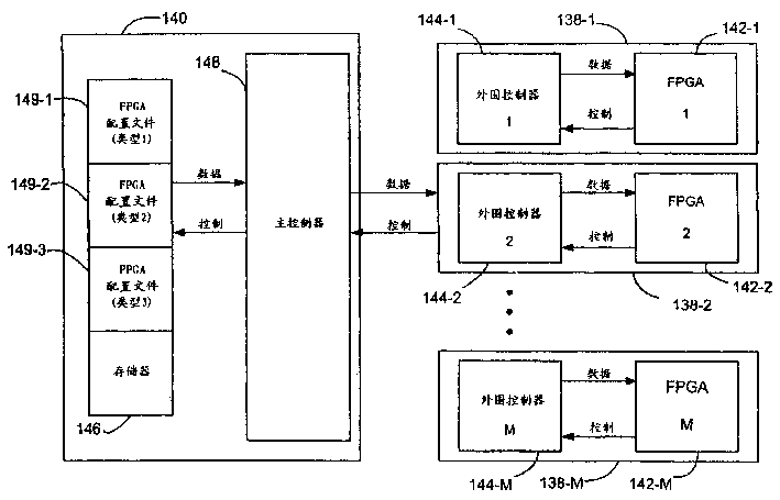
提供一种包括多个功能卡的电子系统,每一个功能卡具有至少一个存在于其上的可编程器件。该电子系统还包括耦合至多个功能卡中的每一个的配置控制卡,用于配置存在于多个功能卡上的可编程器件。在本发明的一个方面,存在于配置控制卡上的存储器件作为共享配置信息储存库,用于保存当配置存在于多个功能卡上的可编程器件时使用的配置信息。在另一个方面,通过存在于配置控制卡上的主控制器和存在于功能卡上的外围控制器来控制存在于多个功能卡中的一个卡上的可编程器件的配置。在这一方面,外围控制器用于将来源于可编程器件的配置请求转送到主控制器。转而,主控制器从存储器子系统检索配置信息,并将检索的信息转送到外围控制器。外围控制器随后将接收到的配置信息转送到进行请求的可编程器件。An electronic system is provided that includes a plurality of function cards, each function card having at least one programmable device residing thereon. The electronic system also includes a configuration control card coupled to each of the plurality of function cards for configuring programmable devices residing on the plurality of function cards. In one aspect of the present invention, the storage device on the configuration control card is used as a shared configuration information repository for storing configuration information used when configuring programmable devices on multiple function cards. In another aspect, configuration of a programmable device residing on one of the plurality of function cards is controlled by a host controller residing on a configuration control card and a peripheral controller residing on a function card. In this aspect, the peripheral controller is used to forward configuration requests originating from the programmable device to the main controller. In turn, the host controller retrieves configuration information from the memory subsystem and forwards the retrieved information to the peripheral controller. The peripheral controller then forwards the received configuration information to the requesting programmable device.
在本发明的又一个实施例中,电子系统是广播路由器,所述多个功能卡可以包括广播路由器的输入卡、输出卡和/或路由器卡,并且可编程器件可以是FPGA。In yet another embodiment of the present invention, the electronic system is a broadcast router, the plurality of function cards may include an input card, an output card and/or a router card of the broadcast router, and the programmable device may be an FPGA.
附图说明Description of drawings
图1是全冗余线性可扩展广播路由器的方块图;Fig. 1 is a block diagram of a fully redundant linear scalable broadcast router;
图2是图1的全冗余线性可扩展广播路由器的第一广播路由器部件的放大方块图;Figure 2 is an enlarged block diagram of a first broadcast router component of the fully redundant linearly scalable broadcast router of Figure 1;
图3是图2的第一广播路由器部件的一部分的放大方块图;Figure 3 is an enlarged block diagram of a portion of the first broadcast router component of Figure 2;
图4A和4B是配置存在于图2的第一广播路由器部件中的可编程器件的方法的流程图。4A and 4B are flowcharts of a method of configuring a programmable device present in the first broadcast router component of FIG. 2 .
具体实施方式Detailed ways
首先参照图1,现在更详细地描述全冗余线性可扩展广播路由器100。正如现在所看到的那样,全冗余线性可扩展广播路由器100包括相互耦合以形成较大全冗余线性可扩展广播路由器100的数个广播路由器部件。每个广播路由器部件是包括第一和第二路由器矩阵的分离路由器设备,第二路由器矩阵是第一路由器矩阵的冗余。因此,每个广播路由器含有第一和第二路由引擎,分别用于第一和第二路由器矩阵之一,每一个路由引擎在它的输入端接收相同的输入数字音频数据流,并在其输出端上放置相同的输出数字音频数据流。正如此处所公开的那样,用于构造全冗余线性可扩展广播路由器的每个广播路由器部件都是N×M大小的广播路由器。但是,完全可以设想,全冗余线性可扩展广播路由器100可以替换为由大小彼此不同的广播路由器部件构成。Referring first to FIG. 1 , fully redundant linear scalable broadcast router 100 will now be described in more detail. As can now be seen, fully redundant linearly scalable broadcast router 100 includes several broadcast router components coupled to each other to form a larger fully redundant linearly scalable broadcast router 100 . Each broadcast router component is a separate router device comprising first and second router matrices, the second router matrix being redundant to the first router matrix. Thus, each broadcast router contains first and second routing engines, respectively for one of the first and second router matrices, each routing engine receiving at its input the same input digital audio data stream and outputting at its output The same output digital audio data stream is placed on the terminal. As disclosed herein, each broadcast router component used to construct a fully redundant linearly scalable broadcast router is an NxM sized broadcast router. However, it is entirely conceivable that the fully redundant linearly scalable broadcast router 100 may instead be composed of broadcast router components of different sizes from each other.
正如此处进一步公开的那样,全冗余线性可扩展广播路由器100是通过将第一、第二、第三和第四广播路由器部件102、104、106和108耦合在一起而形成的。当然,当前公开的全冗余线性可扩展广播路由器100由4个广播路由器部件组成纯粹是举个例子。因此,应该清楚地认识到,按照本发明的原理构造的全冗余线性可扩展广播路由器100可以利用各种其它数目的广播路由器部件来形成。第一、第二、第三和第四广播路由器部件102、104、106和108当以本文公开的方式全部连接时,集体(collectively)形成全冗余线性可扩展广播路由器100,并可以一起存放在如图1所示的公用机架中,或者如果需要的话,存放在分立的机架中。虽然如以前所述,广播路由器部件102、104、106和108可以具有彼此不同的大小,或者可选地,可以全部具有相同的N×M大小,但已经证明适合于此处设想使用的大小是256×256。并且,全冗余线性可扩展广播路由器100的适当配置将能耦合每一个大小为256×256的5个广播路由器部件,从而导致产生1,280×1,280的广播路由器。As further disclosed herein, fully redundant linearly scalable broadcast router 100 is formed by coupling together first, second, third, and fourth broadcast router components 102, 104, 106, and 108. Of course, the presently disclosed fully redundant linearly scalable broadcast router 100 consisting of 4 broadcast router components is purely by way of example. Accordingly, it should be clearly appreciated that a fully redundant linearly scalable broadcast router 100 constructed in accordance with the principles of the present invention may be formed using various other numbers of broadcast router components. The first, second, third and fourth broadcast router components 102, 104, 106 and 108, when all connected in the manner disclosed herein, collectively form a fully redundant linear scalable broadcast router 100 and can be stored together In a common rack as shown in Figure 1, or if desired, in a separate rack. While, as previously stated, the broadcast router components 102, 104, 106, and 108 may be of different sizes from one another, or alternatively, may all be of the same N x M size, the sizes that have proven suitable for the use contemplated herein are 256×256. Also, a proper configuration of fully redundant linear scalable broadcast router 100 would be able to couple 5 broadcast router components each of size 256x256, resulting in a 1,280x1,280 broadcast router.
第一广播路由器部件102由第一路由器矩阵102A和用于在第一路由器矩阵102A出现故障的情况下取代该第一路由器矩阵102A的第二(或“冗余”)路由器矩阵102B组成。类似地,全冗余线性可扩展广播路由器100的第二、第三和第四广播路由器部件104、106和108中的每一个分别由第一路由器矩阵104A、106A和108A以及分别用于在它们出现故障的情况下取代所述第一路由器矩阵104A、106A和108A的第二冗余路由器矩阵104B、106B和108B组成。当然,指定第二路由器矩阵102B、104B、106B和108B为冗余矩阵,以便在第一路由器矩阵102A、104A、106A和108A发生故障时作为备份使用纯粹是任意的,并且完全可以设想,位于广播路由器部件内的路由器矩阵对的任何一个都可以作为存在那个广播路由器部件内的路由器矩阵对中的另一个的备份。The first broadcast router component 102 consists of a first router matrix 102A and a second (or "redundant") router matrix 102B to replace the first router matrix 102A in the event of a failure of the first router matrix 102A. Similarly, each of the second, third, and fourth broadcast router components 104, 106, and 108 of the fully redundant linearly scalable broadcast router 100 are provided by the first router matrices 104A, 106A, and 108A, respectively, and used in their A second redundant router matrix 104B, 106B and 108B is formed which replaces said first router matrix 104A, 106A and 108A in the event of a failure. Of course, designating the second router matrices 102B, 104B, 106B, and 108B as redundant matrices for use as backup in the event of a failure of the first router matrices 102A, 104A, 106A, and 108A is purely arbitrary, and it is entirely conceivable that the Either of the router-matrix pairs within a router element may serve as a backup for the other of the router-matrix pairs residing within that broadcast router element.
正如从图1中进一步看到,第一广播路由器部件102的第一路由器矩阵102A、第二广播路由器部件104的第一路由器矩阵104A、第三广播路由器部件106的第一路由器矩阵106A、和第四广播路由器部件108的第一路由器矩阵108A以遵从全连接拓扑结构的路由器矩阵的第一种配置耦合在一起。类似地,第一广播路由器部件102的第二路由器矩阵102B、第二广播路由器部件104的第二路由器矩阵104B、第三广播路由器部件106的第二路由器矩阵106B、和第四广播路由器部件108的第二路由器矩阵108B以像第一种配置那样遵从全连接拓扑结构的第二种配置耦合在一起。在全连接拓扑结构中,路由器矩阵配置的每个路由器矩阵通过分离链路与形成该种路由器矩阵配置一部分的每一个其它路由器矩阵耦合。As further seen in FIG. 1, the first router matrix 102A of the first broadcast router component 102, the first router matrix 104A of the second broadcast router component 104, the first router matrix 106A of the third broadcast router component 106, and the The first router matrix 108A of the four broadcast router components 108 are coupled together in a first configuration of router matrices following a fully connected topology. Similarly, the second router matrix 102B of the first broadcast router component 102, the second router matrix 104B of the second broadcast router component 104, the second router matrix 106B of the third broadcast router component 106, and the The second router matrix 108B is coupled together in a second configuration that follows a fully connected topology like the first configuration. In a fully-connected topology, each router matrix of a router-matrix configuration is coupled by separate links to every other router-matrix that forms part of that router-matrix configuration.
因此,对于路由器矩阵的第一种配置,第一、第二和第三双向链路110、112和114将第一广播路由器部件102的第一路由器矩阵102A分别与第二广播路由器部件104的第一路由器矩阵104A、第三广播路由器部件106的第一路由器矩阵106A、和第四广播路由器部件108的第一路由器矩阵108A相耦合。另外,第四和第五双向链路116和118将第二广播路由器部件104的第一路由器矩阵104A分别与第三广播路由器部件106的第一路由器矩阵106A、和第四广播路由器部件108的第一路由器矩阵108A相耦合。最后,第六双向链路120将第三广播路由器部件106的第一路由器矩阵106A与第四广播路由器部件108的第一路由器矩阵108A相耦合。Thus, for the first configuration of the router matrix, the first, second and third bidirectional links 110, 112 and 114 connect the first router matrix 102A of the first broadcast router component 102 with the first router matrix 102A of the second broadcast router component 104, respectively. A router matrix 104A, a first router matrix 106A of the third broadcast router component 106 , and a first router matrix 108A of the fourth broadcast router component 108 are coupled. Additionally, fourth and fifth bidirectional links 116 and 118 connect first router matrix 104A of second broadcast router component 104 with first router matrix 106A of third broadcast router component 106 and fourth broadcast router component 108, respectively. A router matrix 108A is coupled. Finally, a sixth bidirectional link 120 couples the first router matrix 106A of the third broadcast router component 106 with the first router matrix 108A of the fourth broadcast router component 108 .
类似地,对于路由器矩阵的第二种配置,第一、第二和第三双向链路122、124和126将第一广播路由器部件102的第二路由器矩阵102B分别与第二广播路由器部件104的第二路由器矩阵104B、第三广播路由器部件106的第二路由器矩阵106B、和第四广播路由器部件108的第二路由器矩阵108B相耦合。另外,第四和第五双向链路128和130将第二广播路由器部件104的第二路由器矩阵104B分别与第三广播路由器部件106的第二路由器矩阵106B、和第四广播路由器部件108的第二路由器矩阵108B相耦合。最后,第六双向链路132将第三广播路由器部件106的第二路由器矩阵106B与第四广播路由器部件108的第二路由器矩阵108B相耦合。Similarly, for the second configuration of the router matrix, the first, second and third bidirectional links 122, 124 and 126 connect the second router matrix 102B of the first broadcast router component 102 with the second router matrix 102B of the second broadcast router component 104, respectively. The second router matrix 104B, the second router matrix 106B of the third broadcast router component 106 , and the second router matrix 108B of the fourth broadcast router component 108 are coupled. Additionally, the fourth and fifth bidirectional links 128 and 130 connect the second router matrix 104B of the second broadcast router component 104 with the second router matrix 106B of the third broadcast router component 106 and the second router matrix 106B of the fourth broadcast router component 108, respectively. Two router matrices 108B are coupled. Finally, a sixth bidirectional link 132 couples the second router matrix 106B of the third broadcast router component 106 with the second router matrix 108B of the fourth broadcast router component 108 .
现在将更加详细地描述广播路由器部件102、104、106和108。图2示出了第一广播路由器部件102。另一方面,第二、第三和第四广播路由器部件104、106和108与第一广播路由器部件102类似地配置。因此,不需要更加详细地描述第二、第三和第四广播路由器部件104、106和108。应当注意,为了描述的简洁,在下面的描述中省略了来源于第二、第三和第四广播路由器部件104、106和108的、到第一广播路由器部件102的输入。在前面通过引用并入于此的同时待审美国专利申请第10/__(代理人案号IU020160)号中论述了这样的输入的进一步的细节。Broadcast router components 102, 104, 106 and 108 will now be described in more detail. FIG. 2 shows the first broadcast router component 102 . On the other hand, the second, third and fourth broadcast router components 104 , 106 and 108 are configured similarly to the first broadcast router component 102 . Therefore, the second, third and fourth broadcast router components 104, 106 and 108 need not be described in more detail. It should be noted that the inputs to the first broadcast router component 102 originating from the second, third and fourth broadcast router components 104, 106 and 108 are omitted in the following description for brevity of description. Further details of such input are discussed in co-pending US Patent Application No. 10/___ (Attorney Docket IU020160), previously incorporated herein by reference.
如现在所看到的,第一广播路由器部件102包括第一路由器矩阵卡134A以及与第一路由器矩阵卡134A同样配置的第二路由器矩阵卡134B。在广播路由器100的机架(未示出)中可滑动地容纳并可支持地安装第一和第二路由器矩阵卡134A和134B中的每一个。当然,尽管当实践此处公开的本发明的某个方面时不需要使用多个路由器矩阵卡,但是通常优选使用多个路由器矩阵卡,因为其有利于广播路由器100的连续的正确操作以及发生故障的路由器矩阵卡的修理和/或替换,而不会扰乱正常工作的路由器矩阵卡。As now seen, the first broadcast router component 102 includes a first router matrix card 134A and a second router matrix card 134B configured identically to the first router matrix card 134A. Each of the first and second router matrix cards 134A and 134B is slidably received and supportably mounted in a chassis (not shown) of the broadcast router 100 . Of course, while the use of multiple router matrix cards is not required when practicing certain aspects of the invention disclosed herein, the use of multiple router matrix cards is generally preferred because it facilitates continued correct operation of the broadcast router 100 as well as failures. Repair and/or replacement of router matrix cards without disturbing proper functioning of router matrix cards.
同样由机架可滑动地容纳并可支持地安装的是输入卡136-1到136-N和输出卡138-1至138-N。每一个输入卡136-1到136-N耦合到第一路由器矩阵卡134A和第二路由器矩阵卡134B。同样,每一个输出卡138-1至138-N耦合到第一路由器矩阵卡134A和第二路由器矩阵卡134B。当然,尽管在图2中示出了分离的输入和输出卡136-1到136-N和138-1至138-N,但是应当清楚的知道,如果需要,存在于例如输入卡136-N和输出卡138-1的输入和输出卡两者上的功能可以替换为置于单个I/O卡上。此外,尽管图1示出了分离的输入和输出卡136-1到136-N和138-1至138-N,但是完全可以设想,取决于其上的可用空间,图示为存在于例如输入卡136-1的输入卡、例如输出卡138-1的输出卡、或这两者上的全部或部分功能可以替换为存在于第一路由器矩阵卡134A、第二路由器矩阵卡134B或它们的某些结合上。Also slidably received and supportably mounted by the chassis are input cards 136-1 through 136-N and output cards 138-1 through 138-N. Each input card 136-1 through 136-N is coupled to a first router matrix card 134A and a second router matrix card 134B. Likewise, each output card 138-1 through 138-N is coupled to a first router matrix card 134A and a second router matrix card 134B. Of course, although separate input and output cards 136-1 through 136-N and 138-1 through 138-N are shown in FIG. Functions on both the input and output cards of output card 138-1 may instead be placed on a single I/O card. Furthermore, although FIG. 1 shows separate input and output cards 136-1 to 136-N and 138-1 to 138-N, it is entirely conceivable, depending on the space available thereon, to be present on, for example, input All or part of the functions on the input card of card 136-1, the output card of output card 138-1, or both can be replaced by the functions present in the first router matrix card 134A, the second router matrix card 134B, or some of them. some combination.
存在于每一个输入卡136-1到136-N上的是输入信号选择电路(未示出)。该输入信号选择电路123从由此接收的多个输入信号中选择将被传送到第一路由器矩阵卡122A和第二路由器矩阵卡122B两者的输入信号。如此处所公开的,第一和第二路由器卡134A和134B中的每一个从输入卡136-1到136-N中的每一个接收N个输入数字音频数据流中的一个。当然,这样的配置纯粹是示例性的,完全可以设想,可以从输入卡136-1到136-N中的一个中接收N个输入数字音频数据流中的多个。另外,N个输入数字音频数据流中的每一个都被路由到第二、第三和第四广播路由器部件104、106和108中的每一个的第一路由器卡和第二路由器卡。类似地,第一和第二路由器卡134A和134B中的每一个分别从第二、第三和第四广播路由器部件104、106和108接收输入数字音频数据流N+1到2N、2N+1到3N、和3N+1到4N。这样,第一路由器矩阵卡134A和第二路由器矩阵卡134B接收同样的4N个输入。Present on each input card 136-1 to 136-N is an input signal selection circuit (not shown). The input signal selection circuit 123 selects an input signal to be transmitted to both the first router matrix card 122A and the second router matrix card 122B from the plurality of input signals thus received. As disclosed herein, each of the first and second router cards 134A and 134B receives one of N input digital audio data streams from each of the input cards 136-1 through 136-N. Of course, such an arrangement is purely exemplary, and it is entirely contemplated that multiple of the N input digital audio data streams may be received from one of the input cards 136-1 through 136-N. Additionally, each of the N incoming digital audio data streams is routed to the first router card and the second router card of each of the second, third, and fourth broadcast router components 104 , 106 , and 108 . Similarly, each of the first and second router cards 134A and 134B receives input digital audio data streams N+1 to 2N, 2N+1 from the second, third and fourth broadcast router components 104, 106 and 108, respectively to 3N, and 3N+1 to 4N. Thus, the first router matrix card 134A and the second router matrix card 134B receive the same 4N inputs.
存在于第一和第二路由器矩阵卡134A和134B中的每一个上的功能允许其M个输出中的每一个连接到到达它的4N个输入中所选的一个。通过控制电路(未示出)来控制从4N个输入中选择M个输出中的每一个都与其相连接的特定的一个。相同地控制第一和第二路由器矩阵卡134A和134B,从而第一路由器矩阵卡134A的M个输出数字音频数据流与第二路由器矩阵卡134B的M个输出数字音频数据流相同。M个输出数字音频数据流中的每一个从第一和第二路由器矩阵卡134A和134B中传播到输出卡138-1到138-M中相应的一个。存在于每一个输出卡138-1到138-M上的是输出信号选择电路(未示出),该输出信号选择电路从从第一路由器矩阵卡134A接收到的第一输出数字音频数据流和从第二路由器矩阵卡134B接收到的第二输出数字音频数据流中选择将要输出到第一广播路由器部件102的数字音频数据流。Functionality present on each of the first and second router matrix cards 134A and 134B allows each of its M outputs to be connected to a selected one of the 4N inputs to it. Selection of a particular one of the M outputs to which each of the M outputs is connected is controlled from the 4N inputs by a control circuit (not shown). The first and second router matrix cards 134A and 134B are controlled identically so that the M output digital audio data streams of the first router matrix card 134A are the same as the M output digital audio data streams of the second router matrix card 134B. Each of the M output digital audio data streams travels from the first and second router matrix cards 134A and 134B to a corresponding one of the output cards 138-1 through 138-M. Present on each output card 138-1 through 138-M is an output signal selection circuit (not shown) that selects from the first output digital audio data stream received from the first router matrix card 134A and The digital audio data stream to be output to the first broadcast router section 102 is selected from the second output digital audio data stream received by the second router matrix card 134B.
如下面将要更加全面描述的,输入卡136-1到136-N中的每一个、第一路由器矩阵卡134A、第二路由器矩阵卡134B、和输出卡138-1到138-M中的每一个包括一个或多个例如FPGA的可编程器件,每当对广播路由器100加电,或每当把在其上存在可编程器件的卡热插入广播路由器100的I/O总线时,要求配置所述可编程器件。耦合到输入卡136-1到136-N中的每一个、第一路由器矩阵卡134A、第二路由器矩阵卡134B、和输出卡138-1到138-M中的每一个的配置控制卡140将配置信息提供给存在于其上的FPGA或其他可编程器件。与输入卡136-1到136-N、第一路由器矩阵卡134A、第二路由器矩阵卡134B、和输出卡138-1到138-M类似,配置控制卡140可滑动地容纳在第一广播路由器部件102的机架中,并由该机架可支持地安装。As will be described more fully below, each of the input cards 136-1 through 136-N, the first router matrix card 134A, the second router matrix card 134B, and each of the output cards 138-1 through 138-M Including one or more programmable devices, such as FPGAs, requires configuration of the Programmable devices. The
当然,FPGA仅仅是一种类型的、在加电时需要配置信息的可编程器件,完全可以设想,在输入卡136-1到136-N中的一个或多个、第一路由器矩阵卡134A、第二路由器矩阵卡134B、和输出卡138-1到138-M中的一个或多个中可以存在其他类型的需要配置信息的可编程器件,以代替FPGA或者与FPGA共同存在。类似地,尽管图2示出了三种耦合到配置控制卡140以便从该配置控制卡接收配置信息的卡——输入卡、路由器矩阵卡、和输出卡,但是完全可以设想,在其上存在一个或多个FPGA或其他可编程器件的各种卡可以耦合到配置控制卡140以接收可编程信息。此外,尽管图2将举例说明的所有种类的卡都图示为连接到配置控制卡140,以便从该配置控制卡接收配置信息,但是可以设想,一个或多个举例说明的种类的卡可以不需要配置信息,或可选地,可以不耦合到配置控制卡140以接收配置信息。最后,尽管图2示出了专用卡——具体地说,配置控制卡140——来配置存在于输入卡136-1到136-N、第一路由器矩阵卡134A、第二路由器矩阵卡134B、和输出卡138-1到138-M上的可编程器件,但是应当清处地理解,配置存在于输入卡136-1到136-N、第一路由器矩阵卡134A、第二路由器矩阵卡134B、和输出卡138-1到138-M上的可编程器件所需的功能可以替换为存在于一个多功能卡上,例如代替广播路由器部件102执行其他控制功能的卡。Of course, an FPGA is only one type of programmable device that requires configuration information at power-up, and it is entirely conceivable that one or more of the input cards 136-1 through 136-N, first router matrix card 134A, Other types of programmable devices requiring configuration information may exist in the second router matrix card 134B, and one or more of the output cards 138-1 to 138-M, instead of FPGAs or co-existing with FPGAs. Similarly, although FIG. 2 shows three types of cards—input cards, router matrix cards, and output cards—coupled to
下面参见图3,将详细描述配置控制卡140和输出卡138-1到138-M之间的相互连接。尽管在图3中,可以看到配置控制卡140和输出卡138-1到138-M两者的附加部件,但是应当清楚地知道,图3已经被极大地简化了,并且为了容易描述,省略了配置控制卡140和输出卡138-1到138-M两者的、理解本发明所不需要的各种部件。还应当知道,尽管没有在图3中图示说明,但是输入卡136-1到136-N中的每一个、第一路由器矩阵卡134A和第二路由器矩阵卡134B:(1)在其上存在与存在于输出卡138-1到138-M上的部件相同的附加部件;(2)都相类似地与配置控制卡140相互连接;和(3)都以相同的方式配置。Referring now to FIG. 3, the interconnection between
如现在所看到的,存在于输出卡138-1到138-M中的每一个上的是FPGA142-1到142-M以及与FPGA 142-1到142-M相耦合的外围控制器144-1到144-M。另一方面,存在于配置控制卡140上的是存储器146和耦合到存储器146的主控制器148,所述存储器146用作用于FPGA 142-1到142-M中的每一个的配置信息的共享储存库。最后,主控制器148耦合到外围控制器144-1到144-M中的每一个。如下面将要更加全面地描述的,前面提到的FPGA142-1到142-M、外围控制器144-1到144-M、主控制器148和存储器146之间的链接用于使得能够响应于从FPGA 142-1到142-M流动到存储器146的信号,而使控制信息从存储器146流动到FPGA 142-1到142-M。但是,应当注意,尽管图3示出了一系列分离的外围控制器144-1到144-M,每一个对应于FPGA 142-1到142-M中的一个,但是完全可以设想,存在于每个外围控制器中的功能可以替换为置于相应的FPGA中。当然,在这样的结构中,FPGA 142-1到142-M中的每一个将直接耦合到主控制器148。此外,FPGA142-1到142-M将执行在下面描述为由外围控制器144-1到144-M执行的那些功能。As now seen, present on each of the output cards 138-1 through 138-M is an FPGA 142-1 through 142-M and a peripheral controller 144-M coupled to the FPGA 142-1 through 142-
存储器146被划分为多个区域,每个区域保留关于一种可编程器件的配置信息。在图3中,存储器146包括第一区域149-1,在该区域中保存配置第一类型的器件所需的信息,所述第一类型的器件例如存在于输出卡138-1到138-M上的可编程器件;第二区域149-2,在该区域中保存配置第二类型的器件所需的信息,所述第二类型的器件例如存在于输入卡136-1到136-N上的可编程器件;和第三区域149-3,在该区域中保存配置第三类型的器件所需的信息,所述第三类型的器件例如第一和第二路由器矩阵卡134A和134B。优选地,一般在将存储器146焊接到配置控制卡140之前,经由JTAG端口或另一程序设计端口将保存在存储器146中的配置信息编程到存储器146中。当然,尽管图3示出了可以根据在其上存在可编程器件的板的类型,来相互区分存储器146为其保留了配置信息的、多种类型的可编程器件,但是应当清楚地知道,可以进一步设想,所述多种类型的可编程器件可以替换为存在于一种类型的板上。The
下面参照图4,现在详细说明利用共享配置信息储存库,具体地说,保存在存储器146中的配置信息,来配置例如存在于多个卡(此处为输出卡138-1到138-M)上的FPGA 142-1到142-M的多个可配置器件的方法。但是,在进一步公开上述内容之前应当注意,本发明可以用于各种配置技术。一种这样的技术涉及共同的器件类型的多个器件的配置。在这样的技术中,将在存储器146中保存单个配置文件,例如FPGA配置文件149-1。认为这一技术在单个个配置文件可以用于配置多个可编程器件的情况中特别有利。另一种技术涉及不同器件类型的多个可编程器件的配置。在这样的技术中,必须在存储器146中保存多个配置文件,例如第一、第二和第三配置文件149-1、149-2和149-3。Referring now to FIG. 4 , the use of the shared configuration information repository, specifically, the configuration information stored in the
在进一步描述这些技术的之前,将给出与短语“不同类型的可编程器件”有关的、当前使用的术语“不同类型”的进一步的解释。更具体的,除了对其用法的通常的理解之外,如此处所使用的,短语“不同类型”的可编程器件意思是包括相同物理类型的可编程器件,如果这样的器件需要不同的配置信息的话。例如,配置存在于输入卡上的FPGA可能需要第一组指令,而配置存在于路由器卡上的FPGA可能需要不同于第一组指令的第二组指令。如果是这样,认为存在于输入卡上的FPGA相对于存在于路由器卡上的FPGA是不同类型的可编程器件。相反,认为可以使用同一组指令来配置的任何两个可编程器件是相同类型的可编程器件,无论他们物理上是否相同。Before further describing these technologies, a further explanation of the currently used term "different types" in relation to the phrase "different types of programmable devices" will be given. More specifically, the phrase "different types" of programmable devices, as used herein, is meant to include programmable devices of the same physical type, except for the common understanding of its usage, if such devices require different configuration information . For example, configuring an FPGA residing on an input card may require a first set of instructions, while configuring an FPGA residing on a router card may require a second set of instructions different from the first set of instructions. If so, consider the FPGA present on the input card to be a different type of programmable device than the FPGA present on the router card. Conversely, any two programmable devices that can be configured using the same set of instructions are considered to be the same type of programmable device, whether or not they are physically identical.
现在将参照图4描述配置多个相同类型的多个可编程器件的方法。该方法开始于步骤150,在步骤152,例如FPGA 142-1的可编程器件发出配置请求到与进行请求的可配置器件一起存在于共同的板上的外围控制器,此处该外围控制器是与FPGA 142-1一起存在于输出卡138-1上的外围控制器144-1。发出配置请求可以由多个事件来触发。例如,通过将输出卡138-1插入第一广播路由器部件102的输入/输出(或“I/O”)总线的插槽(未示出)或通过对第一广播路由器部件102自身加电来对FPGA 142-1加电,将使得FPGA 142-1发出配置请求。转而,接收配置请求的外围控制器(此处是外围控制器144-1)将该请求转发到主控制器148,主控制器在步骤154接收配置请求。当然,如果存在于外围控制器144-1中的功能替换为存在于FPGA 142-1中,则FPGA142-1将前面提到的配置请求直接发到主控制器148。A method of configuring a plurality of programmable devices of the same type will now be described with reference to FIG. 4 . The method begins at step 150, and at step 152, a programmable device such as FPGA 142-1 issues a configuration request to a peripheral controller present on a common board with the requesting configurable device, where the peripheral controller is Peripheral controller 144-1 resides on output card 138-1 along with FPGA 142-1. Making configuration requests can be triggered by several events. For example, by plugging output card 138-1 into a slot (not shown) on the input/output (or "I/O") bus of first broadcast router component 102 or by powering on first broadcast router component 102 itself. Powering up FPGA 142-1 will cause FPGA 142-1 to issue a configuration request. In turn, the peripheral controller receiving the configuration request (here peripheral controller 144 - 1 ) forwards the request to the
当主控制器148在步骤154检测到配置请求的到达时,该方法继续到步骤156,在该步骤,主控制器148将在预先选定的时限内等待附加配置请求的到达。例如,如果通过对第一广播路由器部件102加电来触发发出所检测到的配置请求,可以设想,对于与输出卡138-1类似配置的卡上存在的FPGA的配置请求将在由FPGA 142-1发出检测到的配置请求之后很快到达。继续到步骤158,如果预先选定的、主控制器将在此期间等待另一配置请求的时限尚未期满,则该方法返回到步骤156,以等待另一个配置请求。但是,如果在步骤158确定预先选定的时限已经期满,则所述方法继续到步骤160,在该步骤,主控制器148开始配置请求配置的可编程器件。When the
由于只要配置一种类型的器件,所述方法从步骤160继续到步骤164,在该步骤,主控制器148开始检查与其相耦合的可编程器件,以识别哪个可编程器件请求了配置。为此,在步骤164,主控制器148从与其相耦合的多个可编程器件中选择第一可编程器件。例如,主控制器148可以选择FPGA142-1。当然,由于耦合至主控制器148的所有可编程器件是相同类型的,主控制器148不需要考虑所选择的可编程器件的类型。随后,所述方法继续到步骤166,在该步骤,主控制器148询问耦合到所选择的可编程器件(此处为FPGA 142-1)的外围控制器(此处为外围控制器144-1),以确定所选择的可编程器件是否已经请求了配置。在步骤166,如果主控制器148确定被询问的外围控制器已经为所选择的可编程器件发出了配置请求,则所述方法继续到步骤168,在该步骤,主控制器148配置所选择的可编程器件。为此,主控制器148检索保存在存储器146的第一区域149-1中的配置信息,并将检索的配置信息转送到外围控制器144-1。外围控制器144-1随后利用接收到的配置信息以传统的方式办理FPGA 142-1的配置。当然,如果存在于外围控制器144-1中的功能替换为存在于FPGA 142-1中,则主控制器将直接询问FPGA142-1,以确定FPGA 142-1是否已经请求了配置。如果已经请求了配置,主控制器148随后将检索的配置转送到FPGA 142-1。Since only one type of device needs to be configured, the method proceeds from step 160 to step 164 where the
当在步骤168完成了FPGA 142-1的配置,或者当在步骤166确定FPGA142-1从未发出配置请求时,所述方法继续到步骤170。在步骤170,确定是否存在其它需要就它们是否已经发出了配置请求而进行检查的可编程器件。如果存在其它需要检查的可编程器件,所述方法继续到步骤172,在该步骤中,选择下一个可编程器件。所述方法随后返回到步骤166,以便以前述的方法进行进一步的处理。但是,如果在步骤172中确定已经轮询了所述的可编程器件以便确定他们是否已经发出了配置请求,则所述方法将继续到其终止的步骤178。When the configuration of the FPGA 142-1 is complete at step 168, or when it is determined at step 166 that the FPGA 142-1 has never issued a configuration request, the method proceeds to step 170. At step 170, it is determined whether there are other programmable devices that need to be checked as to whether they have issued a configuration request. If there are other programmable devices that need to be checked, the method continues to step 172 where the next programmable device is selected. The method then returns to step 166 for further processing as previously described. However, if in step 172 it is determined that the programmable devices have been polled to determine if they have issued a configuration request, then the method will continue to step 178 where it terminates.
再次返回图4,将详细说明再一次利用共享配置信息储存库在具有多个卡的系统中配置多个可编程器件的方法,其中在所述多个卡上存在多种类型的可编程器件。如前所述,该方法开始于步骤150,在步骤152,还是例如FPGA142-1的可编程器件发出配置请求到与进行请求的可配置器件一起存在于共同的板上的外围控制器,此处该外围控制器还是与FPGA 142-1一起存在于输出卡138-1上的外围控制器144-1。转而,接收配置请求的外围控制器(此处是外围控制器144-1)将该请求转送到主控制器148,主控制器在步骤154接收配置请求。当然,如果存在于外围控制器144-1中的功能替换为存在于FPGA142-1中,则FPGA 142-1将前面提到的配置请求直接发到主控制器148。Returning again to FIG. 4 , the method of configuring multiple programmable devices in a system with multiple cards, again using a shared configuration information repository, will be described in detail, where multiple types of programmable devices exist on the multiple cards. As previously mentioned, the method begins at step 150, and at step 152, a programmable device such as FPGA 142-1 sends a configuration request to a peripheral controller present on a common board with the requesting configurable device, where The peripheral controller is also peripheral controller 144-1 present on output card 138-1 along with FPGA 142-1. In turn, the peripheral controller receiving the configuration request (here peripheral controller 144 - 1 ) forwards the request to the
当主控制器148在步骤154检测配置请求的到达时,该方法继续到步骤156,在该步骤,主控制器148将在预先选定的时限内等待附加配置请求的到达。继续到步骤158,如果主控制器将在此期间等待附加配置请求的预先选定的时限尚未期满,则该方法返回到步骤156,以等待附加配置请求。但是,如果在步骤158确定预先选定的时限已经期满,则所述方法继续到步骤160,在该步骤,主控制器148开始配置请求配置的可编程器件。When the
由于在本发明的这一实施例中,可以有多种类型的请求配置的可编程器件,在步骤162,主控制器148选择第一类型的可编程器件来配置。预期可以使用各种技术来确定在步骤162中所选择的器件的特定类型。例如,在步骤154检测到其初始配置请求的器件类型可以是在步骤162中选择的器件类型。根据这一技术,在接收到附加配置请求时,主控制器148将关于器件类型而检查接收到每个配置请求,并保存在预先选定的时限期满之前接收到关于它的至少一个配置请求的所有类型的器件的列表。继续到步骤164,主控制器148开始检查可编程器件,看看它们是否已请求了配置。此外,主控制器148检查可编程器件以便确定他们是否已请求了配置的处理可以被容易地改变。例如,主控制器148可以轮询与可编程器件相关联的每个外围控制器,以确定:(1)相关的可编程器件是否是所选择的器件类型;和(2)外围控制器是否已经代表可编程器件发出了配置请求。当然,如果存在于外围控制器中的功能替换为存在于相应的可编程器件中,则主控制器将直接轮询每个外围控制器,以确定:(1)可编程器件是否是所选择的器件类型;和(2)可编程器件是否已发出了配置请求。主控制器将直接询问FPGA 142-1,以确定FPGA142-1是否已经请求了配置。Since there may be multiple types of programmable devices requesting configuration in this embodiment of the invention, at step 162 the
在步骤166,如果主控制器148确定被询问的外围控制器已经为所选择的可编程器件发出了配置请求,并且所选择的可编程器件是所述选择的类型,则所述方法继续到步骤168,在该步骤,主控制器148配置所选择的可编程器件。为此,主控制器检索在存储器146的、保存进行请求的可编程器件类型的配置信息的区域中保存的配置信息,并将检索的配置信息转送到外围控制器144-1。外围控制器144-1随后利用接收到的配置信息以传统的方式办理FPGA 142-1的配置。当然,如果存在于外围控制器中的功能替换为存在于所选择的可编程器件中,则在步骤166,主控制器148替换为确定所选择的可编程器件是否已发出了配置请求并且是否是所选择的类型,在步骤168,主控制器148将检索的配置信息转送到FPGA 142-1。At step 166, if the
当在步骤168完成了FPGA 142-1的配置,或者当在步骤166确定FPGA142-1从未发出配置请求时,所述方法继续到步骤170。在步骤170,确定是否存在其它需要就它们是否已经发出了配置请求以及它们是否是所选择的可编程器件类型而进行检查的可编程器件。如果存在其它需要检查的可编程器件,所述方法继续到步骤172,在该步骤中,选择下一个可编程器件。所述方法随后返回到步骤166,以便以前述的方法进行进一步的处理。但是,如果在步骤172中确定已经轮询了所述的可编程器件以便确定他们是否已经发出了配置请求以及他们是否是所选择的可编程器件类型,则所述方法将继续到步骤174,在该步骤,主控制器148确定是否存在已请求了配置的、其它类型的可编程器件。例如,主控制器148可以检查请求配置的可编程器件类型的列表,看看是否存在尚未被配置的、其它类型的可编程器件。如果存在需要配置的其它类型的可编程器件,则所述方法继续到步骤176,在该步骤,主控制器148选择下一类型的可编程器件,以进行配置。所述方法随后返回到步骤164,以便以前述的方法进行进一步的处理。但是,如果在步骤174中确定已经配置了所有类型的、请求配置的可编程器件,则所述方法将在步骤178结束。When the configuration of the FPGA 142-1 is complete at step 168, or when it is determined at step 166 that the FPGA 142-1 has never issued a configuration request, the method proceeds to step 170. At step 170, it is determined whether there are other programmable devices that need to be checked as to whether they have issued a configuration request and whether they are the selected programmable device type. If there are other programmable devices that need to be checked, the method continues to step 172 where the next programmable device is selected. The method then returns to step 166 for further processing as previously described. However, if it is determined in step 172 that the programmable devices have been polled to determine whether they have sent a configuration request and whether they are the selected programmable device type, then the method will proceed to step 174, where In this step, the
当然,存在多种实践本发明实施例的方法,其中使用共享配置信息储存库来配置多种类型的可编程器件,其不需要主控制148保存请求配置的可编程器件类型的列表,或者对于每一个请求了配置的可编程器件类型轮询一次每一个可编程器件。这样,在开始配置进行请求的可编程器件之后,主控制器148将询问所选择外围控制器,与之相关联的可编程器件是否请求了配置。如果外围控制器指出可编程器件已经请求了配置,则主控制器148将就与外围控制器相关联的可编程器件的类型进行询问。主控制器148可以使用这一信息从存储器146检索适当的配置信息,并继续进行如上所述的可编程器件的配置。主控制器148随后将选择下一个可编程器件,并重复这一处理直到已经轮询过所有的可编程器件以确定他们是否已经请求了配置,并且如果请求了配置,是否已得到配置。应当理解,上述方法减少了为了配置所有进行请求的可编程器件主控制148必须进行传递的数目。上述方法还消除了对于主控制器148保存请求配置的可编程器件类型的列表的任何需要。Of course, there are ways of practicing embodiments of the present invention in which multiple types of programmable devices are configured using a shared configuration information repository that does not require
因此,这里已经公开和图解说明了具有用于配置多个可编程器件的共享配置信息储存库的广播路由器,所述多个可编程器件中的每一个位于广播路由器内不同的板上。共享配置信息储存库可以用来配置其中每一个位于相同板类型的不同板上多个可编程器件,或者可以用来配置其中每一个位于不同板类型的不同板上多个可编程器件。通过以这种方式配置广播路由器,通过消除对于用于每一个可编程器件的分离存储器件的需要而实现了存储器资源的相当大的节省。Thus, a broadcast router having a shared configuration information repository for configuring multiple programmable devices, each on a different board within the broadcast router, has been disclosed and illustrated herein. The shared configuration information repository may be used to configure multiple programmable devices each on different boards of the same board type, or may be used to configure multiple programmable devices each on different boards of different board types. By configuring the broadcast router in this manner, considerable savings in memory resources are achieved by eliminating the need for separate memory devices for each programmable device.
当然,虽然此处已经显示和描述了本发明的优选实施例,但本领域的普通技术人员可以在不偏离本发明的精神或原理的情况下,作出各种各样的修改和其它改变。因此,本发明的保护范围不局限于此处所述的实施例,而是只由所附权利要求书来限定。Of course, while preferred embodiments of the present invention have been shown and described herein, various modifications and other changes can be made by those skilled in the art without departing from the spirit or principles of the invention. Accordingly, the scope of protection of the present invention is not limited to the embodiments described herein, but only by the appended claims.
Claims (20)
Applications Claiming Priority (4)
| Application Number | Priority Date | Filing Date | Title |
|---|---|---|---|
| US39034702P | 2002-06-21 | 2002-06-21 | |
| US60/390347 | 2002-06-21 | ||
| US60/390,347 | 2002-06-21 | ||
| PCT/US2003/019015 WO2004002055A1 (en) | 2002-06-21 | 2003-06-13 | Broadcast router having a shared configuration repository |
Publications (2)
| Publication Number | Publication Date |
|---|---|
| CN1663170A true CN1663170A (en) | 2005-08-31 |
| CN1663170B CN1663170B (en) | 2010-05-26 |
Family
ID=30000543
Family Applications (1)
| Application Number | Title | Priority Date | Filing Date |
|---|---|---|---|
| CN03814569.3A Expired - Fee Related CN1663170B (en) | 2002-06-21 | 2003-06-13 | Broadcast router with shared configuration repository |
Country Status (7)
| Country | Link |
|---|---|
| US (1) | US7805766B2 (en) |
| EP (1) | EP1522164B1 (en) |
| JP (2) | JP4848130B2 (en) |
| CN (1) | CN1663170B (en) |
| AU (1) | AU2003245533A1 (en) |
| MX (1) | MXPA04012761A (en) |
| WO (1) | WO2004002055A1 (en) |
Families Citing this family (22)
| Publication number | Priority date | Publication date | Assignee | Title |
|---|---|---|---|---|
| AU2003238236A1 (en) | 2002-06-21 | 2004-01-06 | Thomson Licensing S.A. | A fault-tolerant broadcast router |
| US7313384B1 (en) | 2002-10-31 | 2007-12-25 | Aol Llc, A Delaware Limited Liability Company | Configuring wireless devices |
| US7752329B1 (en) * | 2002-10-31 | 2010-07-06 | Aol Inc. | Migrating configuration information based on user identity information |
| EP1661311B1 (en) * | 2003-08-15 | 2012-07-18 | GVBB Holdings S.A.R.L | Changeable functionality in a broadcast router |
| JP4855864B2 (en) * | 2006-08-11 | 2012-01-18 | 富士通セミコンダクター株式会社 | Direct memory access controller |
| US20090060043A1 (en) * | 2007-08-29 | 2009-03-05 | Geert Nuyttens | Multiviewer based on merging of output streams of spatio scalable codecs in a compressed domain |
| JP5879246B2 (en) * | 2011-12-19 | 2016-03-08 | アラクサラネットワークス株式会社 | Network relay device |
| DE102012205160A1 (en) * | 2012-03-29 | 2013-10-02 | Robert Bosch Gmbh | Communication arrangement and method for configuring programmable hardware |
| US9049173B2 (en) | 2013-06-05 | 2015-06-02 | Fortinet, Inc. | Cloud based logging service |
| US8982655B1 (en) | 2013-08-21 | 2015-03-17 | Via Technologies, Inc. | Apparatus and method for compression and decompression of microprocessor configuration data |
| US9348690B2 (en) * | 2013-08-21 | 2016-05-24 | Via Alliance Semiconductor Co., Ltd. | Correctable configuration data compression and decompression system |
| US9223715B2 (en) | 2013-08-21 | 2015-12-29 | Via Alliance Semiconductor Co., Ltd. | Microprocessor mechanism for decompression of cache correction data |
| US9665490B2 (en) | 2014-05-22 | 2017-05-30 | Via Alliance Semiconductor Co., Ltd. | Apparatus and method for repairing cache arrays in a multi-core microprocessor |
| US9395802B2 (en) | 2014-05-22 | 2016-07-19 | Via Alliance Semiconductor Co., Ltd. | Multi-core data array power gating restoral mechanism |
| US9606933B2 (en) | 2014-05-22 | 2017-03-28 | Via Alliance Semiconductor Co., Ltd. | Multi-core apparatus and method for restoring data arrays following a power gating event |
| US10963001B1 (en) | 2017-04-18 | 2021-03-30 | Amazon Technologies, Inc. | Client configurable hardware logic and corresponding hardware clock metadata |
| US10922071B2 (en) * | 2019-03-13 | 2021-02-16 | Quanta Computer Inc. | Centralized off-board flash memory for server devices |
| CN113728320A (en) * | 2019-07-29 | 2021-11-30 | 慧与发展有限责任合伙企业 | Interface controller for product equipment |
| US12147217B2 (en) | 2022-09-22 | 2024-11-19 | Rockwell Automation Technologies, Inc. | Automation device firmware as a service via a container implementation |
| US12222686B2 (en) | 2022-09-22 | 2025-02-11 | Rockwell Automation Technologies, Inc. | Application driven enhancement to industrial automation device via container implementation |
| US12066806B2 (en) * | 2022-09-22 | 2024-08-20 | Rockwell Automation Technologies, Inc. | Chainable and nested edge for industrial automation device analytics |
| US12541235B2 (en) * | 2023-05-24 | 2026-02-03 | Altera Corporation | Systems and methods with auxiliary control boards having interface devices |
Family Cites Families (22)
| Publication number | Priority date | Publication date | Assignee | Title |
|---|---|---|---|---|
| DE59203309D1 (en) * | 1991-06-19 | 1995-09-21 | Ant Nachrichtentech | SWITCHING REGULATOR. |
| JP3239129B2 (en) * | 1991-09-18 | 2001-12-17 | 株式会社日立製作所 | Routing control method |
| US5465106A (en) * | 1992-09-25 | 1995-11-07 | Hughes Aircraft Company | Generic driver interface card |
| US5537607A (en) * | 1993-04-28 | 1996-07-16 | International Business Machines Corporation | Field programmable general purpose interface adapter for connecting peripheral devices within a computer system |
| US5550984A (en) * | 1994-12-07 | 1996-08-27 | Matsushita Electric Corporation Of America | Security system for preventing unauthorized communications between networks by translating communications received in ip protocol to non-ip protocol to remove address and routing services information |
| US5943507A (en) * | 1994-12-22 | 1999-08-24 | Texas Instruments Incorporated | Interrupt routing circuits, systems and methods |
| US5784291A (en) * | 1994-12-22 | 1998-07-21 | Texas Instruments, Incorporated | CPU, memory controller, bus bridge integrated circuits, layout structures, system and methods |
| US5852370A (en) * | 1994-12-22 | 1998-12-22 | Texas Instruments Incorporated | Integrated circuits for low power dissipation in signaling between different-voltage on chip regions |
| US5727221A (en) * | 1994-12-22 | 1998-03-10 | Texas Instruments Incorporated | Computer system power management interconnection circuitry and systems |
| US5659684A (en) * | 1995-02-03 | 1997-08-19 | Isdn Systems Corporation | Methods and apparatus for interconnecting personal computers (PCs) and local area networks (LANs) using packet protocols transmitted over a digital data service (DDS) |
| US5628028A (en) * | 1995-03-02 | 1997-05-06 | Data Translation, Inc. | Reprogrammable PCMCIA card and method and apparatus employing same |
| JPH08316329A (en) * | 1995-05-24 | 1996-11-29 | Nec Eng Ltd | Information processor |
| US6093213A (en) * | 1995-10-06 | 2000-07-25 | Advanced Micro Devices, Inc. | Flexible implementation of a system management mode (SMM) in a processor |
| US5717691A (en) * | 1995-10-30 | 1998-02-10 | Nec Usa, Inc. | Multimedia network interface for asynchronous transfer mode communication system |
| US5819050A (en) * | 1996-02-29 | 1998-10-06 | The Foxboro Company | Automatically configurable multi-purpose distributed control processor card for an industrial control system |
| US6185641B1 (en) * | 1997-05-01 | 2001-02-06 | Standard Microsystems Corp. | Dynamically allocating space in RAM shared between multiple USB endpoints and USB host |
| KR100231286B1 (en) | 1997-06-28 | 1999-11-15 | 김영환 | Packet Router |
| US6088785A (en) * | 1998-04-15 | 2000-07-11 | Diamond Multimedia Systems, Inc. | Method of configuring a functionally redefinable signal processing system |
| KR20010056663A (en) | 1999-12-16 | 2001-07-04 | 박종섭 | HDLC communication apparatus in base station of communication system using packet router |
| GB2373595B (en) * | 2001-03-15 | 2005-09-07 | Italtel Spa | A system of distributed microprocessor interfaces toward macro-cell based designs implemented as ASIC or FPGA bread boarding and relative common bus protocol |
| US6535924B1 (en) | 2001-09-05 | 2003-03-18 | Pluris, Inc. | Method and apparatus for performing a software upgrade of a router while the router is online |
| US20030110306A1 (en) * | 2001-12-10 | 2003-06-12 | International Business Machines Corporation | Method and system for use of a field programmable gate array (FPGA) cell for controlling access to on-chip functions of a system on a chip (SOC) integrated circuit |
-
2003
- 2003-06-13 WO PCT/US2003/019015 patent/WO2004002055A1/en not_active Ceased
- 2003-06-13 MX MXPA04012761A patent/MXPA04012761A/en active IP Right Grant
- 2003-06-13 AU AU2003245533A patent/AU2003245533A1/en not_active Abandoned
- 2003-06-13 CN CN03814569.3A patent/CN1663170B/en not_active Expired - Fee Related
- 2003-06-13 EP EP03739160.4A patent/EP1522164B1/en not_active Expired - Lifetime
- 2003-06-13 US US10/519,157 patent/US7805766B2/en not_active Expired - Fee Related
- 2003-06-13 JP JP2004515833A patent/JP4848130B2/en not_active Expired - Fee Related
-
2009
- 2009-11-04 JP JP2009252804A patent/JP2010063139A/en active Pending
Also Published As
| Publication number | Publication date |
|---|---|
| JP2005531209A (en) | 2005-10-13 |
| EP1522164A4 (en) | 2005-08-17 |
| AU2003245533A1 (en) | 2004-01-06 |
| JP4848130B2 (en) | 2011-12-28 |
| WO2004002055A1 (en) | 2003-12-31 |
| US20060155982A1 (en) | 2006-07-13 |
| JP2010063139A (en) | 2010-03-18 |
| EP1522164A1 (en) | 2005-04-13 |
| US7805766B2 (en) | 2010-09-28 |
| MXPA04012761A (en) | 2005-09-30 |
| EP1522164B1 (en) | 2014-10-29 |
| CN1663170B (en) | 2010-05-26 |
Similar Documents
| Publication | Publication Date | Title |
|---|---|---|
| CN1663170B (en) | Broadcast router with shared configuration repository | |
| JP3894957B2 (en) | Module having a two-dimensional or multi-dimensional programmable cell structure and an internal bus system for DFP for managing a large amount of data with a large network connection cost | |
| US7835376B2 (en) | Communication device, communication system, and LAG management table management method used therefor | |
| EP0430569B1 (en) | Fault tolerant interconnection networks | |
| EP1807753B1 (en) | Method and system for transferring data directly between storage devices in a storage area network | |
| CN1663196A (en) | Multi-chassis broadcast router having a common clock | |
| CN112543925A (en) | Unified address space for multiple hardware accelerators using dedicated low latency links | |
| US7421612B1 (en) | Method and system for optimized switchover of redundant forwarding engines | |
| CN100454883C (en) | Fully redundant linear scalable broadcast router | |
| US7315542B2 (en) | Handling and discarding packets in a switching subnetwork | |
| CN1703683A (en) | Integrated circuit and method for transmitting request | |
| EP1127470A1 (en) | High performance crossbar switch | |
| US20030128709A1 (en) | Scalable, re-configurable crossbar switch architecture for multi-processor system interconnection networks | |
| CN115134311B (en) | RapidIO endpoint controller and endpoint equipment | |
| JP3825692B2 (en) | Method and apparatus for handling invalidation requests for processors not present in a computer system | |
| US6621295B1 (en) | Reconfigurable priority encoding | |
| KR100972568B1 (en) | Broadcast Router with Shared Configuration Repository | |
| US7460528B1 (en) | Processing data packets at a storage service module of a switch | |
| CN113448565A (en) | Method for programming programmable gate device in distributed computer system | |
| US7647438B1 (en) | Binary base address sorting method and device with shift vector | |
| US7779197B1 (en) | Device and method for address matching with post matching limit check and nullification | |
| CN1126422C (en) | Time division multiplex high way switch control system and control method in electronic switching system | |
| US7382776B1 (en) | Performing block storage virtualization at a switch | |
| CN1474515A (en) | Router redundancy system and method | |
| US20070038745A1 (en) | Processing module |
Legal Events
| Date | Code | Title | Description |
|---|---|---|---|
| C06 | Publication | ||
| PB01 | Publication | ||
| C10 | Entry into substantive examination | ||
| SE01 | Entry into force of request for substantive examination | ||
| C14 | Grant of patent or utility model | ||
| GR01 | Patent grant | ||
| CF01 | Termination of patent right due to non-payment of annual fee | ||
| CF01 | Termination of patent right due to non-payment of annual fee |
Granted publication date: 20100526 Termination date: 20170613 |