CN1663160A - Multiuser detector for variable spreading factors - Google Patents
Multiuser detector for variable spreading factors Download PDFInfo
- Publication number
- CN1663160A CN1663160A CN038143089A CN03814308A CN1663160A CN 1663160 A CN1663160 A CN 1663160A CN 038143089 A CN038143089 A CN 038143089A CN 03814308 A CN03814308 A CN 03814308A CN 1663160 A CN1663160 A CN 1663160A
- Authority
- CN
- China
- Prior art keywords
- communication
- matrix
- chip
- block
- vector
- Prior art date
- Legal status (The legal status is an assumption and is not a legal conclusion. Google has not performed a legal analysis and makes no representation as to the accuracy of the status listed.)
- Granted
Links
Images


Classifications
-
- H—ELECTRICITY
- H04—ELECTRIC COMMUNICATION TECHNIQUE
- H04B—TRANSMISSION
- H04B1/00—Details of transmission systems, not covered by a single one of groups H04B3/00 - H04B13/00; Details of transmission systems not characterised by the medium used for transmission
- H04B1/69—Spread spectrum techniques
- H04B1/707—Spread spectrum techniques using direct sequence modulation
- H04B1/7097—Interference-related aspects
- H04B1/7103—Interference-related aspects the interference being multiple access interference
- H04B1/7105—Joint detection techniques, e.g. linear detectors
- H04B1/71052—Joint detection techniques, e.g. linear detectors using decorrelation matrix
-
- H—ELECTRICITY
- H03—ELECTRONIC CIRCUITRY
- H03M—CODING; DECODING; CODE CONVERSION IN GENERAL
- H03M13/00—Coding, decoding or code conversion, for error detection or error correction; Coding theory basic assumptions; Coding bounds; Error probability evaluation methods; Channel models; Simulation or testing of codes
- H03M13/03—Error detection or forward error correction by redundancy in data representation, i.e. code words containing more digits than the source words
- H03M13/23—Error detection or forward error correction by redundancy in data representation, i.e. code words containing more digits than the source words using convolutional codes, e.g. unit memory codes
-
- H—ELECTRICITY
- H04—ELECTRIC COMMUNICATION TECHNIQUE
- H04B—TRANSMISSION
- H04B1/00—Details of transmission systems, not covered by a single one of groups H04B3/00 - H04B13/00; Details of transmission systems not characterised by the medium used for transmission
- H04B1/69—Spread spectrum techniques
- H04B1/707—Spread spectrum techniques using direct sequence modulation
- H04B1/7097—Interference-related aspects
- H04B1/7103—Interference-related aspects the interference being multiple access interference
- H04B1/7105—Joint detection techniques, e.g. linear detectors
-
- H—ELECTRICITY
- H04—ELECTRIC COMMUNICATION TECHNIQUE
- H04B—TRANSMISSION
- H04B2201/00—Indexing scheme relating to details of transmission systems not covered by a single group of H04B3/00 - H04B13/00
- H04B2201/69—Orthogonal indexing scheme relating to spread spectrum techniques in general
- H04B2201/707—Orthogonal indexing scheme relating to spread spectrum techniques in general relating to direct sequence modulation
- H04B2201/70703—Orthogonal indexing scheme relating to spread spectrum techniques in general relating to direct sequence modulation using multiple or variable rates
- H04B2201/70705—Rate detection
Landscapes
- Engineering & Computer Science (AREA)
- Computer Networks & Wireless Communication (AREA)
- Signal Processing (AREA)
- Physics & Mathematics (AREA)
- Mathematical Physics (AREA)
- Probability & Statistics with Applications (AREA)
- Theoretical Computer Science (AREA)
- Mobile Radio Communication Systems (AREA)
- Particle Accelerators (AREA)
- Fire-Detection Mechanisms (AREA)
- Burglar Alarm Systems (AREA)
- Surface Acoustic Wave Elements And Circuit Networks Thereof (AREA)
- Compression, Expansion, Code Conversion, And Decoders (AREA)
- Radio Relay Systems (AREA)
- Measuring Pulse, Heart Rate, Blood Pressure Or Blood Flow (AREA)
- Stereo-Broadcasting Methods (AREA)
Abstract
Description
技术领域technical field
本发明大致上是关于多重存取数字通信系统。尤其是,本发明是关于多使用者侦测器系统以及来自具有不同展开因素(spreading factor)的多使用者的数据的同时接收方法。The present invention generally relates to multiple access digital communication systems. More particularly, the present invention relates to multi-user detector systems and methods for simultaneous reception of data from multiple users with different spreading factors.
背景技术Background technique
多重存取通信系统允许复数个使用者存取相同的通信媒体以传输或接收信息。此媒体可能包含,例如,局域网络或LAN中的网络线,传统电话系统中的铜线,或无线通信系统用的空气界面。Multiple access communication systems allow multiple users to access the same communication medium to transmit or receive information. This medium may include, for example, network wires in a local area network or LAN, copper wires in traditional telephone systems, or air interfaces in wireless communication systems.
一种习知的多重存取通信系统表示于图1。此通信媒介被称为一通信频道。通信技术,例如分频多重存取,或FDMA,分时多重存取,或TDMA,载体感测多重存取或CSMA,分码多重存取或CDMA以及其它技术,允许超过一位使用者对相同的通信媒介进行存取。这些技术可以被混合使用,产生多重存取方法的混合变化。例如第三代W-CDMA标准的分时双工或TDD模式即是TDMA与CDMA的组合。A conventional multiple access communication system is shown in FIG. 1 . This communication medium is called a communication channel. Communication techniques such as Frequency Division Multiple Access, or FDMA, Time Division Multiple Access, or TDMA, Carrier Sense Multiple Access, or CSMA, Code Division Multiple Access, or CDMA, and others that allow more than one user to access the same access to the communication medium. These techniques can be mixed to produce hybrid variations of multiple access methods. For example, the time-division duplex or TDD mode of the third-generation W-CDMA standard is a combination of TDMA and CDMA.
一种习知CDMA通信系统的范例表示于图2。CDMA是一种通信技术,其借由以一拟似噪声码调变将被传输的数据而将数据以展开的频道(spreadspectrum,展频)传输。将被传输的数据讯号可能仅具有分布在数百万赫兹频带上的数千赫兹的频宽。此通信频道同时由K个独立子频道使用。对每一子频道,所有其它子频道呈现干扰。An example of a conventional CDMA communication system is shown in FIG. 2 . CDMA is a communication technique that transmits data in a spread spectrum by modulating the data to be transmitted with a quasi-noise code. The data signal to be transmitted may only have a bandwidth of several kilohertz spread over a frequency band of several million hertz. This communication channel is simultaneously used by K independent sub-channels. For each subchannel, all other subchannels exhibit interference.
如所示,一预定频宽的单一子频道与一独特的展开码(spreading code)混合,该展开码重复由一宽频,拟似噪声(pseudo-noise,PN)序列产生器所产生的一预定的形态(pattern)。这些独特的使用者展开码通常互相拟似垂直,因此展开码之间的交叉相关(cross-correlation)接近0。一数据讯号被以产生一数字展频讯号的PN序列调变。一载体讯号随后被以该数字展频讯号调变并依传输媒体而被传输。一接收器解调变抽取该数字展频讯号的传输。该被传输的讯号在与匹配PN序列相关之后被重新产生。当展开码互相垂直的时候,被接收的讯号可以和关于特定展开码的一特定使用者讯号相关,因此仅有与特定展开码相关的想要的使用者讯号被加强,而所有其它使用者的其它讯号则未被加强。As shown, a single subchannel of predetermined bandwidth is mixed with a unique spreading code (spreading code) that repeats a predetermined frequency generated by a broadband, pseudo-noise (PN) sequence generator. The form (pattern). These unique user expansion codes are usually approximately perpendicular to each other, so the cross-correlation between the expansion codes is close to zero. A data signal is modulated with a PN sequence to generate a digital spread spectrum signal. A carrier signal is then modulated with the digital spread spectrum signal and transmitted according to the transmission medium. A receiver demodulates and extracts the transmission of the digital spread spectrum signal. The transmitted signal is regenerated after being correlated with the matching PN sequence. When the spreading codes are perpendicular to each other, the received signal can be correlated with a specific user's signal related to a specific spreading code, so that only the desired user's signal associated with the specific spreading code is enhanced, while all other users' Other signals were not enhanced.
展开码的每一个数值被称为一码片(chip),并具有与数据速率相同或较大的一码片速率。码片速率与子频道数据速率之间的速率即是展开因素(spreadingfactor)。Each value of the spread code is called a chip, and has a chip rate that is the same as or greater than the data rate. The rate between the chip rate and the subchannel data rate is the spreading factor.
为扩大数据讯号数值的可能范围,一符元(symbol)被用以代表大于二个的数字值。三及四数值分别使用三元与四元符元。符元的概念允许信息的较大等级(degree),因为每一符元的位内容指示一独特的脉冲形状。依所使用的符元而定,存在相同数目的独特脉冲或波形。在来源的信息被转换为符元,而符元被调变并经由子频道被传输以便在终点被解调变。To expand the possible range of data signal values, a symbol is used to represent more than two digital values. Three and four values use ternary and quaternary symbols respectively. The concept of symbols allows for a greater degree of information because the bit content of each symbol indicates a unique pulse shape. Depending on the symbols used, there is the same number of unique pulses or waveforms. Information at the source is converted into symbols, and the symbols are modulated and transmitted via sub-channels to be demodulated at the destination.
CDMA系统中的展开码被选择以使一想要子频道与所有其它子频道之间的干扰为最小。因此,解调变所欲的子频道的标准方法是叫所有其它子频道视为干扰,类似显示其本身在通信媒介中的干扰。为此程序所设计的接收器是单一使用者,匹配的滤波器及RAKE接收器。Spreading codes in a CDMA system are chosen to minimize interference between a desired subchannel and all other subchannels. Therefore, the standard method of demodulating the desired sub-channel is to have all other sub-channels considered as interference, similarly manifesting itself as interference in the communication medium. The receivers designed for this procedure are single user, matched filter and RAKE receivers.
因为不同的子频道确实多少干扰其它子频道,另一种方法是在接收器解调变所有的子频道。接收器可以借由平行执行每一子频道的译码算法而听从所有一次传输的使用者。此概念被称为多使用者侦测。多使用者侦测可以提供单一使用者接收器方面重要的性能改善。Since different subchannels do somewhat interfere with other subchannels, an alternative is to demodulate all subchannels at the receiver. The receiver can listen to all users of a transmission by executing the decoding algorithm for each sub-channel in parallel. This concept is called multi-user detection. Multi-user detection can provide significant performance improvements over single-user receivers.
参照图3,其表示习知使用多使者侦测器的CDMA接收器的系统方块图。此接收器可以包括此种功能,例如射频或RF下降转换及射频频道的相关的过滤,模拟至数字转换或特定通信媒介的光讯号解调变。接收器的输出是一种处理的讯号,模拟或数字,包含所有主动(active)子频道的组合的展开讯号。多使用者侦测器执行多使用者侦测并输出对应每一主动子频道的复数个讯号。所有或比总数目小的数目的子频道可被处理。Referring to FIG. 3, it shows a system block diagram of a conventional CDMA receiver using a multi-envoy detector. The receiver may include such functions as radio frequency or RF down conversion and associated filtering of radio frequency channels, analog to digital conversion or optical signal demodulation for certain communication media. The output of the receiver is a processed signal, analog or digital, containing the combined unfolded signal of all active sub-channels. The multi-user detector performs multi-user detection and outputs a plurality of signals corresponding to each active sub-channel. All or a smaller number of sub-channels than the total number can be processed.
理想的多使用者侦测器是执行数种复数个(complex)算术运算的加强计算装置,因此难以有经济效益地实施。为使成本最少,次理想的多使用者侦测器,例如线性侦测器,已被发展,在折衷接近理想侦测器性能的情况下需要较少的计算复杂度。线性侦测器包括解相关器,最小均方误差或MMSE侦测器,及0强迫区块线性均衡器或ZF-BLEs。Ideal multi-user detectors are computationally intensive devices that perform several complex arithmetic operations, and are therefore difficult to implement economically. To minimize cost, sub-ideal multi-user detectors, such as linear detectors, have been developed that require less computational complexity at the tradeoff of near-ideal detector performance. Linear detectors include decorrelators, minimum mean square error or MMSE detectors, and zero-forcing block linear equalizers or ZF-BLEs.
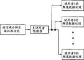
图4表示一种同步或异步CDMA通信用的习知线性多使用者侦测器。来自通信媒体特定接收器的数据输出(如图3所示)被耦合至用以评估个别子频道中的每一被传输符元的脉冲响应的子频道评估器。线性侦测器使用脉冲响应及一子频道评估展开码以解调变每一子频道的数据。此数据被输出至个别使用者的子频道数据处理区块。Figure 4 shows a conventional linear multi-user detector for synchronous or asynchronous CDMA communication. The data output from the communication medium specific receiver (as shown in FIG. 3) is coupled to a subchannel estimator for evaluating the impulse response of each transmitted symbol in the individual subchannel. The linear detector uses the impulse response and a subchannel to estimate the spreading code to demodulate the data for each subchannel. This data is output to the individual user's sub-channel data processing block.
为了在实体系统中作用K子频道使用者的平行侦测,线性多使用者侦测器方法被执行,如同固定的门阵列,微处理器,数字讯号处理器或DSPs及类似者。固定逻辑系统允许较大的系统速度,而微处理器导向系统提供程序化的弹性。负责多使用者侦测器的每一实施执行一连串算术运算。为描述此功能,以下的变量通常定义线性多使用者侦测器的结构及运算:In order to implement parallel detection of K-subchannel users in physical systems, linear multi-user detector methods are implemented, such as fixed gate arrays, microprocessors, digital signal processors or DSPs and the like. Fixed-logic systems allow greater system speed, while microprocessor-oriented systems provide programming flexibility. Each implementation responsible for the multi-user detector performs a series of arithmetic operations. To describe this functionality, the following variables generally define the structure and operation of a linear multiuser detector:
K=系统中主动的使用者/传输器的总数K = total number of active users/transmitters in the system
Nc=一数据区块中的码片数目。码片数目是需要的,因为具有变化的展开因素,此数目对所有使用者是测量的共同点。 Nc = number of chips in a data block. The number of chips is needed because with varying spread factors, this number is common to all users of the measurement.
W=码片中通信频道脉冲响应长度。这通常是系统的预定的参数。W = communication channel impulse response length in chips. This is usually a predetermined parameter of the system.
Q(k)=使用者k的展开因素。此展开因素等于用以展开使用者数据的一符元的码片数目。系统预先知道此展开因素且不需要从接收的数据中评估它们。Q (k) = Expansion factor for user k. The expansion factor is equal to the number of chips used to expand a symbol of user data. The system knows this unfolding factors in advance and does not need to evaluate them from the received data.
Ns(k)=由使用者k所传送的符元数目。Ns(k)=Nc/Q(k)。
d(k)=由使用者k传送的数据(信息)。数据以向量的形式呈现,其中一向量为由一单一索引变量所指示的数据矩阵。为其所遵循的向量及矩阵运算的目的,所有的向量被定义为行向量。d(k)的第nth元素是由kth使用者所传输的nth符元。d (k) = data (message) transmitted by user k. Data is presented in the form of vectors, where a vector is a matrix of data indicated by a single index variable. For the purposes of following vector and matrix operations, all vectors are defined as row vectors. The n th element of d (k) is the n th symbol transmitted by the k th user.
h(k)=被表示为一向量的使用者所经验的子频道的脉冲响应。此量需要在接收器被评估。子频道脉冲响应的接收器评估被称为h(k)。向量的元素h(k)一般是复数个,其具有由子频道导入的振幅及相位变量。h (k) = Impulse response of the sub-channel experienced by the user expressed as a vector. This amount needs to be assessed at the receiver. The receiver estimate of the subchannel impulse response is called h (k) . The elements h (k) of the vector are generally plural, with amplitude and phase variables introduced by the sub-channels.
u(k)=使用者k的展开码,以向量表示。为线性多使用者侦测的目的,考虑包含展开一特定符元的展开码的区段的向量是有用的。因此,向量v(k,n)被定义为用以展开由kth使用者所传送的nth符元的展开码。以数学而言,其被定义为u (k) = unwrapped code of user k, expressed as a vector. For the purpose of linear multi-user detection, it is useful to consider the vector containing the segment of the unwinding code that unwraps a particular symbol. Therefore, a vector v (k,n) is defined as the unwrapping code used to unwrap the n th symbol transmitted by the k th user. Mathematically, it is defined as
vi(k,n)=vi(k),对于(n-1)Q(k)+1#I#nQ(k),以及0对所有其它i,其中i是向量元素的索引。vi (k, n) = vi (k) for (n−1)Q (k) + 1#I#nQ (k) , and 0 for all other i, where i is the index of the vector element.
r(k)=代表使用者k数据,由展开序列v(k)所展开并经由该使者子频道h(k)所传输。向量r(k)代表当一数据区块到达时在周期时间期间的频道观察。r (k) = data representing user k, expanded by the expansion sequence v (k) and transmitted via the messenger sub-channel h (k) . The vector r (k) represents the channel observations during the cycle time when a block of data arrives.
向量r(k)的第ith元素可被定义为The ith element of vector r (k) can be defined as
在接收器所接收的讯号包括所有使用者讯号r(k)加噪声。因此,我们可以定义被接收的数据向量r如下The signal received at the receiver includes all user signals r (k) plus noise. Therefore, we can define the received data vector r as follows
程序2的向量n代表由通信频道所导入的噪声。The vector n of
图5表示习知线性多使用者侦测器的系统及方法。被评估的子频道脉冲响应向量h(k)及展开码v(k)被用以产生每一使用者k的系统传输响应矩阵。一矩阵为由二索引变量所指示的数字区块并且被排列为矩形格,第一索引变量为一列索引,而第二索引变量为一行索引。Figure 5 illustrates a conventional linear multi-user detector system and method. The estimated sub-channel impulse response vector h (k) and the spreading code v (k) are used to generate the system transmission response matrix for each user k. A matrix is a block of numbers indicated by two index variables and is arranged in a rectangular grid, the first index variable being a column index and the second index variable being a row index.
使用者k的系统传输响应矩阵通常被指示为A(k)。第ith列,nth行元素被指示为Ai,n(k)并被定义为The system transmission response matrix for user k is generally denoted A (k) . The i th column, n th row element is denoted as Ai,n (k) and is defined as
矩阵A(k)的每一行对应在想要期间由使用者k所传送的一特定符元用的一匹配的滤波器响应。参照图5,被接收的数据r配合所有使用者展开码与子脉冲响应的组合。因此,A(k)包含Ns(k)匹配的滤波器响应。A(k)的行是以下形式:Each row of matrix A (k) corresponds to a matched filter response for a particular symbol transmitted by user k during the desired period. Referring to FIG. 5, the received data r matches all combinations of user spread codes and sub-impulse responses. Therefore, A (k ) contains Ns (k) matched filter responses. The row of A (k) is of the form:
其中每一向量具有维度where each vector has dimension
Q(k)+W-1 程序5Q (k) +W-1
且从矩阵A(k)的顶部偏移and offset from the top of matrix A (k)
(N-1)·Q(k) 程序6(N-1)·Q (k) Procedure 6
因为展开码在符元时间上不是周期性的;对i,j,bi(k)bj(k)。可能为0值的向量元素被称为向量的支撑。因此,An(k)为bn(k)的支撑。Because the unrolled code is not periodic in symbol time; for i, j, bi (k) bj (k) . A vector element that may have a value of 0 is called the vector's support. Therefore, An (k) is a support for bn (k) .
一旦每一使用者的系统传输矩阵被产生时一全部系统传输响应矩阵,称为A,借由连接所有使用者的系统传输矩阵而被产生,如以下所示:Once the system transfer matrix for each user is generated an overall system transfer response matrix, called A, is generated by concatenating the system transfer matrices of all users as follows:
A=[A(j)...,A(k)...,A(k)] 程序7A=[A (j) ..., A (k) ..., A (k) ] Procedure 7
依据习知的调变技术,h(k)的元素可以是复数个。其随后遵循A的非0元素可以是复数个。According to conventional modulation techniques, elements of h (k) can be plural. It follows that the non-zero elements of A may be plural.
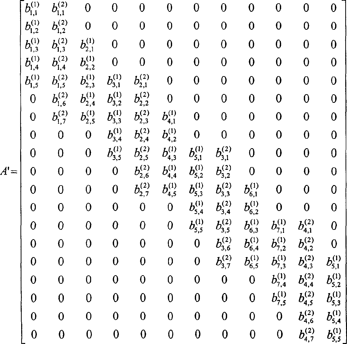
依据程序4,5,6,7的假设的习知侦测器用的全部系统传输响应矩阵的范例为An example of an overall system transmission response matrix for a conventional detector based on the assumptions of

对2位(k=2)使用者,A(1)及A(2),在一数据区块(Nc=16)中具有16码片,长度为4(W=4)的频道脉冲响应以及二的第一位使用者(Q(1)=2)的一展开因素,以及四的第二位使用者(Q(2)=4)的一展开因素。在所产生的全部系统传输响应矩阵A中,bn,i(k)指示组合系统的第ith元素以及第kth使用者的nth符元的频道响应。For 2-bit (k=2) users, A (1) and A (2) , have a channel impulse response of length 4 (W=4) with 16 chips in a data block (Nc=16) and An expansion factor for the first user of two (Q (1) =2), and an expansion factor for the second user of four (Q (2) =4). In the generated overall system transmission response matrix A, bn,i (k) indicates the channel response of the i th element of the combined system and the n th symbol of the k th user.
被接收的数据r使用代表匹配滤波器响应的一排(bank)全部系统传输响应矩阵A被处理以产生匹配滤波器输出的一向量,其以y表示。该匹配的滤波运算被定义为The received data r is processed using a bank of overall system transmission response matrices A representing the matched filter responses to produce a vector of matched filter outputs, denoted by y. The matched filtering operation is defined as
y=AHr 程序9y=A H r Program 9
矩阵AH代表矩阵A的Hermitian(或复数个)转换。该转换被定义为
零强迫区块线性均衡器(ZF-BLE)接收器是具有被指定为O=AHA的一目标矩阵的一线性接收器。最小均方误差区块线性均衡器(MMSE-BLE)接收器是一线性接收器,具有指定为O=AHA+σ2I的目标矩阵,其中σ2为出现在所接收的数据向量r的每一符元上的噪声变化,矩阵I为单位矩阵(identity matrix)。一单位矩阵是一平方及对称矩阵,具有1在其主要对角线以及0在其它地方。单位矩阵的尺寸被选择,因此依据线性代数使得额外的运算有效。A Zero-Forcing Block Linear Equalizer (ZF-BLE) receiver is a linear receiver with an objective matrix designated O=A H A . A Minimum Mean Squared Error Block Linear Equalizer (MMSE-BLE) receiver is a linear receiver with an objective matrix specified as O=A H A+σ 2 I, where σ 2 is present in the received data vector r The noise variation on each symbol of , and the matrix I is an identity matrix. An identity matrix is a square and symmetric matrix with 1s on its main diagonal and 0s elsewhere. The dimensions of the identity matrix are chosen so that additional operations are efficient in terms of linear algebra.
对一解相关器(解相关接收器)而言,矩阵A借由忽略频道响应h(k),仅考虑展开码及它们的交叉相关(干扰)特性而被简化。一交叉相关矩阵通常称为R,一般为了接相关器型态接收器而被建构。此矩阵可借由假设在以上的A的定义中W=1且hi(k)=1而被架构(亦即,每一子频道的频道响应为一脉冲)。随后,交叉相关矩阵R为目标矩阵O,如同为ZF-BLE接收器所定义。一解相关器通常被当成一更复杂多使用者侦测接收器的一次处理使用。一旦目标矩阵产生,多使用者侦测器将逆转此矩阵,标示为O-1。For a decorrelator (decorrelating receiver), the matrix A is simplified by ignoring the channel response h (k) and only considering the spreading codes and their cross-correlation (interference) properties. A cross-correlation matrix, commonly referred to as R, is typically constructed for interfacing with correlator-type receivers. This matrix can be structured by assuming W=1 and hi (k) =1 in the definition of A above (ie, the channel response of each sub-channel is an impulse). Then, the cross-correlation matrix R is the target matrix O, as defined for the ZF-BLE receiver. A decorrelator is usually used as a process in a more complex multi-user detection receiver. Once the target matrix is generated, the MUD will invert this matrix, denoted O -1 .
目标矩阵的逆转随后被乘上匹配的滤波输出向量y以产生数据向量d的评估,其中d(评估)=O-1y。目标矩阵的逆转是一种复杂,计算性的逆转处理。执行此处理所需的运算的数目随矩阵O的尺寸的立方而增加。对大多数不同步CDMA接收器而言,O的尺寸很大,其使得逆转的处理难以实现。The inversion of the target matrix is then multiplied by the matched filtered output vector y to produce an estimate of the data vector d, where d(evaluation) = O −1 y. The inversion of the target matrix is a complex, computational inversion process. The number of operations required to perform this process increases with the cube of the size of matrix O. For most asynchronous CDMA receivers, the size of O is large, which makes the inversion process difficult to implement.
为克服此限制,并使系统实际可靠,由于Cholesky的数字方法被使用。Cholesky分解可以有效地降低矩阵O的计算复杂度,如果矩阵是带状(banded)的话。To overcome this limitation and make the system practically reliable, a numerical method due to Cholesky is used. Cholesky decomposition can effectively reduce the computational complexity of matrix O if the matrix is banded.
一带状矩阵(banded matrix)是一方形矩阵,其仅在远离主要对角的数个对角包括非0值。此接近具有至少一非0元素的主对角的非0对角的数目被称为频宽。因此,一对称矩阵M被称为具有频宽p的带,如果A banded matrix is a square matrix that includes non-zero values only at several diagonals away from the main diagonal. The number of non-zero diagonals close to the main diagonal with at least one non-zero element is called the bandwidth. Therefore, a symmetric matrix M is called a band with bandwidth p if
mij=0,对所有j>i+p 程序10mij=0, for all j>i+p Program 10
其中mij为M的一个元素,i为列索引而j为行索引。对具有尺寸n以及频宽p的带矩阵而言,Cholesky分解可以降低目标矩阵O的所需的逆向数字运算从随着矩阵的尺寸的立方n3变化到随着矩阵的尺寸乘上频宽的平方,np2,变化。where mij is an element of M, i is the column index and j is the row index. For band matrices of size n and bandwidth p, Cholesky decomposition can reduce the required inverse number operations of the target matrix O from as the cube of n 3 the size of the matrix to as the size of the matrix multiplied by the bandwidth Squared, np 2 , varies.
如以上所讨论,ZF-BLE接收器的目标矩阵是O=AHA。为说明数字的复杂度,表示于程序6的整体系统响应矩阵A的目标矩阵为As discussed above, the target matrix for a ZF-BLE receiver is O=A H A. To illustrate the numerical complexity, the objective matrix for the overall system response matrix A expressed in
其中0表示所有算术运算产生0且以x代表非0值。如果整体系统响应矩阵A的第ith列及第jth行的非0元素不具有相同的向量索引,则具有列索引i及行索引j的目标矩阵O的对应元素将是0。O的频宽(程序11)等于9,因为就远离主对角的9行没有非0元素。where 0 means that all arithmetic operations produce 0 and let x represent non-zero values. If the non-zero elements of the ith column and the jth row of the overall system response matrix A do not have the same vector index, then the corresponding element of the target matrix O with column index i and row index j will be 0. The bandwidth of O (program 11) is equal to 9, because the 9 rows just away from the main diagonal have no non-zero elements.
目标矩阵O,如同其于图5所示习知接收器中所架构并未被适当地带化(banded)。因此,Cholesky分解不能有效地被用以降低运算的复杂度,当逆转矩阵O时。然而,习知技术揭露当所有使用者以相等的展开因素传输时,整体系统传输矩阵A的重新排列可以在计算一目标矩阵O,调整矩阵O为一带状矩阵之前先被执行。此处理的系统方块图表示于图6。The object matrix O, as it is structured in the conventional receiver shown in FIG. 5, is not properly banded. Therefore, Cholesky decomposition cannot be effectively used to reduce the complexity of operations when inverting the matrix O. However, the prior art discloses that when all users transmit with equal expansion factors, the rearrangement of the overall system transmission matrix A can be performed before calculating an object matrix O, adjusting the matrix O to a striped matrix. A system block diagram of this process is shown in FIG. 6 .
计算矩阵A的行的重新排列的处理执行重新排列而不需要任何额外的信息。此重新降低排列逆转矩阵时的运算复杂度。一旦侦测程序完成,一使用者数据向量d被计算,一逆转的重新排列处理被执行,解扰乱向量d为进一步处理而回到其原始的形式。The process of computing the rearrangement of the rows of matrix A performs the rearrangement without any additional information. This rearranges the computational complexity when permuting the inversion matrix. Once the detection process is complete, a user data vector d is calculated, a reverse rearrangement process is performed, and the descrambled vector d is returned to its original form for further processing.
在一典型的异步CDMA系统中,一重新排列目标矩阵比其原始尺寸小至少10倍。因此,可达成处理时间中至少100的因素的节省,当Cholesky分解基于一重新排列整体系统响应矩阵而于一目标矩阵上执行的时候。然而,习知技术并未揭露当使用于多主动使用者之间使用不同展开码时所使用的重新排列方法。In a typical asynchronous CDMA system, a rearranged target matrix is at least 10 times smaller than its original size. Thus, a savings of at least a factor of 100 in processing time can be achieved when the Cholesky decomposition is performed on a target matrix based on a rearranged global system response matrix. However, the prior art does not disclose the rearrangement method used when different unwrapping codes are used among multiple active users.
因此,希望降低多使用者侦测的复杂度。Therefore, it is desirable to reduce the complexity of multi-user detection.
发明内容Contents of the invention
复数个通信讯号具有不同的展开码。每一通信具有包括码片的一相关的码。为每一通信的每一码片,产生以一脉冲响应回旋(convolved)的码片的向量。为每一通信,产生包括码片向量的支撑区块。一支撑区块中的码片向量的数目是基于该通信的展开因素。一系统响应矩阵被组合。该系统响应矩阵具有符元次矩阵。每一符元次矩阵包括来自每一通信的一支撑区块。该通信的数据使用该符元矩阵而被侦测。The plurality of communication signals have different spreading codes. Each communication has an associated code comprising chips. For each chip of each communication, a vector of chips convolved with an impulse response is generated. For each communication, a strut block including chip vectors is generated. The number of chip vectors in a strut block is based on the spread factor of the communication. A system response matrix is assembled. The system response matrix has a symbolic submatrix. Each symbol sub-matrix includes a supporting block from each communication. The communicated data is detected using the symbol matrix.
附图说明Description of drawings
图1是习知多重存取通信系统的简要方块图。FIG. 1 is a schematic block diagram of a conventional multiple access communication system.
图2是习知CDMA通信系统中简要方块图。Fig. 2 is a schematic block diagram of a conventional CDMA communication system.
图3是习知具多使用者侦测的CDMA接收器的简要方块图。FIG. 3 is a schematic block diagram of a conventional CDMA receiver with multi-user detection.
图4是习知多使用者侦测器的简要方块图。FIG. 4 is a schematic block diagram of a conventional multi-user detector.
图5是习知线性多使用者侦测器的方块图。FIG. 5 is a block diagram of a conventional linear multi-user detector.
图6是习知使用Cholesky分解的线性多使用者侦测器的方块图。FIG. 6 is a block diagram of a conventional linear multi-user detector using Cholesky decomposition.
图7是本发明线性多使用者侦测器的方块图。Fig. 7 is a block diagram of the linear multi-user detector of the present invention.
图8说明系统响应矩阵A(k)上至下行偏移。FIG. 8 illustrates the system response matrix A (k) uplink to downlink offset.
图9说明矩阵行索引值分派。Figure 9 illustrates matrix row index value assignment.
图10A及10B是实施本发明的另一方法的流程图。10A and 10B are flowcharts of another method of implementing the present invention.
图11说明组合一展开因素群矩阵AG(g)的步骤。Fig. 11 illustrates the steps of assembling an expanded factor group matrix AG (g) .
图12说明依据本发明组合一AN矩阵的步骤。Figure 12 illustrates the steps of assembling an AN matrix according to the present invention.
图13说明一系统响应矩阵的另一组合。Figure 13 illustrates another combination of a system response matrix.
图14说明一kth资源单位的系统响应矩阵,Ak。Figure 14 illustrates the system response matrix, Ak, for a k th resource unit.
图15说明一kth资源单位的第一支撑区块,B(1,k)。FIG. 15 illustrates the first supporting block, B (1,k) of a k th resource unit.
图16说明组合另一系统响应矩阵A的步骤。Fig. 16 illustrates the steps of combining another system response matrix A.
具体实施方式Detailed ways
实施例将参照附图而被描述,其中相同的数字代表相同的组件。Embodiments will be described with reference to the drawings, wherein like numerals represent like components.
表示于图7的是于接收之后侦测复数个在共同CDMA频道中传输的使用者的多使用者侦测器17。该多使用者侦测器17包括复数个具有附属存储器的用以执行各种向量及矩阵运算的处理器。另一实施例包括固定的门阵列及执行该不同处理器功能的DSPs。侦测器17也包含第一输入19用以输入被称为向量h(k)的个别的k子频道脉冲响应评估至正确的中间符元干扰或由一子频道本身符元所导致的ISI以及多重存取干扰或由来自其它使用者子频道的符元所倒致的所有接收数据讯号的MAI,一第二输入21用以输入来自所有在不连续区块时间内传输的所有使用者k的包含来自每一使用者资频道的组合数据的输入向量r的形式的数据,以及一输出23用以输出每一使用者k的来自被接收频道数据r的一输出向量形式的使用者数据d(k)。使用者K及每一使用者(k=1,2,3,...K)的展开因素Q(k)41为已知。Shown in FIG. 7 is a multi-user detector 17 that detects a plurality of users transmitting in a common CDMA channel after reception. The multi-user detector 17 includes a plurality of processors with attached memory for performing various vector and matrix operations. Another embodiment includes fixed gate arrays and DSPs that perform the various processor functions. The detector 17 also includes a first input 19 for inputting individual k subchannel impulse response estimates called vector h (k) to correct intersymbol interference or ISI due to a subchannel's own symbols and Multiple access interference or MAI of all received data signals caused by symbols from other user sub-channels, a
为获得来自组合的使用者数据r的一特定使用者的使用者数据d(k),使用者数据必须使用匹配滤波器25或类似者来过滤。熟悉本技术的人士认可一匹配滤波器25需要一响应特征,其为展开脉冲形状与使用者子频道脉冲响应的组合的复数个共轭,以便产生具有代表传输前的讯号准位的输出。输入没有与一预定响应特征匹配的滤波器25的讯号产生一较低的输出。In order to obtain the user data d (k) of a specific user from the combined user data r, the user data must be filtered using a matched filter 25 or similar. Those skilled in the art will recognize that a matched filter 25 requires a response characteristic that is the complex conjugate of the combination of the expanded pulse shape and the user sub-channel impulse response in order to produce an output having a signal level representative of that prior to transmission. Signals input to filter 25 that do not match a predetermined response characteristic produce a lower output.
每一独立的k子频道脉冲响应评估h(k)被输入一第一存储器27,于该处与产生该使用者的系统传输响应评估矩阵A(k)的相同的使用者展开码29(程序3)组合。多使用者侦测器17的一排列处理器33执行所有矩阵An(k)行的重新排序。此排列方法需要每一子频道系统传输响应矩阵A(k)具有由程序4所定义的行结构,其为典型的线性接收器。如果系统响应矩阵A(k)不是由程序4所定义的形式,排列处理器33首先重新安排在些行为程序4所定义的结构。多使用者侦测器17不需要所有系统传输响应矩阵A(k)被串连为如程序7所定义的一整体系统传输响应矩阵A。Each individual k subchannel impulse response estimate h (k) is input into a first memory 27 where the same user spread code 29 (program 3) Combination. An alignment processor 33 of the multi-user detector 17 performs the reordering of all rows of the matrix An (k) . This arrangement method requires that each sub-channel system transmission response matrix A (k) has a row structure defined by procedure 4, which is a typical linear receiver. If the system response matrix A (k) is not in the form defined by program 4, the arrangement processor 33 first rearranges the structure defined by program 4 in these rows. The multi-user detector 17 does not require all system transmission response matrices A (k) to be concatenated into an overall system transmission response matrix A as defined in procedure 7.
排列器33为来自定义上O(k)Tn及下O(k)Bn偏移的每一向量(程序4)的支撑的零值元素检查每一系统传输矩阵A(1),A(2),A(3),...A(k)。如前所述,每一系统传输响应矩阵A(k)具有相同的列数目;只有行数目变化。如图9所示,此排列处理器33基于其个别的上O(k)Tn及下O(k)Bn效应为每一系统传输响应矩阵A(k)的每一行指派一索引值ni。此行值以增加的大小的次序从具有最大下偏移(offset)的最小上偏移的行被指派至具有最小下偏移的最大上偏移的行。Arranger 33 examines each system transfer matrix A (1) , A (2) for the zero-valued elements of the support from each vector (Procedure 4) offset by O (k) Tn above and O (k)Bn below O(k) Bn , A (3) ,...A (k) . As before, each system transmission response matrix A (k) has the same number of columns; only the number of rows varies. As shown in FIG. 9 , the permutation processor 33 assigns an index value ni to each row of the transmission response matrix A (k) for each system based on its respective upper O (k) Tn and lower O (k) Bn effects. The row values are assigned in order of increasing size from the row with the smallest upper offset with the largest lower offset (offset) to the row with the largest upper offset with the smallest lower offset.
如果二行遭遇一者具有较大的上偏移以及比另一者大的下偏移,如果上偏移之间的差异大于下偏移之间的差异,具较下方的上偏移的行被指派较低的索引ni。如果下偏移之间的差异大于上偏移之间的差异,具有较大下偏移的行被指派较低的索引ni。如果上偏移与下偏移之间的差异相同,二行中的一者可以被指派较低的索引ni。If two rows encounter one with a larger upper offset and a larger lower offset than the other, the row with the lower upper offset if the difference between the upper offsets is greater than the difference between the lower offsets is assigned the lower index ni. If the difference between the lower offsets is greater than the difference between the upper offsets, the row with the larger lower offset is assigned a lower index ni. If the difference between the upper and lower offsets is the same, one of the two rows may be assigned a lower index ni.
排列处理器33组合一整体系统传输响应矩阵AN为被指派的行索引ni的次序。此行索引ni被维持在存储器33中以便在解扰乱处理45期间使用。举例而言,使用程序8所示的整体系统响应矩阵A(1)及A(2),本发明排列方法17产生如下所述的整体系统传输矩阵A:The permutation processor 33 assembles an overall system transmission response matrix AN into the order of the assigned row indices ni. This row index ni is maintained in memory 33 for use during the descrambling process 45 . For example, using the overall system response matrices A (1) and A (2) shown in Procedure 8, the permutation method 17 of the present invention generates the overall system transmission matrix A as follows:
此排列方法指示系统传输响应矩阵A(1)的8行(1-8)及系统传输响应矩阵A(2)的四行(9-12)以产生一良好带化的整体系统传输矩阵A(程序12)。This arrangement indicates eight rows (1-8) of the system transmission response matrix A (1) and four rows (9-12) of the system transmission response matrix A (2) to produce a well-banded overall system transmission matrix A( Procedure 12).
以上所述的排列的方法实施例包括每一系统传输响应矩阵A(1),A(2),A(3)...A(k)的检查,比较每一行与每一其它行的上O(k)Tn及下O(k)Bn偏移。假定每一系统传输响应矩阵A(k)的特定结构,亦即,每一矩阵的行被排列为增加的上偏移及下降的下偏移的次序,当从左至右前进时(参照程序8,矩阵A(1),A(2)),另一方法199可以被执行而不需要直接检查每一系统传输响应矩阵A(k)。The permutation method embodiment described above includes inspection of each system transmission response matrix A (1) , A (2) , A (3) ... A (k) , comparing each row with the upper O (k) Tn and lower O (k) Bn offset. Assume a specific structure for each system transmission response matrix A (k) , i.e., the rows of each matrix are arranged in order of increasing upper offset and decreasing lower offset, when proceeding from left to right (cf. 8. Matrices A (1) , A (2) ), another method 199 can be performed without directly checking each system transmission response matrix A (k) .
另一方法199表示在图10A及10B。所有对应(步骤201)具有相等展开因素的使用者的系统传输响应矩阵A(k)被群集在一起(步骤203)。对每一展开因素群g,存储器被配置于处理器内能够储存来自所有系统传输矩阵A(1),A(2),A(3)...A(k)的所有行。展开因素群g被排列为增加的展开因素的次序。Another method 199 is shown in Figures 10A and 10B. All system transmission response matrices A (k) corresponding to (step 201 ) users with equal spread factors are clustered together (step 203 ). For each expansion factor group g, a memory is configured in the processor capable of storing all rows from all system transfer matrices A (1) , A (2) , A (3) . . . A (k) . The expansion factor group g is arranged in order of increasing expansion factors.
说明该另一方法199的性能的例示系统包含7个具有4个被指派如下的不同展开因素Q(k):An exemplary system illustrating the performance of this alternative method 199 contains 7 different expansion factors Q (k) with 4 assigned as follows:
使用者1(Q(1))=8 使用者2(Q(1))=8 使用者3(Q(3))=8 使用者4(Q(4))=32User 1 (Q (1) ) = 8 User 2 (Q (1) ) = 8 User 3 (Q (3) ) = 8 User 4 (Q (4) ) = 32
使用者5(Q(5))=16 使用者6(Q(6))=16 使用者7(Q(7))=4User 5(Q (5) )=16 User 6(Q (6) )=16 User 7(Q (7) )=4
使用另一方法的系统及方法199,系统传输响应矩阵A(k)被分离为展开因素群:Using another method of systems and methods 199, the system transmission response matrix A (k) is separated into groups of expansion factors:
群1(展开因素4)A(7) Group 1 (expansion factor 4)A (7)
群2(展开因素8)A(1),A(2),A(3) Group 2 (expansion factor 8) A (1) , A (2) , A (3)
群3(展开因素16)A(5),A(6) Group 3 (expansion factor 16) A (5) , A (6)
群4(展开因素32)A(4) Group 4 (expansion factor 32)A (4)
一个别的展开因素群g包括至少一系统传输矩阵A(k),其中每一矩阵A(k)是从1至L(g)的任意索引。每一展开因素群g依据增加的展开因素大小被索引。An individual expansion factor group g includes at least one system transmission matrix A (k) , where each matrix A (k) is an arbitrary index from 1 to L (g) . Each expansion factor group g is indexed in terms of increasing expansion factor size.
再每一展开因素群中,相关系统传输响应矩阵A(k)被组合为共同展开因素群传输响应矩阵AG(g),其中g=1,2,3,...G(步骤205)。如图11所示,方法199复制具有索引1的系统传输响应矩阵的第一行至AG(g)的第一空白行,具有索引2的系统传输响应矩阵的第一行至AG(g)的第二空白行;在个别的展开因素群g中继续贯辙剩下的系统传输响应矩阵直到所有的第一行被复制为止。方法199以复制个别展开因素群AG(g)中的每一矩阵A(k)的第二行,第三行等等而进行。In each expanded factor group, the related system transmission response matrix A (k) is combined into a common expanded factor group transmission response matrix AG (g) , where g=1, 2, 3, . . . G (step 205 ). As shown in FIG. 11 , method 199 copies the first row of the system transmission response matrix with
展开因素群g中的所有矩阵由于相同的展开因素而具有相同的行数。因此,组合的展开群因素群传输响应矩阵AG(g)将具有相关系统传输响应矩阵A(k)中的行数的L(g)倍。All matrices in the expansion factor group g have the same number of rows due to the same expansion factor. Thus, the combined expanded group factor group transmission response matrix AG (g) will have L (g) times the number of rows in the associated system transmission response matrix A (k) .
为组合配合变化的展开因素的一整体系统传输响应矩阵AN,具有最低展开因素的展开群因素群传输响应矩阵AG(g)被连续复制到存储器内(步骤207),以第一行开始,亦即,AG(g)的第一行,至AN的第一配置的行。具有最低展开因素的展开群因素群传输响应矩阵AG(g)具有最大的行数目。所有其它的展开群因素群传输响应矩阵将被插入此基础矩阵AN。To assemble an overall system transmission response matrix AN with varying expansion factors, the expansion group factor group transmission response matrix AG (g) with the lowest expansion factor is successively copied into memory (step 207), starting with the first row, i.e. That is, the first row of AG (g) , to the first configured row of AN. The expanded group factor group transmission response matrix AG (g) with the lowest expanded factor has the largest number of rows. All other expanded group factor group transmission response matrices will be inserted into this fundamental matrix AN.
如果系统展开因素是其它的偶数整数倍(步骤209),处理器33借由考虑剩下的展开群因素群传输响应矩阵AG(g)(步骤209)以任意次序组合该整体系统传输矩阵AN(步骤211)。为每一展开群因素群传输响应矩阵AG(g),处理器33驱动一行位移参考索引m,If the system expansion factor is other even integer multiples (step 209), the processor 33 combines the overall system transmission matrix AN( Step 211). For each expanded group factor group transfer response matrix AG (g) , processor 33 drives a row of displacement reference index m,
其中表示与在考虑中的展开群因素群传输响应矩阵AG(g)相关的展开因素,Q(1)表示所有群中最低的展开码,n是在考虑中的展开群因素群传输响应矩阵AG(g)的行,其中n=1,2,3,....N(步骤211)。where denotes the expansion factor associated with the expansion group factor group transmission response matrix AG (g) under consideration, Q (1) denotes the lowest expansion code among all groups, and n is the expansion group factor group transmission response matrix AG under consideration Lines of (g) , where n=1, 2, 3, ... N (step 211).
为使用行位移索引m,使用建立具有最低展开因素的展开群因素群传输响应矩阵的系统传输响应矩阵L(1)的全部数目导出AN中的一参考位置(步骤215),To use the row displacement index m, a reference position in AN is derived using the total number of system transmission response matrices L (1) that create the expanded group factor group transmission response matrix with the lowest expansion factor (step 215),
mHL(1) 程序14mHL (1) Program 14
处理器33在考虑下,使用属于目前在考虑中的展开因素群的系统传输响应矩阵从展开群因素群传输响应矩阵AG(g)导出一行集合(步骤217),Processor 33, under consideration, derives a set of rows from the expanded group factor group transmission response matrix AG (g) using the system transmission response matrix belonging to the expanded factor group currently under consideration (step 217),
L(g)H(n-1)+1至L(g)Hn 程序15L (g) H(n-1)+1 to L (g) Hn Program 15
处理器33从AG(g)复制由程序15定义的行集合并将其插入具有由程序14定义的参考位置的AG(1)的行之后的基础矩阵AN,如图12所示。在考虑中的展开因素群矩阵的剩下的行同样地被复制并插入基础矩阵AN(步骤211)。在所有来自一展开因素群矩阵的行都被取代之后,处理器33选择下一展开因素群矩阵AG(g)(步骤223)并执行以上方法。程序13,14,15允许来自剩下的展开群因素群传输响应矩阵AG(g)的第ith行被放置在AN中具有相似支撑的mth行之后(步骤225)。Processor 33 copies the set of rows defined by program 15 from AG (g) and inserts them into the fundamental matrix AN after the rows of AG (1) with reference positions defined by program 14, as shown in FIG. 12 . The remaining rows of the expanded factor group matrix under consideration are likewise copied and inserted into the fundamental matrix AN (step 211). After all rows from an expanded factor group matrix have been replaced, processor 33 selects the next expanded factor group matrix AG (g) (step 223 ) and executes the above method. Procedures 13, 14, 15 allow the i th row from the remaining expanded group factor group transmission response matrix AG (g) to be placed after the m th row in AN with similar support (step 225).
当系统展开因素不是其它的偶整数倍时,程序13的右边表示不产生一整数。在此情况中,处理器33将使程序13的结果近似以上的最接近整数或该数值以下的最接近整数(步骤213)。此近似值方向在整体系统性能上具有可忽略的效果。剩余群系统传输矩阵AG(g)考虑的次序可能对系统性能有些影响。习知的展开因素的知识可被用以预先选择适合的次序。When the system expansion factor is not other even integer multiples, the right side of program 13 does not generate an integer. In this case, processor 33 will round the result of program 13 to the nearest integer above or to the nearest integer below that value (step 213). This approximation direction has negligible effect on overall system performance. The order in which the transfer matrix AG (g) of the residual group system is considered may have some influence on the system performance. Knowledge of known expansion factors can be used to preselect the appropriate order.
使用以上所述的排列技术,以及为了当展开因素是互相的偶整数倍的情况,一矩阵频宽B可被达成,其可被表示为:Using the permutation techniques described above, and for the case when the expansion factors are even multiples of each other, a matrix bandwidth B can be achieved, which can be expressed as:
程序16预言程序11的整体系统传输响应矩阵的频宽将是3及6。程序12的检查显露在每一排列方法199之后的频宽是4。
此改善在传输的符元的数目增加时更明显。如果系统传输第一使用者的16000码片(第一使用者的800符元以及第二使用者的400符元),矩阵AHA的频宽将大约是800。使用此排列方法以产生一整体系统响应矩阵A,ANHAN的频宽维持4,因为频宽(程序16)是独立于被传输符元的数目。在所有目标矩阵O的元素都被导出之后,执行逆转41。因为逆转一矩阵的复杂度与频宽的平方成比例,本发明17提供近似(800/4)2=2002=40000的因素的计算复杂度的降低。This improvement is more pronounced as the number of symbols transmitted increases. If the system transmits 16000 chips for the first user (800 symbols for the first user and 400 symbols for the second user), the bandwidth of the matrix A H A will be about 800. Using this permutation method to generate an overall system response matrix A, the bandwidth of AN H AN remains 4 because the bandwidth (procedure 16) is independent of the number of transmitted symbols. After all elements of the target matrix O have been derived, inversion 41 is performed. Since the complexity of inverting a matrix scales with the square of the bandwidth, the present invention 17 provides a reduction in computational complexity by a factor of approximately (800/4) 2 =200 2 =40000.
整体系统传输响应矩阵AN提供响应特征给匹配的滤波器25。系统响应矩阵AN的每一行是代表一特定符元的响应特征的向量。被接收的数据向量r被输入匹配滤波器25,其中,其与来自整体系统传输响应矩阵AN的每一响应特征匹配以产生一匹配的滤波器输出向量y。输出向量y的每一元素对应由一预定使用者传输的一特定符元的初步的评估。来自匹配滤波器25的输出向量y被加载具有逆转目标矩阵O的一乘法器43。匹配滤波器25输出向量y及逆转目标矩阵O二者被相乘以产生一使用者数据向量d。使用者数据向量d包含在不连续时间区块期间从所有使用者传输的所有数据。因为目标矩阵O及匹配滤波器25输出是以整体系统响应矩阵AN为基础,使用者数据向量d必需被解扰乱。此解扰乱程序是排列方法199的逆转。The overall system transmission response matrix AN provides the response characteristics to the matched filter 25 . Each row of the system response matrix AN is a vector representing the response characteristic of a particular symbol. The received data vector r is input to a matched filter 25 where it is matched with each response signature from the overall system transmission response matrix AN to produce a matched filter output vector y. Each element of the output vector y corresponds to a preliminary evaluation of a particular symbol transmitted by an intended user. The output vector y from the matched filter 25 is loaded into a multiplier 43 with an inverted object matrix O. The output vector y of the matched filter 25 and the inverted target matrix O are multiplied to generate a user data vector d. User data vector d contains all data transmitted from all users during discrete time blocks. Since the target matrix O and the matched filter 25 output are based on the overall system response matrix AN, the user data vector d must be descrambled. This descrambling procedure is the reverse of permutation method 199.
一解扰乱器45基于执行的行重新排列而重新安排使用者数据向量d的每一元素,当经历排列方法199时。数据向量d的元素是处于由整体传输响应矩阵A,1,9,2,3,10,4,5,11,6,7,12,8所指示的相同次序,垂直移项(transposed vertically)。解扰乱器45配置具有相同尺寸的存储器空间并将每一向量元素放置为1-12的连续次序。在使用者数据向量d被解扰乱之后,使用者数据被输出23以便进一步处理。A descrambler 45 rearranges each element of the user data vector d when subjected to the permutation method 199 based on the row rearrangement performed. The elements of the data vector d are in the same order indicated by the overall transmission response matrix A, 1, 9, 2, 3, 10, 4, 5, 11, 6, 7, 12, 8, transposed vertically . The descrambler 45 configures the memory space with the same size and places each vector element in a consecutive order of 1-12. After the user data vector d is descrambled, the user data is output 23 for further processing.
另一种降低系统传输响应矩阵A的频宽的方法表示于图13,图14及图15,并且比图6的流程图被解释。图13说明符元响应矩阵A。A矩阵被设置因此有S符元次矩阵。S为符元的最小数目,因此系统中的一资源单元的一数据区域可具有S=Nc/QMAX。Nc为数据区域中的码片数目。QMAX为系统的最大展开因素,例如一展开因素16。为说明分时双工爆冲型态2,Nc为1104而一典型的最大延迟展开QMAX为16。因此,A矩阵包含69(Nc/QMAX)次矩阵。Another method of reducing the bandwidth of the system transmission response matrix A is shown in FIG. 13 , FIG. 14 and FIG. 15 , and explained compared to the flow chart of FIG. 6 . Figure 13 illustrates the symbol response matrix A. A matrix is set up so that there are S symbol sub-matrixes. S is the minimum number of symbols, so a data region of a resource unit in the system may have S=N c /Q MAX . N c is the number of chips in the data region. Q MAX is the maximum expansion factor of the system, for example, an expansion factor of 16 . To illustrate TDD burst
每一次矩阵具有K被接收资源单位的每一者的一支撑区块B(s,k)。s代表从1至S的符元次矩阵,而k代表来1至K的资源单位数目。Each sub-matrix has a supporting block B (s,k) for each of the K received resource units. s represents the sub-matrix of symbols from 1 to S, and k represents the number of resource units from 1 to K.
对每一资源单位,一系统响应矩阵可被建立。此矩阵具有资源单元的每一符元一行,Nc/Qk行。Qk是第kth资源单位展开因素。每一行具有一ith行的一行区块b(k,i)。每一区块具有一行长度为该资源单位符元脉冲响应长度Lr加上1,Lr+1。对矩阵的第一区块B(k,1)(最左),区块的上部是矩阵的上部。每一次区块为一符元,Qk,矩阵中的较低者。为说明,第二行b(k,2)的行区块是矩阵中低于b(k,1)的Qk码片。For each resource unit, a system response matrix can be built. This matrix has one row for each symbol of the resource unit, N c /Q k rows. Q k is the kth resource unit expansion factor. Each row has a row of blocks b (k,i) for an i th row. Each block has a row length equal to the resource unit symbol impulse response length L r plus 1, L r +1. For the first block B (k,1) of the matrix (far left), the upper part of the block is the upper part of the matrix. Each block is one symbol, Q k , the lower of the matrix. To illustrate, the row blocks of the second row b (k,2) are the Q k chips below b (k,1) in the matrix.
每一行区块b(k,i)对应第kth资源单元的一ith符元。其是借由扰乱码的第ith区段与用该区段的频道脉冲响应回旋的第kth资源单位的码片接码片地相乘而被导出,如程序17,步骤300。Each row of blocks b (k, i) corresponds to an i th symbol of the k th resource unit. It is derived by chip-by-chip multiplication of the i th segment of the scrambling code with the k th resource unit convolved with the channel impulse response of the segment, as in procedure 17, step 300 .
c(k,i)为第kth码的第ith区段。cscram(k,i)为扰乱码的第ith区段。h(k)为第kth资源单元的频道响应。因此,第kth资源单位的每一行区块的长度为Qk+Lr-1。c (k, i) is the i th segment of the k th code. cscram (k, i) is the ith segment of the scrambling code. h (k) is the channel response of the k th resource unit. Therefore, the length of each row of blocks in the k th resource unit is Qk+Lr-1.
资源单元系统响应矩阵A1至Ak的行区块被用以产生图13的符元次矩阵的支撑区块。图十五说明第一符元区块中一kth资源单元的一支撑区块B(k,1)。支撑区块B(k,1)具有行QMAX/Qk。为说明,如果系统的最大展开因素为16(QMAX=16)且资源单元的展开因素为1(Qk=1),支撑区块B(k,1)具有16行。相反地,如果资源单元展开因素为16,支撑区块B(k,1)具有1行。The row blocks of the resource unit system response matrices A1 to Ak are used to generate the support blocks of the symbol sub-matrix of FIG. 13 . FIG. 15 illustrates a supporting block B (k, 1) of a k th resource unit in the first symbol block. Support block B (k,1) has row Q MAX /Q k . To illustrate, if the maximum expansion factor of the system is 16 (Q MAX =16) and the expansion factor of resource units is 1 (Q k =1), the strut block B (k, 1) has 16 rows. Conversely, if the resource unit expansion factor is 16, the supporting block B (k, 1) has 1 row.
为来自一kth资源单元的第一支撑区块,该资源单元系统响应矩阵Ak的第一行区块QMAX/Qk被取得。支撑区块的第一行具有系统响应矩阵K的第一区块行。支撑区块中的第一区块行的上部是位于支撑区块的上部。所产生的支撑区块的整体高度为QMAX+Lr-1,不管展开因素Qk,步骤302。For the first supporting block from a k th resource unit, the block Q MAX /Q k of the first row of the system response matrix Ak of the resource unit is obtained. The first row of the support block has the first block row of the system response matrix K. The upper part of the first block row in the supporting block is located on the upper part of the supporting block. The overall height of the resulting support block is Q MAX +L r −1 regardless of the expansion factor Qk, step 302 .
图13表示符元次矩阵B(a,k)中的支撑区块。每一符元次矩阵,具有每一资源单位的一sth支撑区块B(s,k),步骤304。或者是,行区块b(k,i)可从Ak矩阵获得或直接插入符元次矩阵B(s,k)。支撑区块的每一区块行b(k,i)是从该资源单元Ak矩阵的一区块行获得。来自一符元次区块的矩阵的行是b(k,x+1)至b(k,x+QMAX/QK)。x来自程序18。FIG. 13 shows the supporting blocks in the symbol sub-matrix B (a,k) . Each symbol sub-matrix has an s th supporting block B (s, k) for each resource unit, step 304 . Alternatively, the row block b (k, i) can be obtained from the matrix A k or directly inserted into the sub-matrix B (s, k) . Each block row b (k, i) of a supporting block is obtained from a block row of the resource element A k matrix. The rows of the matrix from the one-symbol block are b (k,x+1) to b (k,x+QMAX/QK) . x comes from program 18.
X=(s-1)*QMAX/Qk 程序18X=(s-1)*Q MAX /Q k Program 18
为一特定的资源单元k,每一次区块包含该资源单元行区块的QMAX/Qk。支撑区块中的第一行的上部在支撑区块的上部。每一后续行是支撑区块中较低的QMAX/Qk码片。For a specific resource unit k, each sub-block contains Q MAX /Q k of the resource unit row block. The upper part of the first row in the support block is on the upper part of the support block. Each subsequent row is the lower Q MAX /Q k chip in the supporting block.
如图13所示,每一符元次区块具有每一资源单元用的支撑区块B(s,k)。虽然资源单元可被设置为任意次序且依然达成降低的频宽,借由放置以较低展开因素传输的资源单元在每一次矩阵区块的外部,频宽可以被进一步降低。为说明,第一次矩阵的第一支撑的第一行区块为Lr。如果展开因素为16(Q1=16),第一行区块的长度为15+Lr。这些额外的15码片增加整体的频宽。以最后次矩阵的最后支撑的最后行,这依然为真。然而,在某些实施中,频宽中的潜在降低可能不会比重新排列资源单元次序用的增加复杂度重要。As shown in FIG. 13, each symbol sub-block has a supporting block B (s, k) for each resource unit. Although RUs can be arranged in any order and still achieve reduced bandwidth, bandwidth can be further reduced by placing RUs transmitted with lower spreading factors outside each matrix block. For illustration, the block in the first row of the first support of the first matrix is Lr. If the expansion factor is 16 (Q 1 =16), the length of the first row of blocks is 15+Lr. These extra 15 chips increase the overall bandwidth. This remains true with the last row of the last support of the last matrix. However, in some implementations, the potential reduction in bandwidth may not outweigh the added complexity of rearranging the resource unit order.
Sth符元次矩阵具有每一资源单元用的一支撑区块,步骤304。因为每一支撑区块具有相同的高度,每一次矩阵具有QMAX+Lr-1码片的相同高度每一次矩阵的宽度为M,如程序19。The S th symbol sub-matrix has a supporting block for each resource unit, step 304 . Since each strut block has the same height, each sub-matrix has the same height of Q MAX +Lr-1 chips and the width of each sub-matrix is M, as in procedure 19.
第一符元次矩阵是位于系统响应矩阵A的上方右角落。每一后续矩阵沿前一矩阵的侧边且QMAX码片进一步下降。A矩阵的整体高度是Ns*QMAX+Lr-1,而整体宽度为M*Ns。如图13所示,A矩阵的结构大量降低频宽。此外,在导出此降低的频宽A矩阵的复杂度是小的。The first symbolic matrix is located in the upper right corner of the system response matrix A. Each subsequent matrix falls further along the side of the previous matrix and QMAX chips. The overall height of the A matrix is N s *Q MAX + Lr −1, and the overall width is M*N s . As shown in Figure 13, the structure of the A-matrix greatly reduces the bandwidth. Furthermore, the complexity in deriving this reduced bandwidth A-matrix is small.
在实际的通信站中,由于果度取样及传输或接收差异,A矩阵可以包括数个次矩阵。在使用者设备或在基地台的接收器可以对所接收的向量r取样,以多重码片速率,例如在二或四倍码片速率。此外,可以使用传输或接收差异。对一个使用过度取样及传输/接收差异的系统,A矩阵可以被视为具有来自过度取样及来自该差异的样本的每一组合的一次矩阵。为说明,一接收器可以在产生偶及奇样本的二倍码片速率取样。此接收器也可以在二空间差异天线。天线1及天线2,接收讯号。因此,一偶集合在天线2而一奇集合在天线1,一奇集合在天线1,一偶集合在天线2以及一奇集合在天线2。于此情况中,被接收的讯号可以如程序20所述的模式。In an actual communication station, the A matrix may include several sub-matrices due to degree sampling and transmission or reception differences. A receiver at the UE or at the base station may sample the received vector r at multiple chip rates, for example at double or quadruple the chip rate. Also, transmit or receive diffs can be used. For a system using oversampling and transmit/receive disparity, the A matrix can be viewed as having a primary matrix for each combination of samples from oversampling and from the disparity. To illustrate, a receiver may sample at twice the chip rate to generate even and odd samples. This receiver can also work on two spatially differentiated antennas.
A10对应天线1及偶样本。A1,S对应至天线1及奇样本。A2,e对应天线2及偶样本。A 10 corresponds to
在一般情况中,其中多重码片速率取样被使用并使用n天线,A可由程序21形成。In the general case, where multiple chip rate sampling is used and n antennas are used, A can be formed by
为降低A矩阵的频宽,每一次矩阵具有其由一种降低频宽的技术所降低的频宽。当A矩阵被使用于数据侦测方法中时,每一次矩阵的降低的频宽降低A矩阵的频宽。To reduce the bandwidth of the A matrix, each sub-matrix has its bandwidth reduced by a bandwidth reduction technique. When the A-matrix is used in the data detection method, each time the bandwidth of the matrix is reduced reduces the bandwidth of the A-matrix.
虽然本发明已使用较佳实施例而为说明,已于以下申请专利范围中所指出的本发明范围内的变化对本技术领域的人士而言是很明显的。While the invention has been described using preferred embodiments, variations within the scope of the invention which are indicated in the following claims will become apparent to those skilled in the art.
Claims (40)
Applications Claiming Priority (3)
| Application Number | Priority Date | Filing Date | Title |
|---|---|---|---|
| US10/174,121 | 2002-06-18 | ||
| US10/174,121 US6714527B2 (en) | 1999-09-21 | 2002-06-18 | Multiuser detector for variable spreading factors |
| PCT/US2003/018438 WO2003107688A2 (en) | 2002-06-18 | 2003-06-11 | Multiuser detector for variable spreading factors |
Publications (2)
| Publication Number | Publication Date |
|---|---|
| CN1663160A true CN1663160A (en) | 2005-08-31 |
| CN1663160B CN1663160B (en) | 2013-01-02 |
Family
ID=29733502
Family Applications (1)
| Application Number | Title | Priority Date | Filing Date |
|---|---|---|---|
| CN038143089A Expired - Fee Related CN1663160B (en) | 2002-06-18 | 2003-06-11 | Multiuser detector for variable spreading factors |
Country Status (11)
| Country | Link |
|---|---|
| US (3) | US6714527B2 (en) |
| EP (1) | EP1525696B1 (en) |
| JP (1) | JP4083740B2 (en) |
| KR (2) | KR100630861B1 (en) |
| CN (1) | CN1663160B (en) |
| AT (1) | ATE335324T1 (en) |
| AU (1) | AU2003248665A1 (en) |
| DE (1) | DE60307282T2 (en) |
| ES (1) | ES2270098T3 (en) |
| TW (3) | TWI342680B (en) |
| WO (1) | WO2003107688A2 (en) |
Families Citing this family (30)
| Publication number | Priority date | Publication date | Assignee | Title |
|---|---|---|---|---|
| JP4557331B2 (en) * | 1999-05-20 | 2010-10-06 | キヤノン株式会社 | Information processing apparatus, information processing system, operation control method, and computer-readable recording medium |
| US6714527B2 (en) * | 1999-09-21 | 2004-03-30 | Interdigital Techology Corporation | Multiuser detector for variable spreading factors |
| KR20050039883A (en) * | 1999-09-21 | 2005-04-29 | 인터디지탈 테크날러지 코포레이션 | Multiuser detector for variable spreading factors |
| CN1722626A (en) * | 1999-10-19 | 2006-01-18 | 美商内数位科技公司 | CDMA signal multi-user detection receiver |
| FR2822568B1 (en) * | 2001-03-22 | 2003-06-06 | Mitsubishi Electric Inf Tech | GMMSE TYPE EQUALIZATION METHOD AND DEVICE |
| DE60107407T2 (en) * | 2001-07-05 | 2005-05-19 | Mitsubishi Electric Information Technology Centre Europe B.V. | Multi-user detection in a MC-CDMA telecommunications system |
| EP1300977A1 (en) * | 2001-10-04 | 2003-04-09 | Mitsubishi Electric Information Technology Centre Europe B.V. | Parallel interference cancellation in an MC-CDMA telecommunication system |
| US7218624B2 (en) * | 2001-11-14 | 2007-05-15 | Interdigital Technology Corporation | User equipment and base station performing data detection using a scalar array |
| AU2002368040A1 (en) * | 2002-06-21 | 2004-01-06 | Telefonaktiebolaget Lm Ericsson (Publ) | Generation of orthogonal codes |
| US6741653B2 (en) * | 2002-07-01 | 2004-05-25 | Interdigital Technology Corporation | Data detection for codes with non-uniform spreading factors |
| US7406102B2 (en) * | 2002-07-03 | 2008-07-29 | Freescale Semiconductor, Inc. | Multi-mode method and apparatus for performing digital modulation and demodulation |
| CN1170389C (en) * | 2002-11-13 | 2004-10-06 | 大唐移动通信设备有限公司 | Method for using long subzone codes in combined detection system |
| EP1636709B1 (en) * | 2003-06-25 | 2016-05-25 | Collision Communications, Inc. | Windowed multiuser detection |
| US6870502B1 (en) * | 2003-08-29 | 2005-03-22 | Raytheon Company | Advanced asynchronous pulse detector |
| US7437135B2 (en) | 2003-10-30 | 2008-10-14 | Interdigital Technology Corporation | Joint channel equalizer interference canceller advanced receiver |
| US7400692B2 (en) | 2004-01-14 | 2008-07-15 | Interdigital Technology Corporation | Telescoping window based equalization |
| US20050232340A1 (en) * | 2004-04-16 | 2005-10-20 | Lucent Technologies, Inc. | Intelligent antenna receiver architecture |
| US7599344B2 (en) * | 2004-06-08 | 2009-10-06 | Interdigital Technology Corporation | Method and apparatus for reducing multi-user processing in wireless communication systems |
| US7116705B2 (en) | 2004-11-08 | 2006-10-03 | Interdigital Technology Corporation | Method and apparatus for reducing the processing rate of a chip-level equalization receiver |
| US7570689B2 (en) * | 2005-02-14 | 2009-08-04 | Interdigital Technology Corporation | Advanced receiver with sliding window block linear equalizer |
| CA2515996A1 (en) * | 2005-08-15 | 2007-02-15 | Research In Motion Limited | Joint space-time optimum filters (jstof) for interference cancellation |
| US7733996B2 (en) | 2005-05-25 | 2010-06-08 | Research In Motion Limited | Joint space-time optimum filters (JSTOF) for interference cancellation |
| CA2515867A1 (en) * | 2005-08-15 | 2007-02-15 | Research In Motion Limited | Implementation of joint space-time optimum filters (jstof) using cholesky and eigenvalue decompositions |
| CA2515997A1 (en) * | 2005-08-15 | 2007-02-15 | Research In Motion Limited | Implementation of joint space-time optimum filters (jstof) using qr and eigenvalue decompositions |
| CA2516124A1 (en) * | 2005-08-15 | 2007-02-15 | Research In Motion Limited | Implementation of joint space-time optimum filters (jstof) using singular value decompositions |
| CA2515932A1 (en) * | 2005-08-15 | 2007-02-15 | Research In Motion Limited | Implementation of joint space-time optimum filters (jstof) using cholesky and eigenvalue decompositions |
| CA2516192A1 (en) * | 2005-08-15 | 2007-02-15 | Research In Motion Limited | Implementation of joint space-time optimum filters (jstof) using qr and eigenvalue decompositions |
| EP2984801A1 (en) * | 2013-04-09 | 2016-02-17 | Interdigital Patent Holdings, Inc. | Joint precoding and multivariate backhaul compression for the downlink of cloud radio access networks |
| US11032033B2 (en) | 2017-06-19 | 2021-06-08 | Lg Electronics Inc. | Method and device for performing communication by using orthogonal or non-orthogonal code multiple access technique in wireless communication system |
| CN113269765B (en) * | 2021-06-04 | 2022-10-28 | 重庆大学 | Expandable convolutional neural network training method and CT image segmentation model construction method |
Family Cites Families (27)
| Publication number | Priority date | Publication date | Assignee | Title |
|---|---|---|---|---|
| US5151919A (en) | 1990-12-17 | 1992-09-29 | Ericsson-Ge Mobile Communications Holding Inc. | Cdma subtractive demodulation |
| US5204874A (en) | 1991-08-28 | 1993-04-20 | Motorola, Inc. | Method and apparatus for using orthogonal coding in a communication system |
| ZA965340B (en) * | 1995-06-30 | 1997-01-27 | Interdigital Tech Corp | Code division multiple access (cdma) communication system |
| EP0767543A3 (en) | 1995-10-06 | 2000-07-26 | Siemens Aktiengesellschaft | Code division multiplex communication with interference suppression |
| FI100041B (en) * | 1995-12-29 | 1997-08-29 | Nokia Telecommunications Oy | Procedure for estimating signal and noise quality as well as receivers |
| DE19616829C1 (en) | 1996-04-26 | 1997-04-24 | Siemens Ag | Radio transfer system for digital signals between several subscriber terminals and base station |
| US6128276A (en) * | 1997-02-24 | 2000-10-03 | Radix Wireless, Inc. | Stacked-carrier discrete multiple tone communication technology and combinations with code nulling, interference cancellation, retrodirective communication and adaptive antenna arrays |
| BR9812816A (en) | 1997-09-15 | 2000-08-08 | Adaptive Telecom Inc | Processes for wireless communication, and to efficiently determine a space channel of the mobile unit in a wireless communication system at the base station, and cdma base station |
| US6339612B1 (en) * | 1998-02-09 | 2002-01-15 | Motorola, Inc. | Method and apparatus for joint detection of data in a direct sequence spread spectrum communications system |
| US6307867B1 (en) | 1998-05-14 | 2001-10-23 | Telefonaktiebolaget Lm Ericsson (Publ) | Data transmission over a communications link with variable transmission rates |
| US6463097B1 (en) | 1998-10-16 | 2002-10-08 | Koninklijke Philips Electronics N.V. | Rate detection in direct sequence code division multiple access systems |
| DE19852571C1 (en) | 1998-11-13 | 2000-06-21 | Siemens Ag | Method for data transmission in a radio communication system with CDMA subscriber separation and variable spreading factors |
| US6775260B1 (en) * | 1999-02-25 | 2004-08-10 | Texas Instruments Incorporated | Space time transmit diversity for TDD/WCDMA systems |
| FR2793363B1 (en) | 1999-05-04 | 2001-07-06 | France Telecom | METHOD OF JOINT DETECTION OF A SET OF CDMA CODES |
| JP3485498B2 (en) | 1999-06-28 | 2004-01-13 | 株式会社ケンウッド | CDMA receiver and path search method therefor |
| US6831944B1 (en) | 1999-09-14 | 2004-12-14 | Interdigital Technology Corporation | Reduced computation in joint detection |
| KR20050039883A (en) * | 1999-09-21 | 2005-04-29 | 인터디지탈 테크날러지 코포레이션 | Multiuser detector for variable spreading factors |
| US6714527B2 (en) * | 1999-09-21 | 2004-03-30 | Interdigital Techology Corporation | Multiuser detector for variable spreading factors |
| JP2001111456A (en) | 1999-10-06 | 2001-04-20 | Nec Corp | Cdma receiver and cdma receiving method |
| CN1722626A (en) * | 1999-10-19 | 2006-01-18 | 美商内数位科技公司 | CDMA signal multi-user detection receiver |
| IT1314346B1 (en) | 1999-12-30 | 2002-12-09 | Telit Mobile Terminals Spa | METHOD AND DEVICE FOR THE GENERATION OF ORTHOGONAL CODES WITH VARIABLE SPREADING FACTOR OR RULES OF HADAMARD MATRICIDES FOR |
| JP3424748B2 (en) | 2000-05-25 | 2003-07-07 | 日本電気株式会社 | CDMA receiver and rate matching processing method |
| JP2001358613A (en) | 2000-06-14 | 2001-12-26 | Fujitsu Ltd | CDMA receiver |
| US20020057730A1 (en) | 2000-08-04 | 2002-05-16 | Jonas Karlsson | Spreading factor detector |
| FR2825856B1 (en) * | 2001-06-06 | 2003-09-12 | Nortel Networks Ltd | SIGNAL PROCESSING METHOD AND DEVICE IN A SPREAD SPECTRUM RADIO COMMUNICATION RECEIVER |
| GB0427659D0 (en) * | 2004-12-17 | 2005-01-19 | Delta T Devices Ltd | Moisture content sensor and related methods |
| WO2007131384A1 (en) | 2006-05-12 | 2007-11-22 | Daoben Li | A grouping time, space, frequency multiaddress coding method |
-
2002
- 2002-06-18 US US10/174,121 patent/US6714527B2/en not_active Expired - Fee Related
-
2003
- 2003-06-11 KR KR1020047020507A patent/KR100630861B1/en not_active Expired - Fee Related
- 2003-06-11 KR KR1020057017340A patent/KR100959325B1/en not_active Expired - Fee Related
- 2003-06-11 CN CN038143089A patent/CN1663160B/en not_active Expired - Fee Related
- 2003-06-11 AU AU2003248665A patent/AU2003248665A1/en not_active Abandoned
- 2003-06-11 AT AT03760273T patent/ATE335324T1/en not_active IP Right Cessation
- 2003-06-11 ES ES03760273T patent/ES2270098T3/en not_active Expired - Lifetime
- 2003-06-11 DE DE60307282T patent/DE60307282T2/en not_active Expired - Lifetime
- 2003-06-11 JP JP2004514359A patent/JP4083740B2/en not_active Expired - Fee Related
- 2003-06-11 WO PCT/US2003/018438 patent/WO2003107688A2/en not_active Ceased
- 2003-06-11 EP EP03760273A patent/EP1525696B1/en not_active Expired - Lifetime
- 2003-06-12 TW TW095120454A patent/TWI342680B/en not_active IP Right Cessation
- 2003-06-12 TW TW092116024A patent/TWI237455B/en not_active IP Right Cessation
- 2003-06-12 TW TW093105986A patent/TWI318828B/en not_active IP Right Cessation
-
2004
- 2004-02-23 US US10/785,866 patent/US7443828B2/en not_active Expired - Fee Related
-
2008
- 2008-10-27 US US12/258,884 patent/US8116220B2/en not_active Expired - Fee Related
Also Published As
| Publication number | Publication date |
|---|---|
| KR20050096205A (en) | 2005-10-05 |
| TW200718046A (en) | 2007-05-01 |
| KR100630861B1 (en) | 2006-10-04 |
| AU2003248665A1 (en) | 2003-12-31 |
| WO2003107688A3 (en) | 2004-03-04 |
| AU2003248665A8 (en) | 2003-12-31 |
| TW200401517A (en) | 2004-01-16 |
| US6714527B2 (en) | 2004-03-30 |
| TWI318828B (en) | 2009-12-21 |
| TWI237455B (en) | 2005-08-01 |
| US20030021249A1 (en) | 2003-01-30 |
| JP2005530424A (en) | 2005-10-06 |
| ES2270098T3 (en) | 2007-04-01 |
| KR100959325B1 (en) | 2010-05-26 |
| US20040165567A1 (en) | 2004-08-26 |
| EP1525696B1 (en) | 2006-08-02 |
| TW200505180A (en) | 2005-02-01 |
| JP4083740B2 (en) | 2008-04-30 |
| TWI342680B (en) | 2011-05-21 |
| DE60307282T2 (en) | 2007-08-09 |
| EP1525696A2 (en) | 2005-04-27 |
| WO2003107688A2 (en) | 2003-12-24 |
| DE60307282D1 (en) | 2006-09-14 |
| US8116220B2 (en) | 2012-02-14 |
| CN1663160B (en) | 2013-01-02 |
| US20090046692A1 (en) | 2009-02-19 |
| ATE335324T1 (en) | 2006-08-15 |
| US7443828B2 (en) | 2008-10-28 |
| KR20050013580A (en) | 2005-02-04 |
| EP1525696A4 (en) | 2005-08-10 |
Similar Documents
| Publication | Publication Date | Title |
|---|---|---|
| CN1663160A (en) | Multiuser detector for variable spreading factors | |
| CN1201499C (en) | Variable Expansion Factor Multi-User Detector | |
| CN1146136C (en) | Interference cancellation device and method for spread spectrum communication system | |
| CN1411634A (en) | CDMA signal multi-user detection receiver | |
| CN1502173A (en) | single user detection | |
| HK1077430A (en) | Multiuser detector for variable spreading factors | |
| EP1513266A1 (en) | Multiuser detector for variable spreading factors | |
| HK1076547A (en) | Multiuser detector for variable spreading factors | |
| HK1075332A (en) | Efficient multiple input multiple output system for multi-path fading channels |
Legal Events
| Date | Code | Title | Description |
|---|---|---|---|
| C06 | Publication | ||
| PB01 | Publication | ||
| C10 | Entry into substantive examination | ||
| SE01 | Entry into force of request for substantive examination | ||
| REG | Reference to a national code |
Ref country code: HK Ref legal event code: DE Ref document number: 1077430 Country of ref document: HK |
|
| REG | Reference to a national code |
Ref country code: HK Ref legal event code: WD Ref document number: 1077430 Country of ref document: HK |
|
| C14 | Grant of patent or utility model | ||
| GR01 | Patent grant | ||
| CF01 | Termination of patent right due to non-payment of annual fee |
Granted publication date: 20130102 Termination date: 20150611 |
|
| EXPY | Termination of patent right or utility model |