CN1663102A - Improved electrical filters - Google Patents
Improved electrical filters Download PDFInfo
- Publication number
- CN1663102A CN1663102A CN038140675A CN03814067A CN1663102A CN 1663102 A CN1663102 A CN 1663102A CN 038140675 A CN038140675 A CN 038140675A CN 03814067 A CN03814067 A CN 03814067A CN 1663102 A CN1663102 A CN 1663102A
- Authority
- CN
- China
- Prior art keywords
- active filter
- line
- amplifier
- filter
- inductor
- Prior art date
- Legal status (The legal status is an assumption and is not a legal conclusion. Google has not performed a legal analysis and makes no representation as to the accuracy of the status listed.)
- Pending
Links
Images


Classifications
-
- H—ELECTRICITY
- H02—GENERATION; CONVERSION OR DISTRIBUTION OF ELECTRIC POWER
- H02J—ELECTRIC POWER NETWORKS; CIRCUIT ARRANGEMENTS OR SYSTEMS FOR SUPPLYING OR DISTRIBUTING ELECTRIC POWER; SYSTEMS FOR STORING ELECTRIC ENERGY
- H02J1/00—Circuit arrangements for DC mains or DC distribution networks
- H02J1/02—Arrangements for reducing harmonics or ripples
-
- H—ELECTRICITY
- H02—GENERATION; CONVERSION OR DISTRIBUTION OF ELECTRIC POWER
- H02J—ELECTRIC POWER NETWORKS; CIRCUIT ARRANGEMENTS OR SYSTEMS FOR SUPPLYING OR DISTRIBUTING ELECTRIC POWER; SYSTEMS FOR STORING ELECTRIC ENERGY
- H02J3/00—Circuit arrangements for AC mains or AC distribution networks
- H02J3/01—Arrangements for reducing harmonics or ripples
-
- H—ELECTRICITY
- H02—GENERATION; CONVERSION OR DISTRIBUTION OF ELECTRIC POWER
- H02M—APPARATUS FOR CONVERSION BETWEEN AC AND AC, BETWEEN AC AND DC, OR BETWEEN DC AND DC, AND FOR USE WITH MAINS OR SIMILAR POWER SUPPLY SYSTEMS; CONVERSION OF DC OR AC INPUT POWER INTO SURGE OUTPUT POWER; CONTROL OR REGULATION THEREOF
- H02M1/00—Details of apparatus for conversion
- H02M1/12—Arrangements for reducing harmonics from AC input or output
- H02M1/126—Arrangements for reducing harmonics from AC input or output using passive filters
-
- H—ELECTRICITY
- H02—GENERATION; CONVERSION OR DISTRIBUTION OF ELECTRIC POWER
- H02M—APPARATUS FOR CONVERSION BETWEEN AC AND AC, BETWEEN AC AND DC, OR BETWEEN DC AND DC, AND FOR USE WITH MAINS OR SIMILAR POWER SUPPLY SYSTEMS; CONVERSION OF DC OR AC INPUT POWER INTO SURGE OUTPUT POWER; CONTROL OR REGULATION THEREOF
- H02M7/00—Conversion of AC power input into DC power output; Conversion of DC power input into AC power output
- H02M7/02—Conversion of AC power input into DC power output without possibility of reversal
- H02M7/04—Conversion of AC power input into DC power output without possibility of reversal by static converters
- H02M7/06—Conversion of AC power input into DC power output without possibility of reversal by static converters using discharge tubes without control electrode or semiconductor devices without control electrode
- H02M7/062—Avoiding or suppressing excessive transient voltages or currents
Landscapes
- Engineering & Computer Science (AREA)
- Power Engineering (AREA)
- Power Conversion In General (AREA)
- Amplifiers (AREA)
- Supply And Distribution Of Alternating Current (AREA)
- Networks Using Active Elements (AREA)
Abstract
Description
技术领域technical field
本发明涉及有源电滤波器,以及使用该滤波器的方法,本发明尤其涉及,但是并不仅仅涉及供电系统的滤波器。The present invention relates to active electrical filters, and methods of using such filters, in particular, but not exclusively, to filters for power supply systems.
背景技术Background technique
许多设备连接到交流和直流电源系统,而且在该电源系统中,这种设备通常在电压和电流方面产生失真。这种失真除非被校正,否则易于对该电源系统内的其它设备产生干扰。Many devices are connected to AC and DC power systems, and within that power system, such devices often create distortions in voltage and current. This distortion, unless corrected, tends to interfere with other equipment within the power system.
最强的干扰装置可能是额定功率为100MW至2000MW或者更高数量级的HVDC变换器。具有较低额定功率的其它装置包括与诸如矿井提升机(mine-winder)和轧钢机的工业设备有关的变换器。The strongest interfering devices are likely to be HVDC converters rated at 100MW to 2000MW or higher. Other devices with lower power ratings include inverters associated with industrial equipment such as mine-winders and rolling mills.
通常用于减小干扰的方法,是在线路与该线路的回线(return)之间的干扰源上设置一个并联滤波器。(回线通常接地,但是不是必须接地)。当前使用的大多数滤波器采用无源滤波器形式,这种无源滤波器含有电感器和电容器,有时还具有附加电阻器。A common method for reducing interference is to place a shunt filter on the source of interference between the line and the return of the line. (The return wire is usually grounded, but not necessarily grounded). Most filters in use today are in the form of passive filters that contain inductors, capacitors and sometimes additional resistors.
无源滤波器可以并联到交流或直流系统,而且通常包括串联的电感器-电容器调谐支路,该串联电感器-电容器调谐支路被调谐到最大干扰谐波上,而且有时包括其它相对较宽的宽带(“阻尼”)滤波器支路(通常具有附加电阻器),用以过滤高频。这种无源滤波器的主要功能是在干扰频率上表现为低(理想情况是零阻抗)并联阻抗,从而通过该滤波器,基本上使所有干扰电流分量转向。Passive filters can be connected in parallel to AC or DC systems and usually include a series inductor-capacitor tuning branch tuned to the most interfering harmonic and sometimes other relatively wide A wideband ("damping") filter branch (often with additional resistors) to filter high frequencies. The main function of this passive filter is to present a low (ideally zero impedance) shunt impedance at the interfering frequency, thereby diverting essentially all interfering current components through the filter.
这种现有技术的无源滤波器的缺点在于,交流系统频率的变化,典型地为百分之几的频率变化,所引起的失谐效应,可能导致滤波不充分。A disadvantage of such prior art passive filters is that detuning effects caused by variations in the frequency of the AC system, typically a frequency variation of a few percent, may result in insufficient filtering.
频率变化对宽带(“阻尼”)滤波器支路的影响较小,但是宽带(“阻尼”)滤波器支路的滤波作用相对较弱,而且损耗较大(并且浪费投资)。如果要求滤波器的总基频无功功率(reactive power)(或总电容)小,则这些效应会变得更为严重。无源滤波器的成本相对较高。Wideband ("damping") filter branches are less affected by frequency variations, but wideband ("damping") filter branches are relatively weak and lossy (and a waste of investment). These effects become more severe if the total fundamental reactive power (or total capacitance) of the filter is required to be small. The cost of passive filters is relatively high.
有源滤波器是公知的,在有源滤波器中,经由一个无源耦合电路将电子放大器连接到交流或直流线路上,通过测量交流线路或直流线路上的电压或电流失真,以闭环方式控制该放大器,从而将交流或直流线路上的失真降低到一个小的数值上(理想值是零)。Active filters are known in which an electronic amplifier is connected via a passive coupling circuit to an AC or DC line and controlled in a closed loop by measuring the voltage or current distortion on the AC or DC line The amplifier, thereby reducing the distortion on the AC or DC line to a small value (ideally zero).
图1示出用于有源交流滤波器的一相上的一种已知配置的例子的原理图。假设干扰源是12脉冲变换器1,它从交流系统2吸收电流IC(仅在基频表示为EMF,在阻抗Z之后)。变换器1在直流供电轨端(supply rail)C、C上产生直流电压。首先,假定电流IC起初含有所需的基频电流和11、13、23、25...次的谐波。如果没有滤波器,则由于存在有限阻抗Z,这些谐波电流在交流系统上产生有限谐波电压,这样可能对交流系统(未示出)上的其它客户的供电产生干扰。Figure 1 shows a schematic diagram of an example of a known arrangement for use on one phase of an active AC filter. Assume that the source of the disturbance is the 12-pulse converter 1, which sinks the current I C from the AC system 2 (denoted as EMF only at the fundamental frequency, after the impedance Z). A converter 1 generates a DC voltage on DC supply rails C, C. First, assume that the current IC initially contains the desired fundamental frequency current and harmonics of the 11, 13, 23, 25... order. Without the filter, these harmonic currents generate finite harmonic voltages on the AC system due to the finite impedance Z, which may interfere with the supply of other customers on the AC system (not shown).
所示的典型有源滤波器3与交流系统供电轨端(rail)A-A并联。有源滤波器3包括:控制系统4、放大器5、耦合滤波器6以及传感装置,该传感装置是以测量电流互感器(Current Transformer)CT形式配置的,而且该电流互感器与交流供电轨端之一相连。该传感装置CT用于检测由直流变换器1产生的谐波电流,然后,将向控制系统4提供一个输入,而控制系统4又依次连接到放大器5。放大器的输出驱动耦合网络6的两个输入端B、B。网络6的输出端分别连接到供电轨端A、A。控制系统4和放大器5分别是有源滤波器惯例中的已知类型。简洁起见,仅示出一相,对于3相系统,通常需要3个这种电路。假设控制系统响应交流系统中测量出的电流Is来控制放大器,以使Is中的谐波降低(理想情况)到0。在这种条件下,通过有源滤波器送到线路的谐波电流IF等于IC内的谐波分量。A typical active filter 3 is shown in parallel with AC system supply rail AA. The active filter 3 includes: a control system 4, an amplifier 5, a
该例所示的从放大器5到交流线路的连接是通过无源耦合滤波器6实现的。其它形式的连接也是公知的,例如,单个电感器或单个电容器,甚或直接连接,但是这些均需要该放大器具有高输出电压额定值,因此放大器的成本高,并通常昂贵得买不起。图2示出无源耦合滤波器6的一种已知配置,它包括两个并联的、被分别调谐到两个最大交流谐波电流(12脉冲变换器的第11次和第13次谐波)的无源电感一电容滤波器支路IC1、IC2。如果这些调谐精确,包括精确的交流系统频率,则从理论上,第11次和第13次谐波处所要求的放大器电压为0,或者实际上,该放大器电压非常小。这些频率被称为耦合阻抗的“零点”。图3示出典型配置下阻抗与频率(以谐波阶次的形式表示)的曲线图。对于正常失谐效应(原理上是由交流系统频率的变化引起的),所需的放大器电压(因此其额定功率)将明显升高,但是放大器成本仍是可接受的。然而,对于比第11次或第13次低得多或高得多的谐波频率,图2所示的简单耦合滤波器的阻抗将相对快速地升高,滤去这些频率,例如23次、25次或者更高阶次的频率需要过高的放大器电压,因此放大器的成本过高。The connection from the amplifier 5 to the AC line shown in this example is through a
对于两个零点之间的频率(在该例子中约为第12次谐波),所示的耦合表现出一个“极点”,在该极点的频率处,其理论阻抗无穷大,或实际上为非常大的阻抗值,使得在该频率范围内,不能进行滤波。For frequencies between the two zeros (approximately the 12th harmonic in this example), the coupling shown exhibits a "pole" at which frequency its theoretical impedance is infinite, or practically very Large impedance values make filtering impossible in this frequency range.
通过增加耦合滤波器中的并联支路的数量,可以增加过滤的谐波的数量。尽管未示出,但是例如,如果图2所示耦合滤波器中的并联支路的数量增加到4个,则可以将它们调谐到11次谐波、13次谐波、23次谐波、25次谐波。因此,在11次、13次、23次谐波、25次谐波处所要求的放大器电压就可以相当低。然而,远离这些频率的频率又要求过高的放大器电压。此外,在每对零点之间,这种配置也在阻抗特性中表现出多个极点,因此,例如,过滤诸如17或19的中间阶次的谐波电流(因为各种变换器的不平衡,所以可能出现这种情况)也要求过高的放大器电压,即使这些谐波电流很小。By increasing the number of parallel branches in the coupling filter, the number of filtered harmonics can be increased. Although not shown, for example, if the number of parallel branches in the coupled filter shown in FIG. subharmonic. Therefore, the required amplifier voltages at the 11th, 13th, 23rd, and 25th harmonics can be considerably lower. However, frequencies far from these frequencies require excessively high amplifier voltages. Furthermore, this configuration also exhibits multiple poles in the impedance characteristic between each pair of zeros, thus, for example, filtering intermediate order harmonic currents such as 17 or 19 (due to various converter imbalances, So it may happen that) also requires excessive amplifier voltage, even if these harmonic currents are small.
迄今为止描述的耦合电路实际上是两端口电路。使用梯形电路形式的四端耦合电路也是公知的,该梯形电路包括串联元件和并联元件,例如,梯形电路的大多数串联元件是电感器,而大多数并联元件是电容器,而且在该梯形电路中,至少一个串联元件是一个与电容器并联的电感器,或者至少一个并联元件是一个与电容器串联的电感器。例如WO 89/06879 A1(Dan)专利描述了这种配置的一些具体例子,但是所有这些例子,在这些例子的传递函数中,均至少具有一个极点。The coupled circuits described so far are actually two-port circuits. It is also known to use a four-terminal coupled circuit in the form of a ladder circuit comprising series elements and parallel elements, for example, most of the series elements of the ladder circuit are inductors and most of the parallel elements are capacitors, and in this ladder circuit , at least one series element is an inductor in parallel with a capacitor, or at least one parallel element is an inductor in series with a capacitor. For example WO 89/06879 A1 (Dan) patent describes some specific examples of such configurations, but all of these examples have at least one pole in the transfer function of these examples.
发明内容Contents of the invention
根据本发明,提供了一种适于对含有电波形的电线进行滤波的有源滤波器,该有源滤波器包括:放大器、控制系统、波形测量装置以及耦合电路,该波形测量装置适于获得电波形中至少一个噪声频率的测量值,然后,将噪声频率的该测量值送到控制系统的输入端,设置该控制系统,以响应输入信号来控制该放大器,耦合电路将该放大器连接到线路,从而至少控制一个噪声频率,其中在所设置的梯形电路配置中,耦合电路包括一个无源部件的四端口网络,从而在其有用带宽内,其频率响应没有极点。According to the present invention, there is provided an active filter suitable for filtering electric wires containing electric waveforms, the active filter comprising: an amplifier, a control system, a waveform measuring device and a coupling circuit, the waveform measuring device being suitable for obtaining A measurement of at least one noise frequency in the electrical waveform, the measurement of the noise frequency is then applied to an input of a control system, the control system is set to control the amplifier in response to the input signal, a coupling circuit connects the amplifier to the line , thereby controlling at least one noise frequency, wherein the coupling circuit comprises a four-port network of passive components in a ladder configuration arranged such that its frequency response has no poles within its useful bandwidth.
优选地,设置该梯形电路配置,使其确实能够在至少一个噪声频率处或其附近适于出现一个零点。Preferably, the ladder configuration is arranged such that it does accommodate a zero at or near at least one noise frequency.
该梯形电路配置包括至少3个串联支路和至少3个并联支路,其中:The ladder circuit configuration includes at least 3 series branches and at least 3 parallel branches, wherein:
所述梯形电路的每个串联支路分别包括至少一个电容器、或者至少一个电感器,或者由至少一个电容器和至少一个电感器构成的串联组合,以及Each series branch of the ladder circuit comprises at least one capacitor, or at least one inductor, or a series combination of at least one capacitor and at least one inductor, respectively, and
所述梯形电路的每个并联支路分别包括至少一个电容器、或者至少一个电感器,或者由至少一个电容器和至少一个电感器构成的并联组合,以及Each parallel branch of the ladder circuit comprises at least one capacitor, or at least one inductor, or a parallel combination of at least one capacitor and at least one inductor, and
在至少一个串联支路中至少存在一个电感器,在至少一个并联支路中至少存在一个电感器,在至少一个串联支路中至少具有一个电容器,在至少一个并联支路中至少具有一个电容器。There is at least one inductor in at least one series branch, at least one inductor in at least one parallel branch, at least one capacitor in at least one series branch, and at least one capacitor in at least one parallel branch.
这种形式的四端口耦合滤波器具有优势的,因为在其工作频率范围内,该滤波器的频率响应是有限的,因此在整个工作频率范围内,所要求的放大器电压和电流是有限的。这样,利用较低额定功率的放大器,该滤波器可以更优地对基本上在整个工作范围的带宽上与之相连的系统进行滤波。This form of four-port coupled filter is advantageous because the frequency response of the filter is limited over its operating frequency range and therefore the required amplifier voltage and current are limited over the entire operating frequency range. Thus, with lower power rated amplifiers, the filter can better filter systems to which it is connected over substantially the entire bandwidth of the operating range.
在此,不包括在串联支路中的包含电感器和电容器的并联组合,或者在并联支路中包含电感器和电容器的串联组合的耦合配置,因为这二者可能导致在耦合滤波器频率响应中存在一个或者多个极点。A parallel combination of an inductor and a capacitor in a series branch, or a coupled configuration with a series combination of an inductor and a capacitor in a parallel branch, are not included here, as both may result in a coupling filter frequency response There are one or more poles in .
线路可以是供电系统的一部分。电源系统可以是交流电源系统或直流电源系统,而且可以是多相电源系统。典型地,要滤波的电源系统是三相交流电源系统。The line can be part of the power supply system. The power system can be an AC power system or a DC power system, and can be a multi-phase power system. Typically, the power system to be filtered is a three-phase AC power system.
对要过滤的电源系统的每一相,分别设置控制系统、波形测量装置以及耦合电路。For each phase of the power system to be filtered, a control system, a waveform measuring device and a coupling circuit are respectively set up.
波形测量装置可以是电流互感器,以便以方便的方式检测信号线上的信号。可选地,该波形测量装置可以是与该线路并联配置的电压互感器,这种电压互感器的优点在于,可以使滤波器降低交流系统EMF产生的谐波对母线电压的影响,而且可以降低本机负载电流的影响。The waveform measuring device may be a current transformer to detect the signal on the signal line in a convenient manner. Optionally, the waveform measurement device can be a voltage transformer configured in parallel with the line. The advantage of this voltage transformer is that it can make the filter reduce the influence of the harmonics generated by the EMF of the AC system on the bus voltage, and can reduce Influence of the local load current.
耦合电路可以进一步包括互感器,该互感器具有优势,因为它使放大器与线路实现电流隔离,这样可以防止放大器发生电涌。设置在耦合电路中的任何互感器均可以具有铁芯,或者具有空气芯。The coupling circuit may further include a transformer, which is advantageous because it galvanically isolates the amplifier from the line, which protects the amplifier from surges. Any transformer provided in the coupling circuit may have an iron core, or an air core.
将该四端口网络的两个输入端连接到该放大器。将该四端口网络的两个输入端连接在该线路和其回路导线之间。该回路导线可以接地,也可以不接地。Connect the two inputs of the four-port network to the amplifier. Connect the two inputs of the four-port network between the line and its return conductor. The return conductor may or may not be grounded.
技术人员应该了解,如同任何滤波器一样,根据本发明的滤波器具有一个有效带宽,在该有效带宽内可实现有效滤波,而在有效带宽之外该滤波器将会失效。根据本发明的滤波器的特征在于,至少在其有效带宽内,其传输函数的频率响应没有任何极点。这一点是具有优势的,因为技术人员明白,在理论上,要求放大器输出无穷大(即,实际上是非常大)电压,以在极点频率处驱动滤波器,从而达到滤波作用。因此,其明显优点是,确保在有效带宽的频率响应中不出现极点。The skilled person will appreciate that, like any filter, the filter according to the present invention has an effective bandwidth within which effective filtering can be achieved, and outside which the filter will be ineffective. The filter according to the invention is characterized in that, at least within its effective bandwidth, the frequency response of its transfer function is free of any poles. This is advantageous because the skilled person understands that, in theory, an infinite (ie, practically very large) output voltage from the amplifier is required to drive the filter at the pole frequency in order to achieve filtering. Therefore, its obvious advantage is to ensure that there are no poles in the frequency response of the effective bandwidth.
在有效带宽内,该滤波器在其频率响应中优先具有3个或者更多个零点。当然,该滤波器可以具有任何数量的零点,该滤波器可以具有3、4、5、6、7、8、9、10个或者更多个零点。为了使滤波器的成本最低,利用所需的总滤波器带宽和该带宽内的电源线谐波的预期振幅分布,可以在某种程度上控制有效带宽内的最佳零点数量。The filter preferably has 3 or more zeros in its frequency response within the effective bandwidth. Of course, the filter may have any number of zeros, the filter may have 3, 4, 5, 6, 7, 8, 9, 10 or more zeros. To minimize the cost of the filter, the optimal number of zeros within the effective bandwidth can be controlled to some extent by the desired overall filter bandwidth and the expected amplitude distribution of the power line harmonics within that bandwidth.
提供该滤波器,使之与在预定频率处接通和断开的开关器件相连。该预定频率可以是交流供电频率的倍数。开关器件可以是交流-直流变换器。技术人员应明白,开关器件将会在其开关频率的谐波上产生噪声。根据本发明的滤波器被设计成可以从线路上消除这种谐波。如果该线路是用于驱动12脉冲直流变换器的交流电源系统,则该滤波器适于消除11、13、23、25...阶次的主交流谐波。如果该线路是12脉冲直流变换器驱动的直流电源系统(该波形包括其上具有噪声的直流偏置),则该滤波器适于消除12、24、36...阶次的主直流谐波。技术人员应明白,在这两种情况下,可能存在由直流变换器和交流系统中的各种不平衡现象产生的其它中间谐波,而且也要求滤除该中间谐波。The filter is provided in connection with a switching device that is switched on and off at a predetermined frequency. The predetermined frequency may be a multiple of the frequency of the AC power supply. The switching device may be an AC-DC converter. The skilled person should understand that switching devices will generate noise at harmonics of their switching frequency. The filter according to the invention is designed to remove such harmonics from the line. If the line is an AC power system for driving a 12-pulse DC converter, the filter is suitable for eliminating the main AC harmonics of 11, 13, 23, 25... orders. If the line is a DC power system driven by a 12-pulse DC converter (the waveform includes a DC bias with noise on it), the filter is suitable for removing the main DC harmonics of
当根据本发明的滤波器用于变换器的交流端时,其典型地适于过滤位于第5次谐波至第49次谐波范围内的谐波,或者当其用在直流端时,其过滤从约第6次至第48次谐波范围内的谐波。滤波器可以起作用的这些谐波范围即在此所称的有效带宽。When a filter according to the invention is used on the AC side of a converter, it is typically suitable for filtering harmonics in the range from the 5th to the 49th harmonic, or when it is used on the DC side, it filters Harmonics in the range from about the 6th to the 48th harmonic. These harmonic ranges over which the filter can operate are referred to herein as the effective bandwidth.
该滤波器适于在接近对应于干扰装置产生的最大谐波电流的频率处出现零点。这种配置是具有优势的,因为这意味着,在每个这种谐波的频率处所要求的放大器电压很小,从而可以给出更为有效的放大器设计。它的优点还在于,由于传输函数的零点与耦合输出阻抗的零点相同,那么如果放大器发生故障,则该耦合电路可以继续起到适中过滤作用,从而有效提供以传输函数的零点为中心的无源滤波器。The filter is adapted to have a null near the frequency corresponding to the maximum harmonic current produced by the interfering device. This configuration is advantageous because it means that the amplifier voltage required at the frequency of each such harmonic is small, giving a more efficient amplifier design. It also has the advantage that since the zero of the transfer function is the same as the zero of the coupled output impedance, if the amplifier fails, the coupling circuit can continue to function as a moderate filter, effectively providing a passive passive circuit centered on the zero of the transfer function. filter.
该线路可以是电源线,而且其电压可以处于约几十伏、几百伏、几千伏、几万伏或几十万伏的数量级。然而,可以设想,该滤波器尤其适于过滤其电位在几十万伏数量级的线路。The line may be a power line, and its voltage may be on the order of tens of volts, hundreds of volts, thousands of volts, tens of thousands of volts or hundreds of thousands of volts. However, it is conceivable that the filter is particularly suitable for filtering lines whose potentials are of the order of hundreds of thousands of volts.
根据本发明的第二方面,提供了一种用于过滤其上具有波形失真的线路的方法,该方法包括提供有源滤波器,该有源滤波器包括一个经由设置成四端口网络的无源电路与该线路耦合的放大器,该方法包括检测线路上的信号,并控制该放大器,以易于消除该线路上存在的不希望的信号分量。According to a second aspect of the present invention there is provided a method for filtering a line having waveform distortion thereon, the method comprising providing an active filter comprising a passive A circuit is coupled to an amplifier on the line, the method comprising detecting a signal on the line and controlling the amplifier to facilitate cancellation of undesired signal components present on the line.
该方法与现有技术的方法相比,易于更为有效地消除该线路上存在的不希望的信号分量。This method tends to eliminate unwanted signal components present on the line more effectively than prior art methods.
该线路可以承载交流电源电压和直流电源电压。此外,不希望的分量可以是线路上的噪声。特别是,该噪声可以是电源线上的谐波。The line can carry both AC mains voltage and DC mains voltage. Also, the unwanted component can be noise on the line. In particular, the noise can be harmonics on the power supply line.
该方法可以包括提供该耦合滤波器,该耦合滤波器在其有效带宽内的频率响应的传输函数不含有任何极点。这种方法具有优点,因为它降低了为了消除不希望的分量而必须由放大器产生的电压。The method may comprise providing the coupled filter, the transfer function of the frequency response of which within its effective bandwidth does not contain any poles. This approach has advantages because it reduces the voltage that must be generated by the amplifier in order to cancel the undesired components.
根据本发明的第三方面,本发明提供了一种适合根据本发明的第一方面的滤波器的电源系统。According to a third aspect of the invention, the invention provides a power supply system suitable for a filter according to the first aspect of the invention.
电源可以是交流电源或直流电源,而且其电压可以处于约几十伏、几百伏、几千伏、几万伏或几十万伏的数量级。The power source may be an AC power source or a DC power source, and its voltage may be on the order of tens of volts, hundreds of volts, thousands of volts, tens of thousands of volts, or hundreds of thousands of volts.
附图说明Description of drawings
下面将参考附图以举例的方式,详细说明本发明的优选实施例,其中包括:Preferred embodiments of the present invention will be described in detail below by way of example with reference to the accompanying drawings, including:
图1示出与电源系统相连的有源交流滤波器的一种现有配置;Figure 1 shows an existing configuration of an active AC filter connected to the power system;
图2示出两端口耦合的一种典型的现有技术形式;Figure 2 shows a typical prior art form of two-port coupling;
图3示出图2中的阻抗/频率特性;Fig. 3 shows the impedance/frequency characteristic in Fig. 2;
图4示出根据本发明的四端口耦合配置的一个例子;Figure 4 shows an example of a four-port coupling configuration according to the present invention;
图5示出图4所示配置的电压和电流传输函数Z12和I12。FIG. 5 shows the voltage and current transfer functions Z 12 and I 12 for the configuration shown in FIG. 4 .
具体实施方式Detailed ways
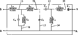
图4示出根据本发明的四端口耦合网络6’,该四端口耦合网络6’在图1所示的电路中,适用于连接放大器5与交流供电轨端A,A。在该例子中,直流供电轨端可以处于,例如,100kV至500kV数量级的电位。Figure 4 shows a four-port coupling network 6' according to the invention, which is suitable for connecting the amplifier 5 to the AC supply rail terminals A, A in the circuit shown in Figure 1 . In this example, the DC supply rail terminals may be at, for example, a potential of the order of 100 kV to 500 kV.
在使用过程中,直流变换器1在大量谐波频率处产生对交流供电轨端A、A的干扰。这些谐波可能破坏或者干扰由交流系统2供电的电气设备。有源滤波器3具有一个闭环控制回路,该闭环控制回路包括:传感装置CT、控制系统4、放大器5以及四端口网络6。如以上图1中所述,用于检测线路上的波形的传感装置CT是与该线路串联的电流互感器,以测量其上的电流,但是,可选地,还可以利用与该线路并联的电压互感器来测量该线路两端的电压。During use, the DC converter 1 generates interference to the AC supply rail terminals A, A at a large number of harmonic frequencies. These harmonics may damage or interfere with electrical equipment powered by the AC system 2 . The active filter 3 has a closed-loop control loop comprising: a sensing device CT, a control system 4 , an amplifier 5 and a four-
传感装置CT产生表示一个在交流供电轨端A,A上的谐波电流的信号,然后,反馈到控制系统4。接着,控制系统4使放大器5产生输出电流,该输出电流通过四端口网络6,使该输出电流反馈到交流供电轨端A、A。放大器5的电流输出是这样的,使得在交流系统2中观察时,变换器1产生的谐波趋向于被删除。The sensing device CT generates a signal representative of a harmonic current at the terminals A, A of the AC supply rail, which is then fed back to the control system 4 . Next, the control system 4 causes the amplifier 5 to generate an output current, which passes through the four-
需要注意的是,在图4所示的耦合电路实施例中,四端口网络包括一个梯形电路,该梯形电路具有几个下面描述的各种类型的级联部分。放大器连接到该梯形的一端,而其另一端连接到电源系统。下面说明连接到交流系统的有源滤波器的原理,与直流系统相连的有源滤波器的使用方法与下面所述的基本相同。Note that in the coupling circuit embodiment shown in Figure 4, the four-port network includes a ladder circuit with several cascaded sections of various types described below. An amplifier is connected to one end of this ladder, while the other end is connected to the power system. The principle of the active filter connected to the AC system is explained below, and the usage method of the active filter connected to the DC system is basically the same as described below.
从放大器设计的观点出发,耦合电路的重要特性是在确定的频率处或频率范围内的电压和电流的传输函数,其分别定义如下:From the point of view of amplifier design, the important characteristics of the coupling circuit are the transfer functions of voltage and current at a certain frequency or frequency range, which are respectively defined as follows:
Z12=在耦合输出短路时每1A所要求的放大器电压,Z 12 = Required amplifier voltage per 1 A with coupled output short-circuited,
I12=在耦合输出短路时每1A所要求的放大器电流。I 12 = Required amplifier current per 1A with coupled output shorted.
在输出端短路情况下定义这些传输函数的原因是,在正常操作过程中,闭环控制将在线路终端A、A上的交流系统的谐波电流,并因此将谐波电压(理想地)调节到0,从耦合电路观察,这与短路相同。The reason for defining these transfer functions in the case of a short circuit at the output is that, during normal operation, the closed-loop control takes the harmonic currents of the AC system at the line terminals A, A, and thus regulates the harmonic voltage (ideally) to 0, which is the same as a short circuit as observed from the coupling circuit.
图5示出对于图4所示的配置,放大器电压传输函数Z12和放大器电流传输函数I12。在有效带宽X上,它们二者至少具有3个零点,Z12在第12次、第24次、第36次和第48次谐波具有4个零点,而在有效带宽X内,I12在第18次、第30次和第47次谐波具有3个零点,以及在刚好位于频带X的下限之下的第10次谐波处有一个零点。FIG. 5 shows the amplifier voltage transfer function Z 12 and the amplifier current transfer function I 12 for the configuration shown in FIG. 4 . Over the effective bandwidth X, both of them have at least 3 zeros, Z 12 has 4 zeros at the 12th, 24th, 36th and 48th harmonics, and within the effective bandwidth X, I 12 at The 18th, 30th and 47th harmonics have 3 nulls, and one null at the 10th harmonic just below the lower limit of frequency band X.
仅作为一个例子,图4所示的耦合电路6’含有各种配置的串联支路10-13和并联支路14-16。根据本发明的耦合电路可以具有许多可替换的配置,包括在其传输函数中具有3、4、5、6或更多个零点的电路。As an example only, the coupling circuit 6' shown in Figure 4 contains series branches 10-13 and parallel branches 14-16 in various configurations. A coupling circuit according to the invention may have many alternative configurations, including circuits with 3, 4, 5, 6 or more zeros in their transfer function.
串联支路可以分别包括:一个单独的电感器,例如,支路12和13中的L3、L5;或一个单独的电容器,例如,支路11中的C2;或者电感器和电容器的串联组合,例如,支路10上的L1,C1。并联支路可以包括:一个单独的电感器,例如,支路14上的L2;一个单独的电容器,例如,支路15上的C3;或者电感器和电容器的并联组合,例如,支路16上的L4,C4。The series branches may respectively comprise: a single inductor, for example, L3 , L5 in
使用以下二者之一:Use one of the following:
-含有并联的电感器和电容器的串联支路,或者;- a series branch circuit containing inductors and capacitors connected in parallel, or;
-含有串联的电感器和电容器的并联支路- Parallel branch with inductor and capacitor connected in series
可以在电压和电流传输函数中产生极点,因为这二者之一可以在其谐振频率处阻挡信号从放大器沿梯形电路流动,因此,具体地说,这些设置不包括在本发明中。本发明还优选地限制于一种耦合电路,该耦合电路在其电压和电流传输函数中至少具有3个零点。Poles can be created in the voltage and current transfer functions, since either of these can block signal flow from the amplifier down the ladder at its resonant frequency, and therefore, specifically, these arrangements are not included in the present invention. The invention is also preferably limited to a coupling circuit having at least 3 zeros in its voltage and current transfer functions.
总体来说,受到上述限制,从理论上说,梯形电路部件以及它们的数量的各种配置都是可能的。然而,通常希望包括放大器和耦合电路的各部件的总成本尽可能低,尤其是在高功率设备中。由于电路配置取决于被滤波的谐波在振幅和频率上的分布,所以为了将成本降低到最低,对于不同的应用,可以优化该耦合电路中的部件的各种不同配置。In general, subject to the above constraints, various configurations of ladder circuit components and their numbers are theoretically possible. However, it is generally desirable that the overall cost of the components including amplifiers and coupling circuits be as low as possible, especially in high power devices. Since the circuit configuration depends on the distribution of the filtered harmonics in amplitude and frequency, various configurations of components in the coupling circuit can be optimized for different applications in order to minimize cost.
已经发现,在梯形电路的并联支路或串联支路中分别包括全部是一种类型的各部件(例如电容器或电感器)的配置未给出最佳配置。因此,本发明进一步限制于一种梯形耦合电路,该梯形耦合电路在一个串联支路中至少具有一个电容器,而在一个串联支路中至少具有一个电感器,同样,在一个并联支路中至少具有一个电感器,而在另一个并联支路中具有一个电容器。It has been found that a configuration including components all of one type, such as capacitors or inductors, in parallel or series branches, respectively, of the ladder circuit does not give an optimal configuration. Therefore, the invention is further limited to a ladder coupling circuit having at least one capacitor in one series branch and at least one inductor in one series branch, and likewise at least one inductor in one parallel branch. There is an inductor and a capacitor in the other parallel branch.
可以在耦合滤波器上的任何一点,例如在邻接放大器的端B-B处添加一个互感器。这样便于实现电流隔离,而且还可以提供“匹配比”,从而可以使对放大器输出电压和电流的技术要求的相对值更便于进行放大器设计。这种互感器可以具有铁芯或空气芯,在这两种情况下,为了进行设计,实际上由其内部电感形成部分梯形耦合电路。A transformer can be added at any point on the coupling filter, for example adjacent to terminal B-B of the amplifier. This facilitates galvanic isolation and also provides a "matching ratio" that makes the relative values of amplifier output voltage and current specifications easier to amplifier design. Such a transformer can have an iron core or an air core, in both cases, for design purposes, it actually forms part of a ladder-shaped coupling circuit by its internal inductance.
本发明还可以应用于连接在交流/直流变换器的直流端之间,例如在图1中的CC端,的有源滤波器,以抑制高压直流线路上的谐波干扰。其与用于交流线路的滤波器的唯一显著差别是(对于12脉冲HVDC变换器的情况)要滤波的主要谐波是第12次、24次、36次...而且在与HVDC线路的连接中,该耦合滤波器必须包括一个串联电容器(例如,在图4所示的例子中用C1示出的),以避免发生直流短路。The present invention can also be applied to an active filter connected between the DC terminals of the AC/DC converter, such as the CC terminal in Fig. 1, to suppress harmonic interference on the high-voltage DC line. The only significant difference from filters for AC lines is that (in the case of 12-pulse HVDC converters) the main harmonics to be filtered are the 12th, 24th, 36th... and in connection to the HVDC line , the coupling filter must include a series capacitor (eg, shown by C1 in the example shown in Figure 4) to avoid DC short circuits.
Claims (19)
Applications Claiming Priority (2)
| Application Number | Priority Date | Filing Date | Title |
|---|---|---|---|
| GB0213933A GB2389973B (en) | 2002-06-18 | 2002-06-18 | Improvements relating to electrical filters |
| GB0213933.5 | 2002-06-18 |
Publications (1)
| Publication Number | Publication Date |
|---|---|
| CN1663102A true CN1663102A (en) | 2005-08-31 |
Family
ID=9938759
Family Applications (1)
| Application Number | Title | Priority Date | Filing Date |
|---|---|---|---|
| CN038140675A Pending CN1663102A (en) | 2002-06-18 | 2003-06-18 | Improved electrical filters |
Country Status (5)
| Country | Link |
|---|---|
| US (1) | US20050003778A1 (en) |
| CN (1) | CN1663102A (en) |
| AU (1) | AU2003244803A1 (en) |
| GB (1) | GB2389973B (en) |
| WO (1) | WO2003107518A2 (en) |
Cited By (1)
| Publication number | Priority date | Publication date | Assignee | Title |
|---|---|---|---|---|
| CN113252993A (en) * | 2020-01-28 | 2021-08-13 | 恩智浦有限公司 | Vehicle radio interference sensor |
Families Citing this family (6)
| Publication number | Priority date | Publication date | Assignee | Title |
|---|---|---|---|---|
| US7889519B2 (en) | 2006-01-12 | 2011-02-15 | Massachusetts Institute Of Technology | Methods and apparatus for a resonant converter |
| DE102006009046A1 (en) * | 2006-02-09 | 2007-08-23 | Siemens Ag | Hybrid filter |
| US7720457B2 (en) * | 2006-10-19 | 2010-05-18 | Motorola, Inc. | Method and apparatus for minimizing noise on a power supply line of a mobile radio |
| CN101995528A (en) * | 2010-09-29 | 2011-03-30 | 上海海事大学 | Compound power filter test device and method |
| CN113820539B (en) * | 2021-08-19 | 2024-05-28 | 南京国电南自电网自动化有限公司 | Harmonic and interharmonic angle calibration method and system based on fundamental wave angle calibration |
| WO2025207792A1 (en) * | 2024-03-27 | 2025-10-02 | Lunar Resources Inc. | Deployable compact electromagnetic pulse generator munition system based on spiral generators |
Family Cites Families (11)
| Publication number | Priority date | Publication date | Assignee | Title |
|---|---|---|---|---|
| DE2749360C2 (en) * | 1977-11-04 | 1984-01-19 | Brown, Boveri & Cie Ag, 6800 Mannheim | Circuit arrangement and method for compensation of harmonic currents |
| HU202338B (en) * | 1988-01-18 | 1991-02-28 | Budapesti Mueszaki Egyetem | Active filter for filtering upper harmonics generated by a nonlinear consumer coupled on power network |
| US5397927A (en) * | 1992-08-25 | 1995-03-14 | Helionetics, Inc. | Active filter for reducing non-fundamental currents and voltages |
| US5614770A (en) * | 1994-06-06 | 1997-03-25 | Helionetics, Inc. | Structure and method for performing active injection mode filtering on an AC power system |
| US5625894A (en) * | 1995-03-21 | 1997-04-29 | Industrial Technology Research Institute | Switch filter having selectively interconnected filter stages and ports |
| US5567994A (en) * | 1995-09-29 | 1996-10-22 | Allen-Bradley Company, Inc. | Active harmonic filter with time domain analysis |
| JP3581246B2 (en) * | 1997-12-17 | 2004-10-27 | パイオニア株式会社 | Manufacturing method of bonded optical disk |
| JPH11296904A (en) * | 1998-04-03 | 1999-10-29 | Toshiba Corp | Information recording medium and method of manufacturing resin substrate used therein |
| US20020009602A1 (en) * | 2000-03-13 | 2002-01-24 | Hoya Corporation | Method and apparatus of fabricating glass molded article, method of fabricating glass substrate, and information recording medium |
| US6469485B2 (en) * | 2000-07-07 | 2002-10-22 | Honeywell International Inc. | Active filter and method for suppressing current harmonics |
| US20030007894A1 (en) * | 2001-04-27 | 2003-01-09 | Genoptix | Methods and apparatus for use of optical forces for identification, characterization and/or sorting of particles |
-
2002
- 2002-06-18 GB GB0213933A patent/GB2389973B/en not_active Expired - Fee Related
-
2003
- 2003-06-18 US US10/486,530 patent/US20050003778A1/en not_active Abandoned
- 2003-06-18 AU AU2003244803A patent/AU2003244803A1/en not_active Abandoned
- 2003-06-18 WO PCT/GB2003/002607 patent/WO2003107518A2/en not_active Ceased
- 2003-06-18 CN CN038140675A patent/CN1663102A/en active Pending
Cited By (1)
| Publication number | Priority date | Publication date | Assignee | Title |
|---|---|---|---|---|
| CN113252993A (en) * | 2020-01-28 | 2021-08-13 | 恩智浦有限公司 | Vehicle radio interference sensor |
Also Published As
| Publication number | Publication date |
|---|---|
| US20050003778A1 (en) | 2005-01-06 |
| GB2389973B (en) | 2006-02-15 |
| GB0213933D0 (en) | 2002-07-31 |
| WO2003107518A2 (en) | 2003-12-24 |
| AU2003244803A1 (en) | 2003-12-31 |
| AU2003244803A8 (en) | 2003-12-31 |
| WO2003107518A3 (en) | 2004-02-19 |
| GB2389973A (en) | 2003-12-24 |
Similar Documents
| Publication | Publication Date | Title |
|---|---|---|
| CN107565804B (en) | power conversion device | |
| US9479105B2 (en) | Input EMI filter for motor drive including an active rectifier | |
| CN103155388A (en) | Leakage current reduction device | |
| CN104081640A (en) | High frequency current reduction device | |
| CN1407702A (en) | Apparatus for reducing noise current in power converters | |
| JP2019080469A (en) | Noise reduction device | |
| CN108631630A (en) | Power inverter and power conversion system | |
| CN114208009B (en) | Power conversion device | |
| CN1871761A (en) | Apparatus for reducing noise currents in power converters | |
| US11398772B2 (en) | Circuit device for reducing common-mode interference of a power converter | |
| CN101577501A (en) | Apparatus for the transmission of electrical power | |
| CN106575927A (en) | Power conversion device | |
| US11777412B2 (en) | Switching power supply apparatus for reducing common mode noise due to line-to-ground capacitances | |
| US8587976B2 (en) | DC/DC converter with auxiliary converter for earth current compensation | |
| CN1663102A (en) | Improved electrical filters | |
| CN103004069B (en) | Power source circuit | |
| Bröcker et al. | Modular silicon carbide inverter for drive applications with high voltage slopes-challenges concerning conducted emc | |
| US12136882B2 (en) | Switching power-supply unit | |
| Kouchaki et al. | Filter design for active neutral point clamped voltage source converter using high frequency GaN-FETs | |
| Sinclair et al. | A systematic study of EMI reduction by physical converter layout and suppressive circuits | |
| Maislinger et al. | Performance of a two-stage actively damped LC filter for GaN/SiC motor inverters | |
| CN201656920U (en) | Filters and devices incorporating frequency converters and including filters | |
| CN115051581B (en) | A power supply system and charging device | |
| CN113632361B (en) | switching power supply unit | |
| CN115694154A (en) | Active rectifier in a switched mode power supply |
Legal Events
| Date | Code | Title | Description |
|---|---|---|---|
| C06 | Publication | ||
| PB01 | Publication | ||
| C10 | Entry into substantive examination | ||
| SE01 | Entry into force of request for substantive examination | ||
| C02 | Deemed withdrawal of patent application after publication (patent law 2001) | ||
| WD01 | Invention patent application deemed withdrawn after publication |