CN1628317A - Operating device for controlling functions in electronic equipment - Google Patents
Operating device for controlling functions in electronic equipment Download PDFInfo
- Publication number
- CN1628317A CN1628317A CN02822152.4A CN02822152A CN1628317A CN 1628317 A CN1628317 A CN 1628317A CN 02822152 A CN02822152 A CN 02822152A CN 1628317 A CN1628317 A CN 1628317A
- Authority
- CN
- China
- Prior art keywords
- control piece
- operating means
- switch
- sliding part
- controlling
- Prior art date
- Legal status (The legal status is an assumption and is not a legal conclusion. Google has not performed a legal analysis and makes no representation as to the accuracy of the status listed.)
- Pending
Links
Images


Classifications
-
- G—PHYSICS
- G06—COMPUTING; CALCULATING OR COUNTING
- G06F—ELECTRIC DIGITAL DATA PROCESSING
- G06F3/00—Input arrangements for transferring data to be processed into a form capable of being handled by the computer; Output arrangements for transferring data from processing unit to output unit, e.g. interface arrangements
- G06F3/01—Input arrangements or combined input and output arrangements for interaction between user and computer
- G06F3/016—Input arrangements with force or tactile feedback as computer generated output to the user
-
- G—PHYSICS
- G06—COMPUTING; CALCULATING OR COUNTING
- G06F—ELECTRIC DIGITAL DATA PROCESSING
- G06F3/00—Input arrangements for transferring data to be processed into a form capable of being handled by the computer; Output arrangements for transferring data from processing unit to output unit, e.g. interface arrangements
- G06F3/01—Input arrangements or combined input and output arrangements for interaction between user and computer
- G06F3/03—Arrangements for converting the position or the displacement of a member into a coded form
- G06F3/033—Pointing devices displaced or positioned by the user, e.g. mice, trackballs, pens or joysticks; Accessories therefor
- G06F3/0338—Pointing devices displaced or positioned by the user, e.g. mice, trackballs, pens or joysticks; Accessories therefor with detection of limited linear or angular displacement of an operating part of the device from a neutral position, e.g. isotonic or isometric joysticks
-
- G—PHYSICS
- G06—COMPUTING; CALCULATING OR COUNTING
- G06F—ELECTRIC DIGITAL DATA PROCESSING
- G06F3/00—Input arrangements for transferring data to be processed into a form capable of being handled by the computer; Output arrangements for transferring data from processing unit to output unit, e.g. interface arrangements
- G06F3/01—Input arrangements or combined input and output arrangements for interaction between user and computer
- G06F3/03—Arrangements for converting the position or the displacement of a member into a coded form
- G06F3/033—Pointing devices displaced or positioned by the user, e.g. mice, trackballs, pens or joysticks; Accessories therefor
- G06F3/0354—Pointing devices displaced or positioned by the user, e.g. mice, trackballs, pens or joysticks; Accessories therefor with detection of 2D relative movements between the device, or an operating part thereof, and a plane or surface, e.g. 2D mice, trackballs, pens or pucks
- G06F3/03548—Sliders, in which the moving part moves in a plane
-
- G—PHYSICS
- G06—COMPUTING; CALCULATING OR COUNTING
- G06F—ELECTRIC DIGITAL DATA PROCESSING
- G06F3/00—Input arrangements for transferring data to be processed into a form capable of being handled by the computer; Output arrangements for transferring data from processing unit to output unit, e.g. interface arrangements
- G06F3/01—Input arrangements or combined input and output arrangements for interaction between user and computer
- G06F3/03—Arrangements for converting the position or the displacement of a member into a coded form
- G06F3/033—Pointing devices displaced or positioned by the user, e.g. mice, trackballs, pens or joysticks; Accessories therefor
- G06F3/0362—Pointing devices displaced or positioned by the user, e.g. mice, trackballs, pens or joysticks; Accessories therefor with detection of 1D translations or rotations of an operating part of the device, e.g. scroll wheels, sliders, knobs, rollers or belts
Abstract
An operating device for controlling user functions in electronic user equipment in interaction with a display screen, and/or for controlling a means of transport, e.g., a motor vehicle, boat, ship, aircraft or the like, where the operating device has a control element having four tilting positions and central depression, with movement on rotation or sliding in at least two directions, where there is a means for force feedback, wherein the movement is actuated by an electromotor or step motor for initiating or simulating a 'step feeling', and wherein the angular extent of the movement, or the slide extent of the movement, and speed of the movement are measured, and where the 'step feeling' will be able to vary in frequency because of the extent of movement. The motor is designed to perform operations selected from the group: controlling the number of steps, controlling the distance between steps, controlling the force a user needs to apply, braking or stopping movement of the control element, causing a back or return movement, stimulating or oscillating (small reciprocating motions), detecting movement and direction of movement.
Description
Technical field
The present invention relates to claim 1,6,8-12,14,16,19 at appended claims, 22,24,26,27,31,42,44-48,50,56,58,62,66,67,68,69,76,80,89,94,102,106,110,112,113,117,119,121,124-128, disclosed a kind of operating means in 140 and 141.
The application has described new scheme and the combination about operating means or so-called multifunction switch, these devices are used for connecting use with electronic equipment, these electronic equipments preferably have a display device, these devices also are used for controlling conveying arrangement and function facility, and these conveying arrangements and function facility can have or not have the help of electronic technology or display device.The present invention be more particularly directed to usually to be called as the technology of acting force feedback, this technology is in order that can skimulated motion or for interrelating with multifunction switch or providing the feedback of impulse form with the interrelate operation carried out of a touch screen alternatively.
Background technology
Background of the present invention particularly is relatively easy to operation for the improved operation of electronic equipment and electronic equipment demand, and wishes that number of switches to be processed is minimum.Therefore, the purpose of this invention is to provide operating means, these operating means will be particularly suitable for using display device being arranged or connect in the facility of use with display device, such as various hand-held facilities or fixation means, for example, phone, mobile phone, PDA, microcomputer (PC), the multifunctional communication device is taken a picture and the foil device radio, typing and control device, programming check and analyze facility, Music center, and for the telechiric device of all types of devices and function facility.About these devices, a main target of the present invention is the simple and function that understand easily that connects with this operating means just.
It is well-known general knowledge that the small-sized device that also is of portable form develops apace, therefore, many typical product groups have begun to adopt the technology from the other products group, this be by in a device with in identical device, several application are combined realization.A typical case about this situation is multifunctional communication device or smart phone, and they are mobile phones, PDA, PC, and an assembly that also comprises camera in some cases.The device of all these types adopts a display screen, can lean on the help of this display screen to control this device, but under the situation of today, this comprises the increasing so-called keyswitch of use.
The applicant International Patent Application PCT/N096/00282 early, PCT/NO99/00373, PCT/NO00/00372, and PCT/NO01/00057 has described concrete switch solution, the some parts of PCT/NO00/00412 and PCT/NO01/00056 relates to the interaction system that is used for electronic equipment, and electronic installation is such as the mutual use of the dissimilar multifunction switchs of the electronic installation in vehicle.Preceding four patented claims above-mentioned are spoken of especially by means of so-called toggle function switch is moved on different directions, rather than remain on the fixing position, but still turn back to a starting point.
One of purpose of the present invention provides multiple switch solution, and they can substitute traditional button keyboard.Also speak of some switch in these switches in the above in the application of mentioning early.In some cases, disclosed slide switch or the feedback of physics (or entity) is in use arranged with the switch of pressure operation in these applications early, be: the stepping in slip (or ladder) is moved spring, in use, control piece that the user will be by switch or shift knob are felt these steppings.Yet the present invention can simulate this stage and move, and provide " user's pattern " of the customization of a characteristic.
Represent the further development of the schemes of describing before these to a certain extent according to the scheme that the present invention describes, and some the concrete example that provides the multifunction switch that uses the inventor for example in automobile, to use.
International Patent Application PCT/NO01/00056 speaks of the use that is installed in the multifunction switch on the bearing circle for example.Also shown and described movably combining of multifunction switch and interactional Presentation Function.The application concentrates on the multifunction switch of three following compression functions especially, and the combination of two multifunction switchs.Also show the slide switch that has four pressing positions.
Also will connect the technical scheme of speaking of multifunctional rotary switch and slide switch with the present invention.The present invention also will be shown how can produce senior still maneuverable multifunction switch, and for example in the acting force feedback system, use these multifunction switchs.This represents an importance of the application of multifunction switch, purpose is to make the user to obtain the feedback that finger can be felt by a system, multifunction switch is a part that becomes one of this system, and this multifunction switch is relevant with the motion of control piece on this class multifunction switch.
The acting force feedback that has pulse with what is called interrelates, will be with reference to United States Patent (USP) 5643087,5742278 and 6036459 for some prior art is described.Under the situation of so-called control crank (joystick), use motor that the motion of the handle of control crank is provided feedback.Usually these motor are directly connected on the handle, and the motion on the X/Y direction can be controlled or be actuated to these motor.
Summary of the invention
The present invention will concentrate on the structure of the roller switch that is used for the acting force feedback especially, and rotatable switch has five spot pressures, and the central point that also is useful on the acting force feedback departs from control piece.A kind of slide switch that five spot pressures are arranged also will be shown.
Another object of the present invention is to produce such switch: these switches can provide the feedback of physics to the user, and the control piece on switch self (operating means) must not have moving of any discernable degree.Starting point in this case is made of a plurality of solutions, and these solutions can be simulated the motion that solution has early realized.
Do not wish that employed multifunction switch and switch combination have fixing mark, for example by using silk screen printing to produce fixing mark.Wish that all information that the user needs all show on a display device.In other words, wish that multifunction switch can alternatively operate with the menu system that for example shows on lcd screen at a display screen.
In electronic installation, multifunction switch can substitute traditional keyboard, or an auxiliary member, for example for the auxiliary member that navigates.Rotate or slide and can operate this device and realize its function by interacting subsequently to pressing down this multifunction switch user with content displayed on screen.To be easy to see and the use televisor that projector and similar device connect and use the benefit that is installed in the such multifunction switch in the remote control unit.
Under the situation of vehicle, multifunction switch can be installed in bearing circle, control lever, center rest (centre console), side panel on car door and the similarity piece, is perhaps held device with one and is worked such as a remote control unit.Display unit in vehicle can connect setting with the panel board in the automobile, perhaps be arranged on panel board near, make the driver easily when driving, to see this display device, and the driver can not take sb's mind off sth by paying close attention to traffic conditions constantly.Certainly, in another remodeling, can be to windshield with information projection, as for example by known to the fighter plane.In order to allow the people who is not the vehicle driver use, can a display device be set at automobile precedence centre carriage or the front that abuts against the passenger.In this respect, an alternative position can be at the back side of dress circle, for passenger's use of back row seats, perhaps on roof, alternatively as a folding screen.
Another object of the present invention is to describe and the 26S Proteasome Structure and Function that the multifunction switch relevant with the technology that usually is called as acting force feedback (being abbreviated as FF) is shown with certain details, these multifunction switchs can skimulated motion, perhaps provides the feedback of the form of pulse for the use of the multifunction switch performed operation that interrelates.
In a word, therefore, the multifunction switch that the present invention relates to particularly to rotate or slide and the function and the structure of switch combination, they have three to five depressed position, use in that hold or fixing electronic installation and/or conveying arrangement, these devices are useful on the display part of function control or are connected on such display part.
In addition and as described, the present invention also will be referred to a plurality of switches, they represent main the further developing of the scheme that the applicant described in the past.
Below figure the general thoughts of use multifunction switch will be described, relate to particularly that to connect with they uses in vehicle may be those useful application.
Yet anyone who technology is had a common understanding will be understood that: shown and described scheme can be used in the electronic equipment of the form of ownership on being connected to the Presentation Function device.
To connect with the non-restrictive illustrative embodiment of the present invention that illustrates in the drawings now and describe the present invention in more detail.
Shown switchgear is called " operating means " or " multifunction switch ".Wish these the device with an interactional electronic user facility of display screen in control user function.Connect with the discussion of Figure 64 and will be better understood this interaction.
The characteristic clause 1,6 of the claim of the operating means of mentioning in the above, 8-12,14,16,19,22,24,26,27,31,42,44-48,50,56,58,62,66,67,68,69,76,80.89,94,102,106,110,112,113,117,119,121,124-128, in 140 and 141, and with described these independent claims in each associated appended claims in narrated characteristics of the present invention.
Description of drawings
Describe the present invention in more detail referring now to accompanying drawing, these accompanying drawings show various embodiment of the present invention.
Fig. 1 a-d shows a solution of having been known by International Patent Application PCT/NO01/00057;
Fig. 2 a-2c shows a kind of remodeling of scheme shown in Figure 1, and it has two switches of cooperating with each other;
Fig. 3 a and 3b show for a replacement scheme of scheme shown in figure 2;
Fig. 4 a-4d shows a kind of material alteration of disclosed rotation pressure switch in International Patent Application PCT/NO01/00057;
Fig. 5 a-5c shows and is used for the rotation pressure switch that the dual mode motion has pulse producer, and Fig. 5 d is the exploded view of this switch;
Fig. 6 a-6d shows an improved roller switch;
Fig. 7 a-7c shows magnet or electromagnet and the use that rotating switch connects;
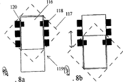
Fig. 8 a and 8b show magnet or electromagnet and the use that slide switch connects that is used for marking band breach stage by stage;
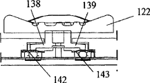
Fig. 9 a-9e shows and has a slip grasping spring and the relevant embodiment that compresses switch down;
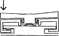
Figure 10 a-10f shows a so-called toggle formula switch;
Figure 11 a-11j shows a kind of slide switch that five following pressure points are arranged.Figure 11 k-11m shows a kind of remodeling of this scheme;
Figure 12 a-12d shows a kind of slide switch that five following pressure points are arranged.Figure 12 e shows the switch of verticity;
Figure 13 a-13f also shows a kind of slide switch that five following pressure points are arranged;
Figure 14 a-14d shows a kind of rotating switch that five following pressure points are arranged;
Figure 15 a-c shows and has a rotating switch that the fixing core of five following pressure points is arranged and the outside of four following pressure points is arranged;
Figure 16 a-16d shows a kind of rotating switch that five following pressure points are arranged, and shown in Figure 16 e-16i is being to be made into the rotating switch that four following pressure points are arranged, and Figure 16 e is the exploded view of this switch;
Figure 17 a is the skeleton view that is equipped with a kind of roller switch of three following pressure points, and Figure 17 b-17j shows this switch and its three more details of following pressure point; Figure 17 k, 17l show the more details that are connected with such construction of switch;
Figure 17 m-17o shows a kind of special remodeling at the switch shown in Figure 17 a-17j;
Figure 18 a-d shows a kind of cylinder switch that band has pressure switch mounted thereto;
Figure 19 a-19d shows the cylinder switch of a kind of " intersection " remodeling or the basic structure of roller switch;
Figure 20 a-20d shows the roller switch of at least three following pressure points, and the rotating switch of a level surrounds this roller switch;
Figure 21 a-21c shows the rotating switch of toggle function;
Figure 22 a-22d shows a kind of construction of switch based on belt, and wherein Figure 22 c and 22d show down the alternate position of pressure point, and Figure 22 e-22g shows the more details of this structure;
Figure 23 a-23c, Figure 24 a-24c, Figure 25 a-25c, Figure 26 a-26c, Figure 27 a-27c and Figure 28 a-28c show the alternate embodiment that is used for according to the working control part of operating means of the present invention;
Figure 29 a and 29b show an embodiment, wherein when rotating when pressing down in order to prevent, make the control piece of roller form not rotate;
Figure 30 shows a kind of roller switch, and it has the physical unit that is used in that rotation is stopped;
Figure 31 a-31c shows a kind of clip of the switch that is used to horizontally rotate according to principle shown in Figure 29;
Figure 32 shows a kind of slide switch, it can be pinned when pressing down;
Figure 33 shows a kind of slide switch, when the control piece motion that will stop it when pressing down.
Figure 34 a-34b shows a kind of horizontally disposed rotating switch, when when pressing down it being pinned, can not further rotate;
Figure 25 a and 35b show a kind of remodeling in the scheme shown in Figure 11, but this remodeling is equipped with the control piece of a roller shape;
Figure 36 a-36g shows a kind of remodeling of roller switch;
Figure 37 shows the roller switch that is designed for the acting force feedback;
Figure 38 shows a kind of remodeling in the scheme shown in Figure 37, but this remodeling has the rotatable control piece of a level;
Figure 39 shows the principle of the roller switch that has the acting force feedback;
Figure 40 shows second kind of roller switch, has wherein used a motor;
Figure 41 a and 41b, and 42a and 42b show the principle of having known in essence that interrelates with a step motor;
Figure 43 and Figure 44 show the remodeling in the scheme shown in Figure 41 and 42;
Figure 45 shows and uses a kind of practical embodiments of the operating means that the performance of step motor interrelates from principle;
Figure 46 a-46c shows the roller switch of three following pressure points, and it has the motor or the step motor that are contained in the inside;
Figure 47 a-47e shows a roller switch, a motor is arranged in this switch, and Figure 47 f-47u shows its remodeling;
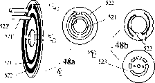
Figure 48 a-48f shows and detects the principle that substitutes of rotating;
Figure 49 a-52b shows the process of force transmission to roller switch;
The rotating switch that Figure 53 a-53c shows for five following pressure points applies acting force;
Figure 54 a-54e shows a kind of rotating switch of four following pressure points, and it has direct axial force and connects;
Figure 55 shows the rotating switch of five following pressure points as illustrated in Figure 11, and it has axial motor;
Figure 56 a-56d shows a kind of rotating switch of five following pressure points;
Figure 57 a-57c shows the another program for the rotating switch of five following pressure points;
Figure 58 a-58d shows a kind of rotating switch of four following pressure points, and it has the switch with pressure operation at a center, and this pressure switch also has the center to depart from function;
Figure 59 a-59d shows a kind of rotating belt shipper, and it has five following pressure point functions;
Figure 60 a-60g shows the remodeling of Figure 59, and Figure 60 h-60yy shows other remodeling;
Figure 61 a-61e shows the cooperation between the tumbler in variation the detection and the belt shipper from principle;
Figure 62 a-62b shows a kind of roller switch that has activated sensors;
Figure 63 shows the scheme that is used for hold function;
Figure 64 shows the connection between in environment for use switch and the different part;
Figure 65 a-65b shows the scheme that is used for five following pressure point slide switches;
Figure 66 a-66c shows the slide switch that can move by stages that is connected to five following pressure points on the motor that is used for acting force feedback (FF);
Figure 67 shows and has five following pressure point slide switches that are used for the part of acting force feedback;
Figure 68 a-68b shows five following pressure point slide switches that have the acting force feedback system;
Figure 69 a-69b shows five following pressure point rotating switches that have the acting force feedback system;
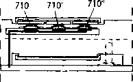
Figure 70 a-70d shows the rotating switch that can slide;
Figure 71 a-71d shows the remodeling of the roller switch that has the acting force feedback system;
Figure 72 a-72c shows the another kind remodeling of the roller switch that has the acting force feedback system;
Figure 73 a-73b shows another remodeling of the roller switch that has the acting force feedback system;
Figure 74 a-74b shows a kind of remodeling of belt shipper;
Figure 75 a-75c shows detection and the stepping scheme that is used for roller switch and rotating switch;
Embodiment
Fig. 1 a-1d shows a solution of having been known by International Patent Application PCT/NO01/00057, it is made of a kind of slide switch, there is one to press down control piece 1, this control piece is designed to by optionally starting a plurality of switches 2 to pressing down, 3,4, at least one switch in 5, wherein as shown in Fig. 1 a, control piece can overcome the elastic reaction of spring 6,7 separately or towards right or towards left movement, and wherein at separately end position pulse producer 8 is arranged, 9, simulate a kind of motion stage by stage.These pulse producers can for example work by magnetic, still, this mode should not regarded as the restriction to scope of the present invention.As the indefiniteness embodiment by Fig. 1 c can see, repeating motion to the right will demonstrate one, two, three, four and five motion stages respectively.Yet the number in stage is not limited only to five.In Fig. 1 d, illustrated for one of motion pattern alternative scheme.
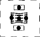
Fig. 2 a shows the operating means 10 that is used for controlling with the user function of an interactional electronic user devices of display screen (not shown), and wherein device is installed in sliding part 13; Control piece 11,12 on 14, and this device can along first axis overcome acting force of the spring act on first or second party move upward, as getting in touch illustrated in fig. 1, wherein the motion end points on sliding part 13; 14 are designed to and a pulse producer 15,16; 17,18 cooperations are used for simulating intermittent motion or motion stage by stage.As shown in the figure, control piece is provided with a plurality of pressure points down, is used for by making control piece 11; 12 inclinations or downward voltage-controlled product activate the 19-22 of switch separately that is positioned on the sliding part; 23-26.Yet,, can overcome the spring 27,28 by separately except the scheme shown in Fig. 1; 29,30 acting force of the spring that provide act on second axis direction the 3rd or the four directions to motion, this second axis direction and first axle direction form 90 degree, wherein the sliding part separately 13 on the end points of motion like this; 14 are designed to and a pulse producer 31,32; 33,34 cooperations are used for simulating intermittent motion or motion stage by stage.
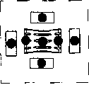
Fig. 3 a and 3b show a kind of remodeling of scheme illustrated in fig. 2.In this case, sliding part is divided into first 35 and second portion 36, they are engaged with each other with the configuration of characteristic portion (feather key) 37 and tongue 38, and first control piece 39 and second control piece 40 that wherein will be separately be arranged to can tilt with respect to their slipper, for example as shown in Fig. 1 b and the 2c.On first axial direction (parallel) with the short side of the paper of figure, two parts 35,36 can or together described first or second party move upward, perhaps only first 35 can (left) move on first direction, and second portion can (to the right) motion on second direction.At second axis direction, two parts can move independently of one another.At the end points of this motion, each slipper 35,36 is designed to and pulse producer 41 separately; 42; 43 and 44; 45; 46 cooperations.Spring 46-48 and 49-51 and sliding part separately 35; 36 is relevant, and connect the generation resistance with slip.Switch 52-54 is arranged on the control piece 35, and with switch 55,56,57 and 58 are arranged on the slipper 36, and start these switches by optionally depressing control piece 39,40.Also should be noted that, with the most close first control piece 39 therefore the switch 56 of the most close first slipper 35 be designed to also as the 4th switch for first slipper 35.
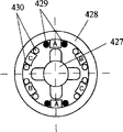
Scheme shown in Fig. 4 a-4d with can be different by the scheme that Fig. 2 b sees particularly, be: the control piece with label 59 expression in these figure can rotate about axle 60 a steppings ground on sliding part 61.A toothed edge 62 causes this step motion, toothed edge and spring assembly 63 cooperations.Depress control piece 59 at special pressure point down and will start separately switch 64-67.Reference mark 68 (only showing one of them reference mark) makes each stage of rotating to be detected by the help of ball device 69,70.About can overcome at the control piece shown in Fig. 4 c 61 spring 71,72 and 73,74 or to the left or to the right motion or on/down motion, in order that start separately pulse producer 75,76,77 and 78.
The operating means that can see by Fig. 5 a-5d will be explained in more detail.Fig. 5 a is illustrated on the vertical direction of figure paper the central segment at the operating means shown in Fig. 5 c, and Fig. 5 b represents the centre section parallel with the short side of figure paper.In this embodiment, a control piece 79 that is installed on the sliding part 80 is also arranged, this sliding part can overcome spring 81 separately along first axis, 82 act on first or second party move upward, wherein the sliding part 80 on the end points of motion is designed to and separately pulse producer 83; 84 cooperations are used for simulating intermittent motion or motion stage by stage.Control piece is provided with a plurality of pressure point (not shown) down, is used for by control piece being tilted or depressing control piece actuation switch 85-88 these switches being arranged on the sliding part 80.Control piece 79 can rotate about axle 89 a steppings ground on the sliding part, can be by means of the short circuit contact point 93 that is set to the stepping on the sliding part, 94,95, sliding contact part 91,92 on 96,97 detects the stepping position of control piece 79, perhaps can detect by means of the contact ball, this contact ball is similar with the contact element of getting in touch Fig. 4 c and label 68-70 description.Though it is not shown in Fig. 5, but sliding part 80 can overcome acting force of the spring act on second axis direction the 3rd or the four directions move upward, this second axis direction and first axle direction form the angle of 90 degree, wherein the sliding part 80 on the end points of motion like this is designed to and a pulse producer cooperation, is used for simulating intermittent motion or motion stage by stage.Therefore, the scheme shown in Fig. 5 c have a plurality of with in the common basic characteristics of scheme shown in Fig. 4 c.
It will be appreciated that by carefully studying Fig. 5 d: by means of two blocks 98 that are equipped with spring that are contained in the supporting member 100,99 realize motion stage by stage, wherein supporting member fits in the bonding part 101, polygonal shape is arranged, as label 101 ' is represented on the inside circumference of this bonding part.Like this, part 98,99 will move by stages, realize and separately relative bight joint on inner surface 101 '.
The scheme of the operating means shown in Fig. 6 a has a body 102 with spring-loaded, housing 103 supportings of this body about operating means.With body 102 be designed to by at the center to pressing down or at the downward-sloping startup in end separately switch 104,105,106 separately.As shown in Fig. 6 a and the 6c, body 102 has the sector crosssection of a circle on its top.A semicircular control piece is arranged to ride on the described top 102 ', and go up in this section can be transversal the longitudinal axis of body 102 between two end positions, slide.At an end position, control piece 107 is designed to start a switch or acting force feedback assembly 108,109.Therefore use this situation simulation in breach or the rotation on the stage.By the supporting that a frame support bracket 110 is realized body 102, this carriage passes body 102 and stretches.This can be seen by Fig. 6 b and 6d especially.Therefore it will be appreciated that: this supporting provides a center clearance, makes inclination on the end of control piece can produce the inclination about supporting member 110.
Fig. 7 shows a kind of setting of operating means, and wherein device has at least one control piece 112, and this control piece can rotate with respect to the housing 111 of device, and it is designed to by pressing down or the various switching function (not shown) of bank control.In this embodiment, magnet of She Zhiing or electromagnet 113 are installed on the described housing or are installed on the travelling carriage that can press down 115 in the housing by stages, realize that the switch support of described switching function described housing or travelling carriage, make the cooperation that in the control piece rotating process, realizes with a magnetic devices 114 on control piece by rotating, in order that demonstrate the motion stage by stage of control piece 112.
In Fig. 8 a and 8b, can see a remodeling of the scheme of describing just now.In this remodeling, a sliding part 116 that has control piece 117 is arranged, this control piece is designed to by to pressing down and/or make its tilt to realize various switching function (not shown).It will be appreciated that, Ding Wei magnet or electromagnet 118 are arranged on the housing 119 of sliding part by stages, perhaps be arranged on the housing alternatively, in order that by the motion of sliding part 116 and 120 cooperations of the magnetic devices on sliding part in housing, demonstrate or detect the motion stage by stage that can realize, also demonstrate or detect the position of sliding part with respect to housing 119 with this sliding part.
Fig. 9 a-9d shows an operating means, it has a sliding part that can move by stages 121 that has control piece 122, this control piece is designed to by to pressing down and/or make its tilt to realize various switching functions, is contained in the sliding part and the contacting metal paper tinsel part 123-127 that is positioned on the device below the sliding part realizes these functions.Holding arms 138,139,140 and 141 are connected on the action button 122 of control piece, in order that start this button by arm and extracting spring 142-145, by starting contacting metal paper tinsel part separately with the end on the sliding part 146 that sliding part 121 moves.A spring 147 that is called as the toggle spring is arranged at least one end of sliding path of sliding part 121, when sliding part 121 overcomes the effect campaign of spring, realizes so-called kick (kick) switching function by described contacting metal paper tinsel 123-137.Fig. 9 e shows a kind of modular design of the action button of control piece, but doing as a whole this design not necessarily is limited at the embodiment shown in Fig. 9.
Figure 10 shows a kind of operating means, this device be used for an interactional electronic user facility of display screen (not shown) in control user function, wherein this operating means has a sliding part 148, this part has a control piece 149, when this control piece is tilted and/or it when pressing down, the switching function that its starting switch 150,151,152 and 153 provides.Sliding part 148 can be by moving to relative extreme position at a neutral position shown in Figure 10 b, a return spring device 154 is set makes sliding part 148 get back to neutral position by an extreme position motion, as shown in Figure 10 b.The spring assembly of a motion of following sliding part for example a spider spring 155 be arranged on the sliding part, this spring be arranged to the housing 160 that is arranged on device on contact point 156-159 cooperate, this cooperation occurs at separately extreme position, as for example shown in Figure 10 f.Described contact point 156-159 can be for example on one deck contacting metal paper tinsel.
In Figure 11, can see another kind of operating means.This device has a control piece 161 that is arranged on the sliding part 162, by the pin 163 that is equipped with spring, 164 with at undulatory part on the operating means housing or the joint between the toothed part 163 ', 164 ', this sliding part can move by stages.Control piece has a plurality of for example four following pressure points, is used for by making control piece inclination or downward voltage-controlled product optionally start the switch 165 (seeing Figure 11 f) that is located on the operating means.This switch should be able to detect five and press down possibility.By means of one or more switches 175,177,179,181 (Figure 11 e); 187,189,191,193 (Figure 111) detect and are positioned at pressing down of center.On its downside, control piece 161 is preferably criss-cross, and the pin 166,167,168,169 of two starting switches is arranged on each arm of cross; 170,171,172,173.By control piece 161 is tilted or at the center to pressing down this control piece, described pin will start two switches simultaneously, such as switch 174,175; 176,177; 178,179; 180,181.Control piece 161 can be along two guide rods 182,183 motion, and this control piece is depressed in the effect that can overcome the spring 184 that is positioned at the center.Described switch represents with label 165 integrally that in Figure 11 f these switches preferably are made of a kind of contacting metal foil construction, but never will regard this structure as limitation of the present invention.
How Figure 11 g, 11h, 11i and 11j can make control piece 161 tilt if showing, so that start switch separately, two switches of one-shot.In fact control piece 161 has formed sliding part self, therefore this control piece can be along described two guide rods 182,183 motions, can on four direction, depress and tilt with respect to guide rod, and it will be appreciated that these guide rods are passed in the elliptical aperture 182 in the sliding part, 183 stretch, and these guide rods are fixed on the housing of device.
Be actually a kind of remodeling in the scheme shown in Figure 11 k-11m in the scheme shown in Figure 11 a-11j.In this case, device has a control piece 185 that is used for controlling user function, wherein this control piece has a plurality of down pressure points, is used for by control piece being tilted or downward voltage-controlled product optionally starts on the housing 194 that is arranged in operating means or is positioned at switch 186-193 on the base element 195 of housing.On its downside, control piece is criss-cross, as shown in Figure 11 m, and the button of two starting switches is arranged on each arm of cross, and for example button 196,197,198 and 199.In Figure 11 k, can not see the button pin of the starting switch on other two arms of cross.By control piece is tilted or at the center to pressing down this control piece, always can start two switches simultaneously by means of separately two pins in the described pin.
In Figure 11 k, can be clear that: control piece 185 be can stepping the part of the control knob 200 that rotates of ground.The device that a device for example has the contact field type of sliding contact part also can be set, be used for the rotation of detecting operation button.On the housing of operating means or the described switch on described base element 195 constitute by a kind of contacting metal foil construction alternatively.
Control piece (as at the control piece shown in Figure 11 a-11j) can be along about two guide rods 201, on 202 the four direction to pressing down and tilting, the elliptical aperture 201 ', 202 ' that these guide rods are passed in the control piece stretches, and these guide rods is installed in the housing of device.Action button 200 can be rotated about a pin 203, and control piece 198 self can overcome the effect of spring 204 to pressing down.
To get in touch Figure 128-12d now and getting in touch a kind of remodeling shown in Figure 12 e and describing another kind of operating means.In this embodiment, device has a control piece 205 that is installed on the sliding part 206, this sliding part is made a pin structure 207 that is equipped with spring it is moved by stages along first axial direction, undulatory inwall 208 cooperations of this structure and operating means housing.Control piece 205 is provided with a plurality of pressure points down, is used for by control piece being tilted or control piece being started the switch 209-212 and 213 that is arranged on the sliding part to pressing down.Control piece 205 is designed to depress in the centre switch 213 that it is arranged on startup in the centre of sliding part upper side.Also can be connected to control piece 205 on the spider structure 214 on the operative relationship, in order that switch 209-212 by control piece tilt to be started not in the centre.Yet, be important to note that: at a following pressure point on the side with respect to the center of control piece the switch of control piece 205 in pressing down the described switch 209-212 that startup is arranged on the sliding part downside, as being clearly shown that among Figure 12 b, switch in this case described center on side opposite on the diameter.
Be installed on the housing 215 of device and realize being connected with the circuit of switch 209-213 on the sliding part towards the bus-bar of sliding part downside.Sliding contact part 217 is arranged on sliding part, and, by means of bus-bar 218 and with sliding part on separately the contact point stage by stage 219 of sliding contact part 217 cooperation determine the position stage by stage of sliding parts.In sliding part, can be advantageously provided a wiring board 220, be used for jointly connecting each switch 209-213.
Figure 12 c and 12d show situation about taking place in a simplified manner when operating means enters running status, and by in the centre to how pressing down starting switch 213 because the spring in switch 213 sink.If an end with control piece 205 to pressing down, as shown in Figure 12 d, with starting switch 210.
Different in the scheme shown in Figure 12 e with the scheme that can see by Figure 12 a-12d.A control piece 221 is here also arranged, and this control piece is provided with a plurality of down pressure points, be used for by control piece is tilted or with control piece to pressing down optionally starting switch, such as at the switch 209-213 shown in Figure 12 a and the 12b.Not that switch is arranged on the sliding part 206, engage on the block but for example use the switches of label 222,224 and 225 expressions to be arranged on switch as one of the arm configuration in the device case 226.Control piece 221 is designed to depress in the centre switch 222 in the centre of the upper side that it is arranged on startup block 223.On the operative relationship control piece 221 is being connected on the criss-cross arm configuration 226, in order that by optionally making control piece tilt start not switch, such as 224 and 225 in the centre.Making on the downward-sloping downside that is designed to startup is arranged on block of control piece a switch of that opposite side on the diameter at described center in a side on the following pressure point with respect to the control piece center.When as arrow is represented, depressing control piece 221 subsequently, because arm configuration 226, will starting switch 225, form contact.Similarly, will starting switch 224 if press down control piece 221 in that opposite side direction on diameter of control piece.
As shown in Figure 12 e, control piece can comprise an action button 227 of can stepping ground rotating, and this button can be about 228 rotations of a supporting member.The rotation that a device is used for detecting this action button is set, for example by using contact point and sliding contact part, as label 229 and 230 represented.
Figure 13 shows a kind of operating means, wherein control piece 231 is installed on the sliding part 232, use a pin 233 that is equipped with spring, 234 can make this sliding part move by stages along first axial direction, a undulatory medial surface of these pins and operating means housing 235 or 233 ', the 234 ' cooperation of toothed medial surface.Control piece 231 has a plurality of pressure points down, is used for by control piece being tilted or control piece being started the switch 236-240 that is arranged on the sliding part to pressing down.Control piece 231 is connected on the spider structure 241, by optionally making control piece 231 tilt to start not switch 236-239 in the centre, and no matter these switches are as being provided with in such as shown in Figure 13 e or as such setting the shown in Figure 13 f.Control piece is designed to depress in the centre it startup is arranged on the switch 240 in the centre on the sliding part, be connected on the action button 231 ' of control piece one and start the center pit 241 ' that pin 242 is passed in the arm configuration and slide.By means of on the housing 235 that is arranged on device and towards the bus-bar 243 of sliding part downside realize with sliding part 232 on switch 236-240 and the downside at sliding part on the circuit of the corresponding sliding contact part integrally represented with label 244 be connected.By means of one of described bus-bar (it is represented with label 245) and with sliding part on sliding contact part 247 cooperation be arranged on the position stage by stage that contact point 246 on the described housing is determined sliding part 232 by stages.
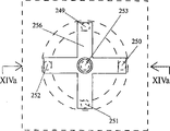
Can see another kind of operating means by Figure 14 a-14d is shown.A control piece 248 is arranged in these figure, wherein control piece can rotate about an axis by stages with its action button, and this control piece has a plurality of pressure points down, and pressure point represents that control piece optionally starts shear points or the following pressure point of the switch 249-253 on the base element 254 that is arranged in the device case 255 under these.Control piece 248 is made of described action button 248 ', and also comprises a criss-cross arm configuration 256, is used for tilting to start not switch 249-252 in the centre by the action button 248 ' that optionally makes control piece.Downward press operation button 248 ' will be enabled in the switch 253 that is positioned at the center on the base element 254 at the center.A spring assembly 257 that is fixed on the base element 254 is supporting arm configuration 256.Yet, should be noted that: arm configuration 256 can not be with action button 248 ' rotation, and therefore the contact point device 258 that is connected with upper side with the downside of action button and arm configuration 256 of sliding contact part can detect returning of action button.Be connected with circuit between described sliding contact part or the contact point and can realize in base portion 254 by means of the electric wire 259 that is arranged on the spring assembly 257.
Can see according to another kind of operating means of the present invention by Figure 15 a-15c is shown.One first control piece 260 is arranged in these figure, and its form is a ring body, and this body can rotate about second control piece that can not rotate, 261 steppings ground.First control piece 260 is provided with a plurality of down pressure points, makes by to pressing down these selected switches that presses down among first group of switch 262-265 that a little will start on the base element 266 that is arranged on device case 267 separately in pressure points down.Second control piece 261 also is provided with a plurality of down pressure points, in order that by a selected point in pressing down these points or make its tilt to start a switch among the second group of switch 268-272 that is located on the described base element 266.On its downside, second control piece 261 comprises the pin of a plurality of starting switches, and three in these pins have been shown in Figure 15 b, with label 271 ', 272 ' and 269 ' expression.By control piece 261 is tilted, the pin 268 '-271 ' of these starting switches will starting switch 268-271 in separately the switch that is not positioned at the center, and downward voltage-controlled product 261 will starting switch 272 in the centre.A spring assembly 273 that is fixed on the base element 266 is supporting second control piece 261.By means of a sliding contact part with can detect the rotation of first control piece 260 at the downside of first control piece 260 and the contact point device 274 of cooperation between a relative part 267 ' on the housing of device.
A control piece 275 is arranged in the embodiment shown in Figure 16 a-16b, this control piece can rotate by stages about an axis, wherein the action button 275 ' of control piece is provided with a plurality of down pressure points, be used for by control piece is tilted or with control piece to pressing down the switch 276-289 that starts on the base element 281 that is arranged on device case 282.On the operative relationship control piece 275 is being connected on the spider structure 283, this structure has the pin 284 of starting switch, 285,286,287, a loop configuration is perhaps arranged alternatively, and this loop configuration has the pin of a plurality of starting switches, makes by optionally making control piece tilt can start a not switch in the described switch 276-279 at center.
The pin 288 that will start 280, one starting switches of switch that are positioned at the center in the action button 275 ' of the downward voltage-controlled product in center is connected on the action button 275 ', and a center pit 283 ' that is passed in the arm configuration 283 slides.By means of a sliding contact part with can detect the rotation of action button 275 ' with the downside of action button 275 ' and device case 282 or the contact point device 289 that is connected one of base portion relative part alternatively.Action button 275 ' is engaging with 283 ' the formation spring of neck on the arm configuration or on the shoulder in described loop configuration under the help of spring assembly 290.In shown embodiment, neck 283 ' has a undulatory periphery, in order that produce the rotation stage by stage of action button under the help of spring assembly 290.
Figure 16 e-16i shows sliding contact device 291 and how forms the function cooperations with contact point device 292 on base element 293.As shown in the exploded view of Figure 16 e, toothedly take turns 294 and spring arm 295 motion that action button 275 ' is realized stage by stage by means of one.A sustained ring 297 is bearing on the base portion 293, when its is tilted with starting switch 298,299,300 and 301.As will be by Figure 16 f, g and i see like that, this remodeling of getting in touch the construction of switch that Figure 16 a-16d illustrates and describe may be compact,, provides the axial dimension than weak point possible under other condition that is.
Importantly can make control piece reach best with respect to the size in stage (control piece can move by these stages), when control piece is a dish that rotates stage by stage or action button, the diameter of its mid-game is d (is unit with the millimeter), coiling rotatable number of steps is n, according to the invention provides a constant k ε [d/n)], wherein k=1.7-2.4 millimeter/number of steps.In Figure 16 c, illustrate in greater detail this point, but will be understood that: all control pieces that this can be used for making with the action button form.
Referring now to Figure 17 a-17o and Figure 36 a-36f others of the present invention are described.
Figure 17 a shows a kind of operating means, it has the control piece 302 of a roller shape, this control piece can rotate by stages about an axle, and it is provided with a plurality of down pressure points, is used for by control piece being tilted or optionally starting and be located at a switch on the base element 303 to pressing down this control piece at the center.In shown embodiment, one toothed takes turns 304 rotations that can realize stage by stage, is provided with a spring 305 and makes this take turns rotation.
Can support control piece 302 rotatably about an axle 306 in a support 307, three switches 308,309 and 310 that are equipped with spring are supporting this support.One of switch under normal circumstances will be on a side of axle 306 such as switch 309, and as can being seen by Figure 17 d, two other switches 308 are with 310 on the relative side of axle 306.Depress the switch 309 that control piece 302 is positioned at startup at the center at the center.By at an end of control piece or the other end to pressing down, support will tilt, and with starting switch 308 or switch 310.In shown embodiment, sliding contact part and the contact point device 311 relevant with an end of the end part of support and control piece can detect the rotation of control piece 302.At this on the one hand especially referring to Figure 17 b.As shown in Figure 17 e, realize the motions stage by stage of control piece 302 by means of two pins 312,312 ' that are equipped with spring, these pins are pressing the polygonal inward flange 302 ' on control piece 302.Can be seen the further details of sliding contact part and contact point device respectively by Figure 17 e and 17j, they use label 311 ' and 311 respectively " expression.Figure 17 will be understood that by research: by downward voltage-controlled product or make its optionally starting switch 308-310 that tilts, the downside of support 307 starts relevant switch.In axle 306 elongated hole 313 ', 314 ' that are installed in the column 313,314 in the shown embodiment of Figure 17 b-17j, these columns are stretched upwards by base portion 303, perhaps stretch in the housing of device.These columns that do not draw in Figure 17 a, this is because the support in the example shown in this figure for example flexibly connects 315 and is connected on the base portion 303 by a kind of.As shown in Figure 17 h, will make control piece can move, in order that start additional switching function along axle 306.This additional switching function can for example be unclamped and contact point device 311 by sliding contact part 311 ' " contact realization.
As shown in Figure 17 k and the 17l, and also in Figure 17 a, illustrated, control piece 302 preferably in the length of control piece 302 a sizable part inwards face towards bending shaft.As shown in Figure 17 l, will be equal to, or greater than the length of control piece to the radius-of-curvature of the inside bending.
In a special embodiment, as shown in Figure 17 m-17o, in the switch at least one for example can be made a kind of biswitch structure, as label 316,316 ' is represented., show two overlapping switch member here, wherein start these switches with different starting pressures.Therefore, one to name a person for a particular job be tangible below: can starting switch 316 than switch 316 ' little starting pressure.Like this, such as connecting the function that can obtain to expand in the sort of structure that illustrates with Figure 17 a-17l.
Figure 36 shows a kind of remodeling of scheme shown in Figure 17.302, one base portion 303 of a control piece are also arranged, switch 308,309 and 310 here.The axle 306 that a vertical hole 302 ' of passing in the control piece 302 is stretched is bearing in the elongated hole of end part 316,317.Control piece 302 can be supported rotatably about a support 318, and realize motion stage by stage, be: control piece 302 has a toothed or undulatory marginal portion 302 ", this marginal portion can engage with a ball 319 that is equipped with spring.With the elongated hole in label 316 ', 317 ' the expression end part 316,317.
Scheme shown in Figure 36 also has the remodeling of detection mode, this mode relates to the turned position of finding control piece 302, realize this mode by a scheme, wherein conduction field or magnetic field 320 are set with the pattern of separating 320 ' stage by stage near axle 306.On support 318, be provided with one and read section 321, but these usually only about half of more unlike the circumference in conduction or magnetic field 320 that read that section covers.Therefore, support 318 top of cover part 320 not.Yet a lid 322 that is arranged on the top of end part 316,317 is covered with this part.By directly pressing the pin 323,324 and the hole in the base portion 303 323 ', 324 ' of stretching out to engage downwards downwards by support 318 at the center of control piece 302.Yet, sloped-end by making control piece 302 or with this end to pressing down, will make pin 323,324 rotations, the degree of rotation makes them no longer to engage with hole 323 ', 324 '.This guarantees can viciously not detect.In Figure 36 e, be provided with a brake gear 325.By control piece 302 to pressing down, obtain the friction between control piece and device 325, thereby stop rotation or rotate brake to the major general.
Interrelate with getting in touch the content that Figure 17 and Figure 36 illustrate and describe, referring now to Figure 18.
It will be appreciated that in Figure 18 a and 18b: on an end of control piece (also representing with label 302 in these figure) ring is arranged, it has n hole 326, and these holes of rotation by control piece 302 engage with the pin 327 that is equipped with spring by stages.At this on the one hand, also with reference to figure 17g.At Figure 18 a, among 18c and the 18d, second control piece and the 3rd control piece are arranged also except control piece 302, they are represented with label 328 and 329.By hinge 328 ', 329 ' these control pieces are connected on support 307 long side separately.The switch 330 and 331 that is equipped with spring be separately positioned on base element 303 and described second and the downside of the 3rd control piece between, be used for by the existing a kind of additional switching function of its downward compacting.
The size that importantly makes control piece can reach best with respect to the size in the stage that control piece can move, when control piece is a roller that can rotate by stages or rotary drum, its maximum gauge is d (is unit with the millimeter), wherein the rotatable number of steps of rotary drum is n, according to the present invention a constant k ε [d/n)], wherein k=1.5-2.0 millimeter/number of steps are arranged.Illustrate in greater detail this point in Figure 18 c, but will be understood that: this can be used for all control pieces made from roller or rotary drum form.
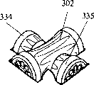
Figure 19 a-19d shows a kind of remodeling of the scheme of describing just now shown in Figure 18.It will be appreciated that here second control piece and the 3rd control piece represent with label 332 and 333 respectively, they are made the form of support, in support, can support operated roller 334,335 rotatably about axle 336,337 respectively.Axle 336 and 337 is arranged to the axle 306 of transversal first control piece 302.Represent that with label 338 and 339 hinge separately is connected.Support 332 and 333 extra switch that start are represented them as getting in touch the extra switch that Figure 18 illustrates and describes with label 330 and 331.
In Figure 19 c and 19d, show the more structural design with more details.Can see another remodeling of getting in touch the scheme that Figure 17 and 18 illustrates and describe especially by Figure 20 a-20d now.These figure also show the control piece 340 of an annular, this control piece is arranged to rotate about control piece 302 steppings of roller shape ground, and this control piece with at least three, best four switch 341-344 usefulness spring-loadeds that are equipped with spring.At the control piece of selecting that presses down the annular of naming a person for a particular job adjacent switch in pressing down meeting starting switch 341-344.By can see all the other details relevant for the description of Figure 17 with control piece 302.In the embodiment shown in Figure 20 b, control piece or roller 302,334 and 335 can be naturally with reference to the content that illustrates and describe with interrelating with Figure 18.In this case, annular control piece 340 is arranged to rotate by stages about the control piece 302 of roller shape and second and third control piece 334,335 of being hinged on its support 302.The control piece of annular with at least three, best four switches that are equipped with spring with spring-loadeds, as getting in touch Figure 20 a, 20b illustrate and as described in.At the control piece of selecting 340 that presses down the annular of naming a person for a particular job adjacent switch in pressing down meeting starting switch 341-344.
At the operating means shown in Figure 21 a-21c a control piece 345 that has action button 345 ' is arranged.Control piece 345 can rotate with respect to the housing 346 steppings ground of device, and the action button of control piece is provided with a plurality of following pressure points, in order that by descending on one selected in pressure points to a switch that presses down in one group of switch of start bit on the base element 347 of device case at these.In addition, the control piece that has its action button 345 ' can move to side direction, makes to start kick switching function or toggle formula switching function.In Figure 21 b, show this situation especially.On its bottom side, base portion 347 is provided with described a plurality of kick switch or toggle formula switch, and usefulness label 348,349 shows two in these switches.The action button 345 ' of control piece can be supported rotatably about a pivot pin 350, by 351 these pins of supporting of a center pit in the base element 347, and can be about 352 inclinations of an axle journal in the housing at its this pin of end.Fix a type star polygon work or a disk 353 in the described end of pivot pin 350.When in one direction when the side touches the button, as shown in Figure 21 b, make pivot pin 350 tilt about axle journal 352, therefore press type star polygon work or disk 353, be enabled in the switch 349 on the downside of base element, this switch is positioned on the side of pivot pin 350, and that side is opposite with the direction of motion of button 345 '.Yet, if the downward press operation button 345 ' of a point in described pressure point down will start a switch in a plurality of switches (only show two in them in Figure 21 c, promptly switch 354,355).It will be appreciated that in Figure 21 c: the switch 345 that is positioned at the upper side of base portion is activated.
The rotation of action button 345 ' can be detected with the contact point device 356 that relative with on base portion 347 one part with the downside of action button is connected by a sliding contact part.To a certain extent should with getting in touch the situation that Figure 13 and 17 illustrates and describe and connecting consideration Figure 22.Figure 22 a shows by adopting two rollers 357,358 to form control piece, and a belt 359 stretches on these two rollers.Figure 22 b shows and passes a for example cross section of roller 358 of roller, and this roller is on base portion 360.Figure 22 c and Figure 22 d demonstrate typical pressure point down, can connect with the pressing down of belt (so roller is pressed down) and use these pressure points down, in order that start the switch that interrelates with this structure.Can see this situation more detailed description by Figure 22 e.Here, it will be appreciated that: the control piece that is made of roller 357,358 and belt 359 is supported in the support 361.Activate belt 359 and will make roller 357,358 rotate, and detecting device 362 can detect, and hole or the mark 363 on one of roller passes through by stages when the motion of belt stepping ground.In order to realize motion stage by stage, a spring device 364 can for example be set, when making belt movement, this spring device with a kind of arrangement seat stage by stage the depression 365 in.Motion stage by stage and rotation are possible, as with Figure 17 and Figure 36 connect shown.
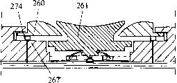
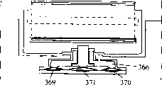
Also can be by roller 357 on operative relationship, 358, the control piece that belt 359 and support 361 constitutes is connected on the spider structure 366, in order that by optionally making unit 357-359 and 361 tilt to start not switch at the center, i.e. switch 367-370.Such as already mentioned, downward voltage-controlled product comprises that support 361 will start the switch 371 that is positioned at the center at the center, start pin 372 to one and be connected on the control piece by support 361, the center pit 366 ' that this support can pass in the arm configuration slides.
Figure 23 shows a kind of arrangement of special action button, and this button constitutes a control piece, and preferably this push-button design is become can slide on an operating means.In shown embodiment, action button has one to be the part of letting go and referring to of concave basically, and in the embodiment shown in Figure 23 and 24, these finger friction members or fitting piece can be pins 373.Alternatively, as illustrated in Figure 24, dished portion can be made a kind of undulatory structure, by the pin of a plurality of pyramidal shape or cave in and 374 constitute, as demonstrating among Figure 24.In another replacement scheme, as shown in Figure 26, can make a plurality of concentric rings 375 to dished portion.As shown in Figure 27, following situation also is possible: action button can have a surface, four finger engagement of separating or rubbing contact surface 376-379 is made on this surface, can obtain a kind of good banking motion of control piece here by its action button (integrally representing with label 380).
In another replacement scheme as shown in Figure 28, the extension 381 and the pin 382 of crescent shape arranged in dished portion.If action button is made as shown in Figure 25-28, can obtain favourable bonding part, be used for finger cooperation with the user.
Figure 29-31 shows a kind of operating means, and it is used for controlling the user function with an interactional electronic user devices of display screen (not shown) especially.This device shown in Figure 29 has a control piece 383, and this control piece can be provided with a plurality of down pressure points, is used for pressing or make its to tilt to start a switch in one group of switch downwards by the following pressure point of a selection in pressure point down.Yet, for clear, these switches that in the figure of this simplification, do not draw, but illustrated and described by front in presents and can imagine these switches immediately with reference to the content of figure.Result below hope obtained: particularly by at the center to pressing down, and by this class control piece is tilted, no matter it just like transverse axis shown in Figure 29 and 30 or as a vertical axes shown in Figure 31, in the process of starting switch, can both pin control piece, it can not be rotated.As shown in Figure 29 a and the 29b, to pressing down a kind of wedge effect that to cause between control piece 383 and the Wedge device 384.In the scheme shown in Figure 31, represent control piece with label 385, and represent Wedge device with label 386.To pressing down and can realizing wedge effect to pressing down,, thereby start a relevant switch definitely at the center of control piece therefore housing 387 pinnings of control piece 385 about operating means near its periphery.Therefore, interrelate, adopted a kind of wedge effect of clamping with the embodiment of Figure 29 and 31.Yet, in the scheme shown in Figure 30, on control piece, be provided with a plurality of parts 388 of diging up, be used for when control piece 389 is realized dig up part 388 and engaging between one on the housing 391 pinning pin 390 when pressing down.
Figure 32 and Figure 33 show two alternative schemes, and they are respectively based on scheme shown in Figure 30 with in the scheme shown in Figure 29 and 31.It will be appreciated that in Figure 32: being connected with action button 392 is provided with pin 393,394, and the part 393 ', 394 ' of diging up that they are designed in the housing with operating means forms a kind of joint that can unclamp.Yet will be understood that: except with described housing engages, if the design of control piece is not design shown here, control piece (here representing with action button 392) also can engage with a support or a supporting member.And then Figure 33 illustrates action button 396 part a 396 ' slyness or that splay, and this part is designed to form engaging of clamping with the part 397 of splaying of device case 398 when the downward pressure-controlled button.Yet, if for example operating means has another kind of design, for example be a kind of roller form, also can regard described housing 398 as for example relevantly with a support or supporting member, this support or supporting member are parts that becomes one of operating means.
In Figure 34, can see the another kind remodeling of the scheme of in Figure 32, describing just now.Here it will be appreciated that: on housing 399, be provided with a large amount of pin 400, pin in the described pin 400 and on the downside of action button 401 one dig up part or hole 402 and engage action button 410 pinnings control piece, and it can not be rotated.Structure shown in Figure 34 is also with shown in Figure 16 a-16d and the structurally associated described, so do not need further explanation.
Figure 35 shows a kind of operating means that is used for control piece 403.This control piece is arranged on the support 404, and this control piece 403 is provided with a plurality of down pressure points, is used for by control piece being tilted and optionally starting on the housing that is positioned at operating means or the switch on the base element at it to pressing down this control piece.This control piece is a roller, can be installed in it rotatably on the axle 405 of support 404, the contact point device 406 that is connected with a end with end part of support and control piece by means of a sliding contact part can detect the rotation of this roller.Preferably, still should never regard this as limitation of the present invention making a kind of contacting metal foil construction with the switch of label 407,408,409 and 410 expressions.Support can be depressed at the center, but it also can be with respect to two guide rods 411,412 tilt, these two bars pass the slotted eye 411 ' in the support, 412 ' stretches, and is installed in them in the housing of device or is installed on the part 413 that a base portion 414 by operating means protrudes upward.
By downward voltage-controlled product 403 or make this control piece tilt optionally to start described switch 407-410, thereby make the downside of support start relevant switch.Yet, a bit be important below noticing: thus perhaps by downward voltage-controlled product or control piece is tilted to pressing down support or making riding to side direction, always start two switches simultaneously.Therefore, perhaps by at the center to pressing down starting switch 407,408 together, perhaps by to laterally inclined starting switch 409 and 410.
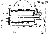
Figure 37 and 38 shows the aspect of the conceptual dependency of the present invention and " acting force feedback ".Can connect the scheme shown in Figure 37 of seeing with scheme illustrated in fig. 7 especially.The thought here is the generation magnetic of can switching on, and making has voltage between stationary part 415 and the rotatable part 416.Like this will pair roller detect and realize programming, and electricity consumption stops rotation by controlled magnetic or brake,, stop but when the end points of such menu or starting point motion, make to rotate subsequently for example when by a menu movement.Employed magnetic part is only represented with label 417 in Figure 37.In Figure 37, represent to be used for producing the power supply part of magnetic with label 418.Also can use similar techniques for control piece 419 just like vertical axes shown in Figure 38.
Figure 39-45 shows the principle that the operating means of so far describing particularly relates to a kind of remodeling of the rotatable device of control piece.Yet, also it is contemplated that the described scheme of Figure 37-45 and interrelate based on the operating means of slip.
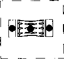
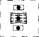
The control piece that hypothesis is represented with label 420 in the scheme shown in Figure 39 and Figure 40 and the part of the whole of so-called step motor cooperation or step motor.The step motor of this class can be connected to and carry out: the number in control stage by on the apparatus operating of selecting in the following operation, interval between the control stage, the acting force that the control user need apply, make the motion brake of control piece 420 or stop, make and to move or return to opposite direction, perhaps excite or vibrate (to-and-fro movement by a small margin), and detect motion and travel direction.As shown in Figure 39 and 40, wish that the shell of step motor forms control piece 420, keep the rotor 421 and the armature spindle 421 ' transfixion of step motor simultaneously.Yet, can imagine: can be connected to the armature spindle 421 ' of step motor on the control piece, and the shell of step motor is arranged to transfixion.In Figure 45, illustrate in greater detail this situation, wherein represent to have the control piece of an action button with label 422, with label 423 represent step motor the axle, represent the rotor of step motor with label 424, and represent the stator of motor with label 425.Can connect with step motor a rotation detector 426,426 ' is installed, detect motor case with it spool between mutual rotation, as for example shown in Figure 39.
Connecting step motor of use with a roller switch is new ideas.The thought here be in use by microprocessor is encoded can gauge tap rotation, i.e. the rotation of starting switch, the program in this microprocessor and the functional device interrelates.A purpose is that the effect field of force of simulation stepping for example is provided by means of the combination of magnet and/or electromagnet, and does not use spring and groove.By using step motor can realize the rotation of control piece (roller), the display interaction on this rotation and the display device.
This means if the user have one can turnup menu, can make the roller brake at the terminal point of menu directory or stop.In Figure 40, must install axle and rotor 421 regularly, will almost as a coating, be contained in roller on the lateral surface of motor stator 420, the stator of motor can rotate now.
Figure 41 a, 41b, 42a and 42b show a kind of principle, wherein have along the axle of roller and the field that can change in the inside of roller (alternatively that these are fixing, these are magnetic field alternatively).Label 427 expression armature spindles in Figure 41,428 expression rollers (rotor frame of motor), the lead of 429 expression energisings, and 430 expression windings.Label 431 expressions have the axle of magnetic in Figure 42,423 expression rollers (rotor frame of motor), and 433 expression windings.In fact show in this connection how to use a step motor, working method is known in others for the people who is familiar with technology.Figure 41 shows and is arranged on the roller medial surface i.e. winding on the rotary part of switch.When rotating,, realize stepping to all windings or to some selected in winding winding energisings.Further energising can brake or make it to stop, and perhaps makes the roller reverse rotation alternatively, for example interrelates with the turnup of described menu and realizes these operations.In the step motor technology, also can programme with different stepping remodeling.In one case, may wish that each circle has 18 stages for example in a plurality of stages, and in another kind of function 9 stages more suitable.
Use step motor/flux to make and adopt the winding cooperation of permanent magnet and energising to become possibility, perhaps only adopt winding, thereby can control all stages.Figure 41 shows a kind of scheme, wherein only uses winding.In this case, if not in the free opposing connection group energising of institute, will have to use fixing mechanical stepping.
The example of a winding of the magnet cooperation that Figure 42 shows and fixes.In this case, mechanical stepping can be avoided, but the possibility in the stage of removing or change stage will be limited.
Figure 43 and Figure 44 show the remodeling of Figure 41 and Figure 42.The motor rotor that label 434 expressions are installed regularly in Figure 43, roller of 435 expressions, this roller forms control piece and constitutes motor stator, in this case it is designed to and can rotates, because will keep stator to maintain static, and label 437 expressions keep motionless rotor in Figure 44, rotor frame of 438 expressions, this framework can rotate in this case, and metalwork of 439 expressions, this metalwork is magnetizable not, but by activating it to the winding energising of passing it.When a switch that can rotate, it will be suitable that the part of rotation is not carried electric current, and promptly these parts do not have winding in this case.It is inner or a rotatable disc inside that magnet or metal (this metal attracted to winding or repelled by winding) are arranged on roller (rotor frame).
About detection, it is contemplated that also and realize that by acting force and the direction of measuring magnetic field the acting force and the direction in these magnetic fields will change when using this technology rotation and direction.The possibility that also exists the principle that will describe to combine still will not discuss these in more detail here.
When adopting the flux principle advised, in order to realize to motion, the detection of its stage and direction and that extra technical equipment is installed is normally unnecessary.Will know sense of current in all moment, and the effect field of force can measure, this means the direction of motion that therefore can draw operating means.The change in the effect field of force will be represented the number in the stage that such device moves through.
The step motor technology particularly use of microminiaturized step motor technology sufficiently can be used in the operating means of a large amount of rotations and sliding type.The example of this respect can be in Fig. 7 and 8, and the remodeling of the scheme that can see among Figure 37.Therefore it is contemplated that: this scheme can be used for roller switch, rotating switch, and slide switch.
A kind of rotatable multi-functional roller switch has been shown in Figure 46 a and 46b, and it has motor or step motor and three pressing means that are installed in wherein, the function that pressurization is perhaps arranged and tilt at both direction.The operating means of switch 501 is installed on a travelling carriage or the framework 503, and the direct seat of this framework is at three spring 505-505 " on.Lifting member of label 507 expressions, this part prevents from constantly to subside downwards than the spring more than at one.The operating means 501 of switch forms the outside of motor with coil 502.Fixing the magnetic part 504 of inside subsequently.By brush 508 in known manner to coil electricity.At the other end of the rotating part of switch, detect and rotate and rotation direction, as representing with label 509.This can realize by using by a kind of technology of picking out in the technology that below will get in touch Figure 48 description.Detect operating means 501 press down or tilt to lean on be: when downward effect is applied on the switch member, the spring 505 that is installed on the following wiring board that has contact point will subside downwards.In use motor that in this switch can provide a reacting force, and the user will will feel this reacting force on his finger, as shown in Figure 46 c.This motor is common commercial product, but can be to use it with the diverse mode of normal use of this motor according to the present invention.Motor can for example be by Interlectric AG, CH-6072Sachseln, and the motor of the Maxon type that Switzerland company obtains, but also can use the motor of other type.
Figure 47 shows a kind of roller switch, and it has a motor that is installed in operating parts inside.This operating parts is installed in a framework or the travelling carriage 503, and this part can rotate with respect to framework.
Can be framework as shown in Figure 47 a, fixing, perhaps such installation the shown in Figure 47 b wherein can make switch axially press down about that root about 510 inclinations of an axle or switch.As shown in Figure 47 d, framework is by a base portion 519 and two side parts 519 and 519 ', and an intermediate connector 517 constitutes.At the framework shown in Figure 47 b a part that is fastened in it 511 is arranged, this part can move up and down, but can not rotate, can not be about axle 510 rotations.Coiler part 502 is permanently connected together with operating parts 501.Yet, the metal sleeve 520 of an iron between coil and operating parts, the path that provides the magnetic in magnetic field to return.Therefore this sleeve is with " compression " effect field of force.By being connected to the 508 pairs of coil power supplies of brush on the bonder terminal 512, see Figure 47 c.A bearing 515 is at one end supporting coil 502, and bearing between coil and magnetic part 504 514 is supporting coil at the other end.Employing can the perception reversing the Hall sensor read in this drawing rotation.Ring 516 (seeing Figure 47 a and 47d) are made of magnet, and the polarity of these magnets is changing.Two directions that 518 perception of Hall sensor are rotated and rotated.Tie point passes through in the outside of terminal 513, sees Figure 47 c.Realize in the uses stage by stage perception by the electric current of alternation being offered coil 502, from the supply of the reading control exchange current of Hall sensor 518.
Figure 47 f-47t shows the presumable compression functions down of switch, does not promptly press down, and presses down two, perhaps presses down three.In use, can with the switch junctions of handling by external pressure altogether, switch and system interaction that these external pressures are handled will connect with Figure 64 and further specify these.Also can and Fig. 1-45 connect the cooperation of this form of explanation between the roller that has acting force feedback and superincumbent switch or adjacent switch.
Figure 48 shows other replacement scheme that is used for detecting rotation, and these schemes are not the schemes that interrelates and explain with Figure 47.Can wherein realize the overlapping of resistance by adopting at the resistance that different numerical value are arranged 521,522 shown in Figure 48 a and by adopting sliding contact part 521 ', 522 ' to detect rotation.Having illustrated in Figure 48 b by going up at contact point 523 ' uses sliding contact part 523 to realize detecting.Also can use CD-ROM 524 or floppy disk 525 technology together with fluorescence detector and magnetics detecting device 524 ', 525 ' respectively, as Figure 48 c and 48d illustrate respectively.Can obtain pure optical readings by adopting to interrelate with reflection (as shown in Figure 48 e) from disk 526 ', perhaps by adopting light emitting devices 527 and optical pickup apparatus 527 ' (as shown in Figure 48 f) to obtain pure optical readings, optical pickup apparatus 527 ' can detect the hole of passing among rotatable disk 527 527 " light.Anyone who technology is had a common understanding known technology shown in Figure 48, will be not for a more detailed description therefore.
And then, will know how motor or step motor activate the switch of rotation, and wherein motor is not installed in the inside of control piece.Figure 49 shows and how operating parts or control piece 530 is connected on the gear 531 by an annular wheel edge 532.Figure 49 a-49d show gear 531 how with tooth engagement on the medial surface of operating parts 530.If in the situation of Figure 49 d, exist to the function that presses down, as shown in Figure 49 b-49c like that, gear 531 can with gear edge 532 disengagements.Such benefit is: can be motor 533 with 534 fixing to being connected of gear 531.
How Figure 50 a and 50b provides acting force by a mechanical fastener 535 if showing, this mechanical fastener for example is a kind of Bowden cable web member, a kind of fine rule web member, the web member of flexible material or flexible structure.Connect also and can connect 536 realizations by for example two universal joints of a jointed shaft.
How Figure 51 a and 51b show by a gear 538 transfer function power on the prolongation of the axle that is installed in operating parts 540.Gear 542 is installed on the motor drive shaft, this gear and gear 538 engagements.By with switch to pressing down or make switch to tilt, gear 542 will move towards motor drive shaft 537 under the help of spring 544.
Figure 52 a-52b shows the embodiment by belt 546 transfer function power.Belt will be out of shape, thus with operating parts 540 is interrelated and will not have any problem to pressing down (as represented by arrow 541).
Figure 53 a-53c show five spot pressure switches or press down and to the four directions to rotary switch, as with Fig. 1-45 of front in some figure connect the switch that illustrates.Here, shown switch is by gear 549 and the gear edge 550 on operating parts or control piece 550 " transfer function power, see Figure 53 a and 53b, alternatively just like in the sort of belt transmission shown in Figure 53 c.In both cases, the axle 548 of motor 547 is all parallel with the pivot center 550 ' of switch.Makes like this and acting force can be directly delivered on the switch operator 550, and this part has partly toothed peripheral 550 ", promptly described gear edge.
The rotating switch that Figure 54 a-54c shows a kind of four spot pressures or can tilt, wherein operating parts 552 is directly installed on the axle of motor 554.Tie point 556 on motor is spherical, and soldered tooth is arranged, and is but that on the downside of operating parts 552 one can tilt the part of the point of fixity 558 that can not rotate.Figure also shows a ring 560, when being installed in it in the device, will link together its housing with device.Disk of label 562 expression this disk is installed regularly, but it can move downward, in order that contact to spring 564 pressurizations and with contact point 566 on wiring board 568.Label 569 expressions are connected to the electrical connection on the motor 554.
Figure 55 shows a kind of rotary switch, and it has, and pressure point perhaps has the depressed position that is installed in the axial direction on the motor 573 with cubic to inclination under the center, is used for realizing the acting force feedback.Here motor drive shaft 570 passes a central spring 572 and contact point in wiring board or switch, and passes the depressed portion or the mast 576 at center.Similar with the described scheme of Figure 56 basically at this switch of others self.
To connect with Figure 56 a-56d and describe a kind of rotating switch, it compression functions is arranged under the center and to the four directions to tilting or depressed position.Switch sections 580 ' and rotation tilt and depressed portion 582 forms operating parts 580 together.This operating parts or control piece are mounted to and can rotate about frame part 584 a steppings ground.A spring 586 is fastened on part 582 and a plurality of spring, is pressing polygonal peripheral part or stepping 588 on the frame part 584.The part correlation that stretches out downwards of sloping portion 592 and part 582, this sloping portion has four arms, as a star wheel.Directly can not activate this sloping portion, but switch spring 594 will be tilted and subside when on operating parts, pressing to side direction to pressing down.A spindle unit 596 is fixedly connected on the part 582, and engages with sliding spring 598 or its remodeling 599.When operating parts rotated, spring stretched transversal wiring board 600, and a detection ring 602 is arranged on this wiring board.Label 604 is depressed portion that are implemented in the downward press operation in center, in order that spring 606 is subsided.In this structure, four horizontal inclination contact points 608 are arranged in the still parallel plane that separates, still also it is contemplated that they are arranged in the same plane.Figure 56 c shows a little change, wherein the spindle unit 596 at the center is mounted to and can moves in the axial direction about operating parts 580.The O ring that elastomeric element 610 for example can produce flexible material is installed between the part 590 and spindle unit or mast 596 of stretching out downwards.This means that when when pressing down spring and contact point in the circuit board can not be subjected to excessive power.The actual design of the contact portion of operating parts certainly changes, but for obtain at the center to the accurate sensation that presses down, in be formed centrally a little peak 580 ".For the friction force pointed is big, pattern 580 of a band ridge have also been formed at periphery in rotation process.
Figure 57 a shows a rotating switch, under its center compression functions and to the four directions to inclination or depressed position and shown in Figure 56 slightly different.Operating parts 612 constitutes by being fastened to a contact component 612 ' on the rotatable parts 614.A spring 616 is fastened on the rotating part 614, and when parts 614 rotated, this spring produced step-type motion about the part of the polygon on the star wheel or stepping 620 or about sloping portion 618.Parts 618 have four pin or four forearms 618, and their seats are on four springs 622, and a frame part 626 can not rotate them, but can tilt.Abut against contact component a 612 ' following spindle unit and pass rotatable parts 614, can rotate in the axial direction, can rotate about parts 626 and 618, and seat is on spring 624.When at the center during downward press operation spare, spring 624 will subside.A spring 630 that is used for detecting rotation stage by stage be fastened on abut against parts 614 below.Usually across crossing than a bigger a little angle of 180 degree, this spring contacts with wiring board 632 and its field 634 that contacts this spring.An O ring 636 is arranged between parts 618 and the layer insulating 638.Operating parts with the finger contact portion design in principle with described for Figure 56 identical.
To get in touch Figure 58 a-58d now and describe another remodeling of rotating switch, it compression functions is arranged under the center and to the four directions to tilting or depressed position, but this switch also additionally has the center to depart from function.A pin 650 that passes this structure centre contacts with a center control piece 652, this center control piece is moved with respect to pin 650 in the axial direction, in order that when when pressing down, spindle unit 654 being pushed away downwards, and make the center switch contact point part 668 ' on wiring board (this wiring board and the 656 ' cooperation of center contact spring) subside, and realize contact.When part 652 when being displaced sideways, will make disk 658 rotation, and the strainometer 660 that is installed on this disk detects this rotation.This will be the starting point that calculates the center side-play amount, can transmit this side-play amount, make screen point freely move on a display screen.Parts 662 and 664 form scaffolds for disk 658, and these parts are fastened on below the wiring board 666, and this wiring board comprises contact point 668, and 668 ', be used for five following pressure points and the presumable rotation of this switch solution altogether.Contact point 668 is cooperated with contact spring 656 separately.Will be noted that: pin 650 passes the hole of contact point parts in parts 668 ' at center of switch and stretches, and stretch in a hole that is passed in similarly in the contact spring 656.Now parts 651,653,655,657 will be described, 657 ', 659 and 661.Control piece of label 651 expressions, this part surrounds control piece 652.Rotatable control piece 651 rotates about a part that is fixed 653, and pin 654 passes that part that is fixed and stretches.Part 653 has toothed periphery, and under the help of spring 655 ', form spring and engage, these pins are installed on the supporting disk 657 with pin 655,655 ', and there them and axle journal 657 ', 657 " go up their holes separately and be installed together.Be provided with a rotation detector that combines and spring 659, this subassembly is cooperated with the field 663 that contacts on the wiring board 666.Be provided with a piece under pressure that can not rotate 661, be used for when part 661 being tilted or its actuation spring 656 when pressing down.Sleeve of label 665 expressions.
The switch solution that has belt to rotate is described referring now to Figure 59.Detect the principle of rotating and abideing by the principle that the front has illustrated, and never should regard restriction as this scheme.Figure 59 a is the exploded view of this structure, and this structure comprises a continuous belt 680, and this belt is round roller 681 and 682.Realize the detection of rotating at an end of roller 618 by the help of a sliding spring 684, this sliding spring contacts with contact point on the supporting member 686.The rotation that spring 688 produces stage by stage, this spring will engage with the breach (not shown) in roller 681 other ends.Roller is installed in the supporting member, and this supporting member is by framework 692, side part 694 and 696, and the core 698 of bridge shape constitutes.Framework 692 is fixedly secured on a base plate or the wiring board 702 in the central area, and framing holder is at four springs 700,700 ', 700 there " and 700 on.When under this orientation when pressing down belt 680, framework 692 will move, and one of spring will be collapsed to downwards on the wiring board 702.Because as with 692 " cross shape that illustrates has deformable ability, and framework 692 can be mobile a little.A snap switch 704 that has contact point is arranged on the bridge 698, is used for detecting pressing down at the center.Can realize such detection be because parts that can be out of shape downwards 706 directly seat on 704.Belt slides on parts 706, but belt can be out of shape, and making can be to pressing down.Parts 706 are protection switch spring 704 also, and Shi Buhui weares and teares or damage when belt is advanced on parts 706.In Figure 59 d, mark to the point that presses down with X.If the belt that goes out is as shown in the figure advanced between the exterior part 694 and 696 of framework, directly as the X of dotted line represents can realize sideways inclination to pressing down, also see label 690.
If a motor 708 is arranged on the inside of one of roller, such as the inside that is arranged on the roller 682 that is connected with motor 708, imagining a kind of acting force feedback scheme here is nature.If such scheme can cause belt to slide on roller, the scheme that adopts toothed timing belt is such as may being necessary in the scheme shown in Figure 61 a.
Figure 60 l-60g shows another remodeling of above-described belt shipper., three snap switch 710-710 ' are arranged here on bridge 712, this bridge is the part of framework 714, and it will detect on the belt at position 714-714 " pressure located.When at point 720 and 720 ' when pressing down, roller 716 with 718 by spring 722 separately and 722 ' subside and realize contacting, this is owing to roller is installed in axle head 724, in the end in 724 '.Figure 60 f show two rollers in a roller switch be installed in the remodeling in the fixed frame as described above same principle how five following pressure points 728,728 ', 728 can be arranged below belt ", 728 , 728 " ".Figure 60 g shows by using two motors 726 and 726 ' to realize that for the belt scheme acting force feeds back the possibility of (FF).Here, perhaps rod or toothed timing belt (seeing Figure 61 c and 61d) mechanically make motor synchronous, will be necessary synchronously by adopting the position probing that combines with programming to make motor perhaps.
Figure 61 a-61yy shows the different alternative exemplary of combination of the multifunction switch of roller type of belt, these examples are possible but are not exhaustively, these examples or not or have and be arranged on the bridge one below belt to five switches, perhaps wherein such be arranged on switch on the bridge by the switch that is arranged on this multifunction switch outside switch 729 for example, 729 ' and/or 729 "; 729 substitute, perhaps replenish the switch that is arranged on the bridge with these switches.
Figure 61 a and 61b show a remodeling of stage detection piece, and wherein roller 730 has tooth 732, and the ridge in roller is perhaps arranged, and are provided with a contact spring 734 or mechanical arm, and its end forms engaging of can unclamping by stages with tooth or ridge.Here tooth also can engage with the downside of belt alternatively, in order that make the rotational synchronization that detects with stage by stage, rotation stage by stage here represents with following pressure point 738 stage by stage that on roller 731 for example a ball 739 that is equipped with spring can engage with pressure point under these.For example piezoelectric elements or strainometer 733,735 can be arranged on arm or spring 734, and these parts can form the part of a measuring circuit, and therefore what this measuring circuit was used for detecting roller also is the motion stage by stage of belt.Simultaneously, provide motor message that user can hear by tooth for example to the mechanical motion of next tooth for arm 734.Imagination certainly: arm 734 and tooth 7,320 minutes are hard, to such an extent as to will there is no need a ball 739 that successively engages with recess 731 on the roller.
In Figure 61 c, also show the synchronous of roller motion.Here, for example each roller 740,741 can rotate with a common connecting link 742, perhaps as shown in Figure 61 d, roller 743,744 can by with the synchronous motion of band indented joint realization of the belt 745 that toothed trailing flank is arranged.
Figure 61 e shows roller 746 can a plurality of magnetic regions 747, and these magnetic regions stretch in the axial direction and separate round roller, forms the magnetic field of respective numbers, and when roller rotated, a magnetic field detector 748 can detect these magnetic fields.Also it is contemplated that: a permanent magnetism armature is arranged, roller design is become on this armature, rotate, wherein for example can feel resistance, thereby demonstrate in order to detect the operation stage by stage that rotation can perceive by leaving magnetic field.
Solution for the problem relevant with acting force feedback (FF) will be described under the help of Figure 62 a and 62b below.By adopting the scheme that in roller switch 751 inside a motor 750 is arranged and do not introducing fixing stepping (as in like that) on the switch, must power to motor with the electric current that fixedly stepping or obvious stepping are arranged at Figure 47 for example.When the user opens during rotating switch, can turn-on current.However, switch will be to its very loose sensation of user, and when the user begin to rotate it when making it begin to rotate switch almost can freely rotate.Take place for fear of this situation, can adopt diverse ways to detect finger and soon contact with switch.Figure 62 a shows and can use conduction technology or capacitance technology to realize such detection.When finger 752 contact with switch control piece 753, conduct electricity or capacitive transducer 753 will be sent signal by a processor (not shown), starting switch before the user begins to make its rotation.To start the stepping and the detection that realize by means of motor 750 subsequently immediately.This solution connects special importance with the saving power supply function, even this is because when the user does not have the operating multifunction switch, also will increase power consumption in the unit interval significantly to motor power supply continuously, and the electronic equipment operation be interrelated to be a problem especially like this.Figure 62 b shows a solution that substitutes that adopts optical system.Optical transmitting set 754 and receiver 755 can form light beam, can cut off these light beams when contact-making switch 756.Alternatively, it is contemplated that: receiver 755 is infrared eyes, and it can detect the existence of the heat of finger, perhaps imagines an infrared detector and can demonstrate the user near the multifunction switch on the electronic equipment.In this case, will not need optical transmitting set.
Another problem of the switch of fixing mechanical stepping will not be: when not using this switch, it will compare " pine ", that is, it can be easy to rotate in uncontrollable mode.Figure 63 shows a kind of principle, and wherein revolving part or roller 760 have 762, one piezoelectric elements in a zone to work facing to this zone, and can pin it it can not be rotated.When the polarity of voltage of this part was correct, the effect of pinning or brake will disappear.It is contemplated that two usable range: one is when not using switch it to be pinned.Another will be switch to be pinned with searching to connect in menu, interrelate and will describe this situation in more detail with Figure 64.
All schemes that provide in presents may be used to connect the system that will describe with Figure 64.In addition, all right REFERENCE TO RELATED people's International Patent Application PCT/NO00/00412 and PCT/NO01/00056, and Norwegian patent applications NO20014796.
Label 770-770 " multifunction switch that substitutes of expression, roller switch of 770 expressions wherein, tilt switch of 770 ' expression or slide switch, and 770 " rotary switch of a disc-shape of expression.These switches can be exposed to an acting force source that is used for realizing acting force feedback (FF), represent this acting force source with label 772.Detect the motion of switch with 774 one or more of representing.Processor 776 is handled these signals, and this processor is connected on the computing machine 778, is used for realizing handling with computer program 780 interactions, perhaps this processor is directly connected on the control module 772 of actuation switch.By computing machine (PC) signal is transferred on the screen 782, this screen is made response by the use of interaction partners switch and is demonstrated menu and select, function and result, and demonstrate about installing the information of 784 state for the user.Device in presents can be any device, from the mobile phone to the vehicle.With label 786 presentation functions, multi-form actuator 788 will be controlled these functions.These functions can be to start a radio signal or GPS function, and a mirror or a window are moved.
Screen picture can be according to the type change of device and function, but cursor 790 can move between subregion on the Y direction when rotation in principle, and the user can be by starting some functions or open the submenu of representing with label 794 to pressing down on switch, these functions or submenu or launch on the x of master menu direction with the cursor of following, perhaps moving cursor starts the function of transversely launching at screen.Realize that in this switch solution acting force feedback (FF) will help the user to seek best by the use of menu and function.Menu will always have a starting point and terminal point.Therefore, if can starting switch make and be ready when reaching the terminal point of menu or when having reached one group of limit for a kind of function, it is stopped or providing resistance.Wish as the applicant tells, to use multifunction switch to be implemented in the search in the screen picture and the use of function.However, can remove many compression functions down by switch, and these are pressed down function setting one-tenth independently compressing switch down on the side of tumbler.Here, known after the content of the present invention, there is the people of common understanding it will be appreciated that to technology: can use identical system, but in order to accomplish that this point user may have to more to move his finger, perhaps have to move his eyes, particularly this is not particularly advantageous when driving a car yet.
The applicant had described the multifunction switch of sliding function in the past.Figure 65 a and 65b show a kind of slide switch, the function that it has five following compression functions or presses down and tilt to four direction.Press down with tilt function with particularly with Figure 56 d connect described identical, but another kind of detection mode arranged in this case.
Travelling carriage 800 can move on a slip and area of isolation 802.A spring 804 installs on this travelling carriage, and this spring engages with stepping 806 in the switch case 808.The switch top is installed on the guiding piece, this guiding piece is connected on the sloping portion 814, wherein this sloping portion 814 is made the shape of cross.Switch control piece 810 has a lid 809, as shown in the enlarged drawing.Yet, can be part 810 with its lid 809 to pressing down, guiding piece 812 passes sloping portion 814 and slides.When in 810 ' when compressing switch downwards, guiding piece 812 will make spring 817 subside, a pin 816 that passes spring 817 will detect on the wiring board 818 and the pressure on contacting metal paper tinsel 820.Spacer layers of label 822 expressions.By means of a top part 828 guiding piece 812, sloping portion 814, the spring 815-815 that can subside, 817, will contact ball 826 with spring, the 826 ' spring that maintains 824 remains on their position.The dust cover 830 of a slip is set on this top part.Spring 824 passes the position that can slide by stages that the contacting metal paper tinsel can detect switch to ball 826 and 826 ' to pressing down.When switch is tilted, one of spring 815-815 will pass the contacting metal paper tinsel criss-cross sloping portion 814 to pressing down with extension 832 below one.In Figure 65 b, can be clear that this situation.Slide switch in this embodiment has four steppings, but should not regard this as limitation of the present invention.The downward voltage-controlled product 810 of a point in a 811-811 will make spring 815-815 separately subside, thereby by sloping portion startup contacting metal paper tinsel point separately.
As for rotating switch, certainly realize acting force feedback (FF) for the slide switch of five following pressure points.Figure 66 a and 66b show motor 840 and how can and be controlled at along an example of the travelling carriage of the stepping of y axle or position by a gear 842 and track 844 engagements in travelling carriage 846.Common understanding arranged for technology anyone can see that the motor that how to change in this system connects.An example of a remodeling has been shown in Figure 66 c, wherein motor 848 activates a belt, the arrowband, line, perhaps chain 850, this belt is round an actuating pulley or actuating wheel 852 and another pulley or take turns 852 ' stretching, extension, and wherein belt or similarity piece 850 is fastened on travelling carriage or the sliding part 854.
On the other hand, acting force feedback (FF) system will work institute's description mistake such as connecting with the figure of front and with Figure 64.
Figure 67 shows the principle of slide switch 856, the function that this switch has five following pressure points or presses down and tilt to four direction, and it has the shortest sliding path, but wherein by in order to realize that acting force feedback (FF) is to 858,860; The electromagnetism spare or the piezoelectric elements of 858 ', 860 ' expression provide electric pulse can control these electromagnetism spares or piezoelectric elements, alternatively by spring 862; 862 ' help realizes this control.It also may be suitable providing the pulse that can simulate motion stage by stage here.
Though illustrated and described the operating means of the revolving part that a button-like is arranged, but it is contemplated that: can use a similar structures that does not have rotation, promptly, operating means has the control piece of a uniform button-like, it has pressure point under the center, and four following pressure points are arranged or can tilt to four direction at peripheral part, be used for optionally starting switch operation function separately, wherein control piece is designed to when it is started the switch that is positioned at the center by a center stand column when pressing down, and wherein a type star polygon work is set or is provided with the block of arm with the relation that can slide with described column, in order that to pressing down type star polygon work is tilted by making, activates the switch separately in the peripheral part that is arranged on operating means in the control piece inclination of peripheral part or it.
For example also it is contemplated that design, but be not the stepping that to slide along a path at the operating means shown in Figure 65.Therefore, an operating means that has control piece will be arranged in the scheme of this class, this control piece is designed to by to pressing down and/or make its tilt operation that the switch separately of multiple switching function is arranged, wherein partly realize these switching functions by the contacting metal paper tinsel on device case, arm is connected on the action button of control piece, in order that when the end by type star polygon work by arm and when grasping this button of spring-actuated activates separately contacting metal paper tinsel part, control piece is designed to be able to optionally operate a function in four switching functions.In this scheme, be provided with the 5th an additional possible switching function, can overcome at the center effect of grasping spring control piece to pressing down, in order that a pin of the block by can passing linking arm and the hole motion of passing type star polygon work activates and separately the relevant switching function of contacting metal paper tinsel part.
Must with getting in touch the content association that Figure 66 and 67 illustrates and describe and getting up to see Figure 68.Its objective is the benefit of acquisition in slide switch, but have fairly simple simultaneously and compact structure more.Figure 68 shows slide switch 900, and it has an operation part 901 can moving on the both direction by arrow 903 expressions.Label 901 ' expression is for a fixed part of this operation part.Operation part has a firm surface, and this operation part is made to start five contact points with similar mode shown in Figure 65.By at the position on operation part surface 905-905 to pressing down and/or make its tilt to realize to start.The tilt component 907 that directly contacts with operation part will activate cup-shaped spring 909, and these springs just contact with contact point on wiring board 910.Wiring board is fastened on the travelling carriage 912, and this travelling carriage can move on both direction in a framework 913.By operating parts is slided, will make whole switch module motion, this assembly realize to the motion that presses down with contact, this is opposite with situation according to Figure 65, all there contacts are actionless, and only just make mechanical motion.The effect of spring 918-918 ' remains on a center with travelling carriage 912, and these springs are provided with round two spindle unit 922-922 ', and these spindle units pass framework and travelling carriage stretches.Opposite with shown in Figure 66, switch does not have fixing stepping position.By using a motor 917 to simulate stage by stage position, this motor engages with travelling carriage by gear 919.Gear engages with a track 920, in this case track is installed in switch module below.Also motor and being connected between the switch can be made as among Figure 66.However, anyone that technology is had a common understanding can see that it is possible changing.As shown in Figure 64, will be connected to motor on the computing machine or be connected on the less circuit, it comprises a processor, the screen of the user interface of computer program and display image.By means of the slip of switch, data 790 (seeing Figure 64) will be moved move a step, the user is with perceptual image " really " step.Therefore system will correspondingly make motor rotate a small step with the slip that is applied.A sensor 915 on the side in the long side of the travelling carriage in the zone 916 on close framework detects motion.It is possible for example using the principle (that is, using electric resistance sensor) of resistance here.This scheme can be determined the glide direction of operating parts simultaneously, the scope of its motion, and given movement velocity.In other words: if the user wishes that turnup only need apply very little acting force for operating parts by the catalogue of data lentamente.Produce little moving like this, sensor 915 detects this and moves, and sensor will be to information about motor starting of system, and this information is the information of motion stage by stage for the simulation under the low frequency.When being applied to bigger acting force on the operating parts, will detect bigger moving, system will send the signal of upper frequency, in order that produce stage simulation faster.The user will feel fast continuous many little stepping on switch.When data directory finishes, the pulse that applies the user on the direction of acting force will stop.When part moves in the opposite direction, the user will move in catalogue again, but be to move on other direction, and will produce the stepping sensation of pulse.Article one, deformable signal cable (not shown) is stretched by wiring board, and this cable is connected on the equipment and device that framework 913 ' and/or relevant switch will handle.
Figure 69 shows a kind of rotary switch, and it has five depressed position and acting force feedback function.This switch is a remodeling of the switch described of front, must with see this switch such as connecting at the switch shown in Figure 53-57.Operating parts is connected on the motor 926, and this motor provides the signal of certain frequency, the stepping during the analog switch rotation.Link of label 925 expressions.Therefore, switch is used for carrying out stage by stage rotation without any the groove of machinery.As the front was described, here the frequency that offers the signal of motor by change can change the number of stepping and the acting force in stepping.Similar shown in the structure of sloping portion 928 and Figure 57, but in this case it be fix and it be mounted to face down.When in order to start contact point 932-932 when four direction tilts, move with wiring board 930 and operating parts 924 around part 929.A spacer layers 931 is between wiring board and sloping portion, and this one deck is useful on the hole 931 ' of contact spring.Be pressed in contact point 933 at the center downwards and realize contact.Contact spring of label 933 ' expression.Realize passing through of electric current by means of sliding contact part 934 and 934 '.
Figure 70 a, 70b and 70c show a rotary switch of sliding function.Figure 70 c shows the section that the line LXXc-LXXc in Figure 70 d does.When pressure being applied on the operating parts 950, a central module 951 will be by means of contact point 952 and spring 951 starting switch functions.An intermediate member 954 is fixed in the operating parts, and this intermediate member comprises a spring 956.Spring will be to clamp with stepping 958 in the spindle unit 959 of the identical mode shown in Figure 56 on a groove and the travelling carriage 960.When rotation, just have the motion stage by stage of operating parts.Travelling carriage 960 can be with respect to 962 motions of a framework.Two spring parts 963 and 964 adjacent below travelling carriage are 963 ' and 964 '.Two wire spring 965-965 ' are with these spring part biasings.This means: operating parts will remain on the center when not activateding.A sliding contact spring 968 is fastened on the travelling carriage, and this spring contacts with contact area on the wiring board.When operating parts slides, by means of spring by 971 ' to 972 or 972 ' mobilely detect this slip.The direction that label 973 expressions are slided.As in the scheme of describing in front, a sliding contact spring 969 that contacts with contact area 971 detects the rotation of operating parts.The sliding contact spring is fastened on the rotatable parts 970, and then these rotatable parts is fastened on the core or central module 951 of operating parts.Ring of label 974 expressions, it is insulating at the contact element at center and the remainder of contact area.As the people that are familiar with technology will recognize that, scheme also can realize the acting force feedback system hereto.Obviously adopted the scheme that connects description with Figure 68 here.Adopt described in the above description and at the rotary switch of crossing shown in the relevant figure, four of also can be used at an easy rate add press down and/or obliquity this scheme.
Figure 71 a-71b shows a remodeling in the scheme shown in Figure 46-47.These illustrate a roller switch, and wherein operating parts can be with magnetic part 982 motions of motor.Winding 984 is fixed in this scheme.Label 986 and 987 expressions are used for detecting the system of rotation, as shown in Figure 47.Figure 71 a and 71b are respectively the sectional view and the planimetric maps of this scheme, and Figure 71 c is the exploded view of the skeleton view of Figure 71 d.
Figure 72 a-72c shows a remodeling, wherein is provided with the web member 990 and 991 that is used for power supply and signal output in each side of switch.We also see in these figure: a ball web member 994 is fixed movable switch block.This has guaranteed when the motion when pressing down, because such motion is actually the motion on three directions.We see how spring and contact point 996-996 ' are scattered in a triangle.Figure 72 a is the sectional view that the line LXXIIa-LXXIIa in Figure 72 b does.
If wishing has a big switch, can with several fingers operate it or by the bigger motion action of finger it, Figure 73 a shows the design of a roller switch of acting force feedback system.The technical pattern of others described as the front and illustrated.There is the recess 1001 of a feature on the surface of operating parts 1000 at the center in this case, and the part 1002-1002 ' of a band tapering is arranged on each side.This shape prevents that the user from carrying out incorrect pressing down.How Figure 73 b can constitute this roller switch if schematically showing purely.
Figure 47 shows a remodeling that connects the belt shipper that illustrates and described with Figure 59.Two schemes all have rotation and in the function of five depressed position starting switches.Their main difference will be described below.When belt 1020 rotates (this belt is about cylinder 1021 and 1022 rotations), the ball 1024 that is equipped with spring will be advanced in the stepping in the end 1,027 1026.Also, a kind of stepping that combines and detection scheme have been this figure also illustrates referring to Figure 74.The center recess of this belt shipper remodeling is firmly fastened on a bridge 1032, and this bridge is with framework 1030 motions, but makes its keep being fixed on the wiring board 1031 by means of its end.
Figure 75 shows the principle that the step motion that will detect and rotate that is used for the rotating switch scheme combines.This embodiment can save the parts in rotating switch.The example of using a roller switch spare 1040 shown here.Detection and stepping zone 1041 are made of lifting member 1042, and these lifting member are made or coated with conductive material by a kind of conductive material.1043 of Metal Ball that is equipped with spring are on zone 1041.Rotation by operating parts 1040 will obtain motion stage by stage.In addition, it will be possible detecting rotation with the method for electronics, be: for example other lifting member 1042 is connected on the common electric-conductor (not shown) each, and other middle lifting member 1042 ' is connected on another common electric-conductor (not shown).When roller rotates, ball will form contact stage by stage between the lifting member relevant with separately common electric-conductor, thus each time between lifting member by the time between two electric-conductors, form contact.If be connected on the 3rd terminal by the spring handle ball, the direction that detects rotation also will be possible, this is because ball forms contact between two electric-conductors in one case, and any one electric-conductor contacts with lifting member 1040 or 1042 formation in another case.
Claims (142)
1. operating means that is used for controlling with the user function of the interactional electronic user devices of display screen, and/or be used for controlling for example motor vehicles of conveying arrangement, canoe, ship, the operating means of aircraft or similar device, wherein this device has the control piece that is installed on the sliding part, the effect that this sliding part can overcome acting force of the spring along first axle first or second party move upward, wherein the sliding part on the end points of motion is designed to and is used for simulate the pulse producer cooperation of motion intermittently or stepping, and wherein control piece is provided with a plurality of spot pressures, is used for by control piece being tilted or control piece being activated the switch that is positioned on the sliding part to pressing down;
It is characterized in that:
The effect that sliding part can also overcome acting force of the spring along second axis direction the 3rd or the four directions move upward, this second axis direction and first axle direction form the angle of 90 degree, wherein the sliding part on the end points of motion like this are designed to and are used for simulate the pulse producer cooperation of motion intermittently or stepping.(Fig. 2)
2. according to the described operating means of claim 1, it is characterized in that,
Sliding part is divided into first and second portion, and these parts are engaged with each other with feather key and joint tongue configuration, have first and second control pieces separately on the slipper that can be bearing in them obliquely;
On first axial direction these two parts or can be together first or second party move upward, perhaps only first can move and second portion can move upward in second party along first direction;
These two parts can move independently of one another on second axial direction; And
Sliding part on the end points of motion is designed to and a pulse producer cooperation.(Fig. 3)
3. according to the described operating means of claim 2, it is characterized in that,
First is equipped with three switches, by first control piece to pressing down or make these switches of the downward-sloping actuating of first control piece; And
Second portion is equipped with four switches, by second control piece to pressing down or make these switches of the downward-sloping actuating of second control piece.(Fig. 3)
4. according to the described operating means of claim 3, it is characterized in that,
That switch designs of the most close first control piece in described four switches is become also as the 4th switch for first.(Fig. 3)
5. according to the described operating means of claim 1, it is characterized in that,
Control piece can rotate about an axle stepping ground on sliding part.(Fig. 4)
6. operating means that is used for controlling with the user function of an interactional electronic user devices of display screen, and/or be used for controlling for example motor vehicles of conveying arrangement, canoe, ship, the operating means of aircraft or similar device, wherein this device has and is installed in a control piece on the sliding part, the effect that this sliding part can overcome acting force of the spring along first axle first or second party move upward, wherein the sliding part on an end points of motion is designed to and is used for simulate a pulse producer cooperation of motion intermittently or stepping, and wherein control piece is provided with a plurality of pressure points down, is used for by control piece being tilted or control piece being activated the switch that is positioned on the sliding part to pressing down;
It is characterized in that:
Control piece can rotate about an axle stepping ground on sliding part, can or detect the position stage by stage of control piece by means of a pair of sliding contact part, the sliding contact part is designed to short circuit contact point stage by stage on sliding part, perhaps can detect the position stage by stage of control piece by means of the contact ball, these contact balls actuation switch alternately is provided with these switches by stages with respect to the rotation stage by stage of control piece.(Fig. 5 a/5b)
7. according to the described operating means of claim 6, it is characterized in that,
The effect that sliding part can also overcome acting force of the spring along second axis direction the 3rd or the four directions move upward, this second axis direction and first axle direction form the angle of 90 degree, wherein the sliding part on an end points of motion like this are designed to and are used for simulate a pulse producer cooperation of motion intermittently or stepping.
8. operating means that is used for controlling with the user function of an interactional electronic user devices of display screen, and/or be used for controlling for example motor vehicles of conveying arrangement, canoe, ship, the operating means of aircraft or similar device, wherein this device has and is installed in a control piece on the sliding part, the effect that this sliding part can overcome acting force of the spring along first axle first or second party move upward, wherein the sliding part on an end points of motion is designed to and is used for simulate a pulse producer cooperation of motion intermittently or stepping, and wherein control piece is provided with a plurality of pressure points down, is used for by control piece being tilted or control piece being activated the switch that is positioned on the sliding part to pressing down;
It is characterized in that:
Control piece can rotate about an axle stepping ground on sliding part; And
The effect that sliding part can also overcome acting force of the spring along second axis direction the 3rd or the four directions move upward, this second axis direction and first axle direction form the angle of 90 degree, wherein the sliding part on an end points of motion like this are designed to and are used for simulate a pulse producer cooperation of motion intermittently or stepping.(Fig. 5)
9. operating means that is used for controlling with the user function of an interactional electronic user devices of display screen, and/or be used for controlling for example motor vehicles of conveying arrangement, canoe, ship, the operating means of aircraft or similar device, wherein device has one by the body of spring-loaded, is supporting this body about the housing of operating means, and wherein body is designed to by in separately end at the center to pressing down or make its downward-sloping actuating to be arranged on switch separately in the housing
It is characterized in that:
This body has the section cross section of a circle on top; And
A semicircular control piece is designed to ride on the described top, and this control piece can slide between two end positions at the longitudinal axis of transversal body on the described part, be designed to activate switch or the acting force feedback assembly that is arranged in the housing at the control piece of end separately, in order that simulation rotation stage by stage.(Fig. 6)
10. operating means that is used for controlling with the user function of an interactional electronic user devices of display screen, and/or be used for controlling for example motor vehicles of conveying arrangement, canoe, ship, the operating means of aircraft or similar device, wherein device has at least one control piece, and this control piece can rotate with respect to the housing of device, and this control piece is designed to by to pressing down and/or make the multiple switching function of its bank control
It is characterized in that:
The magnet or the electromagnet that are provided with by stages are arranged on the described housing, be arranged on the part of housing, one that perhaps is arranged in the housing can be on the travelling carriage that presses down, switch support this travelling carriage, those magnets are handled described switching function, in order that by making control piece rotation and magnetic devices cooperation on control piece, provide the demonstration of the motion stage by stage of control piece and/or detect the motion stage by stage of (determining) control piece, realize the acting force feedback and/or rotate.(Fig. 7)
11. operating means that is used for controlling with the user function of an interactional electronic user devices of display screen, and/or be used for controlling for example motor vehicles of conveying arrangement, canoe, ship, the operating means of aircraft or similar device, wherein device has a sliding part that can move by stages, and it has a control piece, this control piece is designed to by to pressing down and/or make the multiple switching function of its bank control
It is characterized in that:
The magnet or the electromagnet that are provided with by stages are arranged on the sliding part, perhaps be arranged on the sliding part housing, in order that by make sliding part motion respectively with magnetic devices cooperation on housing or sliding part, in order that demonstrate or detect the motion stage by stage of sliding part and sliding part position with respect to housing.(Fig. 8)
12. operating means that is used for controlling with the user function of an interactional electronic user devices of display screen, and/or be used for controlling for example motor vehicles of conveying arrangement, canoe, ship, the operating means of aircraft or similar device, wherein this device has a sliding part that can move by stages, and it has a control piece, this control piece is designed to by to pressing down and/or make the multiple switching function of its bank control
It is characterized in that:
Partly realize switching function by the contacting metal paper tinsel that on the housing of device, is arranged on below the sliding part, holding arms is connected on the action button of control piece, in order that by the actuating of the end on type star polygon work contacting metal paper tinsel part separately, this type star polygon work can be moved with sliding part when by arm and extracting spring it being started.(Fig. 9)
13., it is characterized in that according to the described operating means of claim 12:
A so-called elbow spring is arranged at least one end of the sliding path of sliding part, in order that realize so-called " kick switch " function by described contacting metal paper tinsel when overcoming the acting force sliding moving part of spring.
14. operating means that is used for controlling with the user function of an interactional electronic user devices of display screen, and/or be used for controlling for example motor vehicles of conveying arrangement, canoe, ship, the operating means of aircraft or similar device, wherein this device has a sliding part, it has a control piece, this control piece tilts and/or the startup of switching function now of compacting downwards by making it, and wherein sliding part can move to relative extreme position by a neutral position
It is characterized in that:
A spring assembly for example spider spring is arranged on the sliding part, is used for and the contact point cooperation, and these contact points are arranged on the housing of device the extreme position separately, and towards a slidingsurface; And
Be provided with a return spring device, be used for making sliding part to get back to neutral position by an extreme position motion.(Figure 10)
15., it is characterized in that according to the described operating means of claim 14:
Contact point is on a contacting metal paper tinsel.
16. operating means that is used for controlling with the user function of an interactional electronic user devices of display screen, and/or be used for controlling for example motor vehicles of conveying arrangement, canoe, ship, the operating means of aircraft or similar device, wherein this device has and is installed in a control piece on the sliding part, this sliding part can move along the first axle direction, and wherein control piece is provided with a plurality of down pressure points, is used for by control piece being tilted or control piece being positioned at switch on the housing of operating means to pressing down optionally actuating;
It is characterized in that:
Control piece is criss-cross on its downside, and control piece has the pin of two actuation switchs on each arm of cross, make by making control piece tilt always can start two switches simultaneously by means of described pin, and by at the center downward voltage-controlled product will start at least one, maximum four switches.(Figure 11)
17., it is characterized in that according to the described operating means of claim 16:
Switch is made of contact-making switch, for example is made of the contacting metal foil construction.
18. according to claim 16 or 17 described operating means,
It is characterized in that:
Sliding part can move along two guide rods, can be with respect to these guide rods to pressing down and can tilting at four direction with respect to these guide rods, and the elliptical aperture that these guide rods pass in the sliding part stretches, and they are arranged in the housing of device.
19. operating means that is used for controlling with the user function of an interactional electronic user devices of display screen, and/or be used for controlling for example motor vehicles of conveying arrangement, canoe, ship, the operating means of aircraft or similar device, wherein this device has and is installed in a control piece on the sliding part, this sliding part can move along the first axle direction, and wherein control piece is provided with a plurality of down pressure points, is used for by control piece being tilted or control piece being positioned at switch on the housing of operating means to pressing down optionally actuating;
It is characterized in that:
A switch that is arranged on the center on the upper side that is designed to be enabled in sliding part at the downward voltage-controlled product in center;
On the operative relationship control piece is being connected on the criss-cross arm configuration, in order that by optionally making control piece tilt-activated not at the switch at center; And
Make at a following pressure point place on the side control piece with respect to the center of control piece a switch on the opposite side on the diagonal line at described center on the downward-sloping downside that is designed to be enabled in sliding part.(Figure 12)
20., it is characterized in that according to the described operating means of claim 19:
Realize and being electrically connected of switch by being arranged on the device case towards the bus-bar of the downside of sliding part and the sliding contact part on sliding part, by means of bus-bar and the contact point that is provided with stage by stage determine the position stage by stage of sliding part, the sliding contact part cooperation on these contact points and the sliding part.
21., it is characterized in that according to claim 19 or 20 described operating means:
Wiring board is contained in the sliding part.
22. operating means that is used for controlling with the user function of an interactional electronic user devices of display screen, and/or be used for controlling for example motor vehicles of conveying arrangement, canoe, ship, the operating means of aircraft or similar device, wherein this device has and is installed in a control piece on the sliding part, this sliding part can move along the first axle direction, and wherein control piece is provided with a plurality of pressure points down, is used for by control piece being tilted or control piece optionally being activated the switch that is positioned on the sliding part to pressing down;
It is characterized in that:
On the operative relationship control piece is being connected on the criss-cross arm configuration, in order that by optionally making control piece tilt-activated not at the switch at center; And
Center at control piece is designed to start a switch that is arranged on the sliding part center to pressing down, is connected on the control knob of operating means one and activates the center pit that pin is passed in the arm configuration and slide.(Figure 13)
23., it is characterized in that according to the described operating means of claim 22:
Realize and being electrically connected of switch on sliding part by being arranged on the device case towards the bus-bar of the downside of sliding part with at the sliding contact part on the sliding part, by means of bus-bar and the contact point that is provided with stage by stage determine the position stage by stage of sliding part, the sliding contact part cooperation on these contact points and the sliding part.
24. operating means that is used for controlling with the user function of an interactional electronic user devices of display screen, and/or be used for controlling for example motor vehicles of conveying arrangement, canoe, ship, the operating means of aircraft or similar device, wherein this device has a control piece, it has an action button, this action button can be rotated about an axis stepping ground, and be provided with a plurality of down pressure points, be used for by control piece being tilted or control piece being positioned at switch on the base element of housing of operating means to pressing down optionally actuating;
It is characterized in that:
Control piece comprises a criss-cross arm configuration, in order that by optionally making control piece tilt-activated not at the switch at center;
Downward pressure-controlled is designed to start a switch that is positioned at the base element center at the center;
A spring assembly that is fixed on the base element is supporting arm configuration; And
The rotation of action button can detect by means of the contact point device that a sliding contact part is connected with upper side with the downside of action button and arm configuration.(Figure 14)
25., it is characterized in that according to the described operating means of claim 24:
Be arranged on electric wire in the spring assembly and realize being electrically connected between base portion and the sliding contact part.
26. operating means that is used for controlling with the user function of an interactional electronic user devices of display screen, and/or be used for controlling for example motor vehicles of conveying arrangement, canoe, ship, the operating means of aircraft or similar device, wherein this device has first control piece that is made into the ring body form, it can rotate about the second control piece stepping ground that can not rotate, wherein first control piece is provided with a plurality of pressure points down, in order that by at its one selected point to a switch that presses down first group of switch on the base element that activates the housing be arranged in operating means, and wherein second control piece is provided with a plurality of down pressure points, in order that by a switch at the second group switch of its one selected point on a base element that presses down or make its tilt-activated housing that is arranged in operating means;
It is characterized in that:
Second control piece comprises a plurality of actuation of the switch pins on its downside, in order that by making a switch at the center that is not arranged in the optionally tilt-activated switch of control piece, and by at the center downward voltage-controlled product start bit in a switch at base element center;
A spring assembly that is fixed on the base element is supporting second control piece; And
The rotation of first control piece can by means of a sliding contact part with detect with the contact point device of a relative partial cooperation of the downside of first control piece and device case.(Figure 15)
27. operating means that is used for controlling with the user function of an interactional electronic user devices of display screen, and/or be used for controlling for example motor vehicles of conveying arrangement, canoe, ship, the operating means of aircraft or similar device, wherein this device has a control piece, it can rotate about an axis stepping ground, and wherein the action button of operating means is provided with a plurality of down pressure points, is used for by control piece being tilted or control piece being positioned at switch on the base portion of housing of operating means to pressing down optionally actuating;
It is characterized in that:
Have on the criss-cross arm configuration of actuation of the switch pin in the end of arm or be connected on the annular arm structure of a plurality of actuation of the switch pins on the operative relationship control piece being connected to, in order that by optionally making the tilt-activated not switch in the switch at center of control piece.(Figure 16)
28., it is characterized in that according to the described operating means of claim 24:
Center at control piece is designed to start a switch that is arranged on the base portion center to pressing down, is connected on the control knob of operating means one and activates the center pit that pin is passed in the arm configuration and slide.(Figure 16 a)
29., it is characterized in that according to the described operating means of claim 27:
Can detect the rotation of action button by means of a sliding contact part and the contact point device that is connected with the downside and relative part device case or on base portion of action button.
30. according to one or more the described operating means among the claim 27-29,
It is characterized in that:
Action button under the help of a spring assembly with of arm configuration on neck or form spring with a shoulder of loop configuration and engage; And,
Around this neck is corrugated, is used for realizing under the help of spring assembly the rotation stage by stage of action button.
31. operating means that is used for controlling with the user function of an interactional electronic user devices of display screen, and/or be used for controlling for example motor vehicles of conveying arrangement, canoe, ship, the operating means of aircraft or similar device, wherein this device has the control piece of a roller shape, it can rotate about an axle stepping ground, and be provided with a plurality of down pressure points, be used for by control piece being tilted or control piece being positioned at switch on the base element of housing of operating means at the center to pressing down optionally actuating;
It is characterized in that:
Can support control piece rotationally about an axle in the support, three switch support that are equipped with spring this support, and one of switch is in a side of axle, and two switches are in that relative side of axle in addition;
Downward voltage-controlled product is designed to start a switch that is positioned at the base element center at the center; And
Can by means of a sliding contact part with detect the rotation of operating parts with end part of support and the contact point device that is connected with an end of the upper side of the downside of the action button of control piece and arm configuration.(Figure 17; Figure 36)
32., it is characterized in that according to the described operating means of claim 31:
Can or make the control piece optionally starting switch that tilts by downward voltage-controlled product, thereby the downside of support can activate relevant switch.
33. according to claim 28 or 29 described operating means,
It is characterized in that:
Axle is bearing in the elongated hole in column or the side part, and these columns or side part stretch upwards by base portion or in device case.
34. according to one or more the described operating means among the claim 31-33,
It is characterized in that:
Control piece can move along axle, is used for starting additional switching function.
35. according to one or more the described operating means among the claim 31-34,
It is characterized in that:
Control piece is to the inside bending, towards axle, along sizable part of control piece length.
36., it is characterized in that according to the described operating means of claim 35:
Be equal to, or greater than the length of control piece to the radius-of-curvature of the inside bending.
37. according to claim 31 or 32 described operating means,
It is characterized in that:
At least one switch is made up of a biswitch structure, and this structure is made of two overlapping switch member, and different starting pressures starts each switch member.(Figure 17 m-o)
38. according to one or more the described operating means among the claim 31-36,
It is characterized in that:
The second and the 3rd control piece is connected on the long side separately of support with hinge respectively;
With a switch that is equipped with spring be arranged on base element and described second and the downside of the 3rd control piece between, in order that the switching function that now replenishes by downward compacting.(Figure 18)
39. according to the described operating means of claim 38,
It is characterized in that:
The described second and the 3rd control piece is made the form of a support, in this support, can support an operated roller by stages rotatably about an axle in the support; And
The rotation of operated roller can by means of a sliding contact part with detect with an end part of support and the contact point device that is connected with an end of operated roller.(Figure 19)
40. according to one or more the described operating means among the claim 31-36,
It is characterized in that:
The control piece of an annular is set, make it to rotate by stages about the control piece of roller shape, and with at least three, best four switches that are equipped with spring with spring-loaded it, will start at the selected downward pressure ring shape of following pressure point control piece a nigh switch is set.(Figure 20 a-c)
41., it is characterized in that according to the described operating means of claim 39:
The control piece of an annular is set, make it to rotate by stages about the control piece of roller shape and the described second and the 3rd control piece that is hinged on its support, wherein should the annular control piece with spring-loaded with at least three, best four switches that are equipped with spring, will start at the selected downward pressure ring shape of following pressure point control piece a nigh switch is set.(Figure 20 d)
42. operating means that is used for controlling with the user function of an interactional electronic user devices of display screen, and/or be used for controlling for example motor vehicles of conveying arrangement, canoe, ship, the operating means of aircraft or similar device, wherein this device has a control piece, it can rotate with respect to the housing stepping ground of device, wherein control piece is provided with a plurality of pressure points down, in order that by at its one selected point to a switch that presses down one group of switch on the base element that activates the housing be arranged in operating means, and wherein control piece can also move to side direction, starts kick switching function or elbow switching function
It is characterized in that:
Base portion is provided with a plurality of described kick switches or elbow switch on its downside;
Can support the action button of control piece rotatably about a pivot, support this pivot by a center pit in the base element with certain clearance, and this pivot can be about an axle journal on described housing, and a type star polygon work or a disk that is fixedly mounted on the described end of pivot tilt;
When in one direction to the side button push, can make trunnion axis tilt, therefore make type star polygon work or disk be enabled in a switch on the downside of base element, type star polygon work or disk are positioned at a side of pivot, and this side is opposite with the direction of motion of button.(Figure 21)
43., it is characterized in that according to the described operating means of claim 42:
Can by means of a sliding contact part with detect the rotation of action button with the downside of action button and the contact point device that is connected with a relative part on the base portion.
44. operating means that is used for controlling with the user function of an interactional electronic user devices of display screen, and/or be used for controlling for example motor vehicles of conveying arrangement, canoe, ship, the operating means of aircraft or similar device, wherein this device has a control piece, and it is provided with a plurality of pressure points down, is used for by control piece being tilted or control piece optionally being activated the switch that is positioned on the sliding part to pressing down;
It is characterized in that:
On the operative relationship control piece is being connected on the criss-cross arm configuration, in order that by making control piece tilt-activated not at the switch at center;
Downward pressure-controlled is designed to start a switch that is positioned at the center at the center, is connected on the action button of control piece one and activates the center pit that pin is passed in the arm configuration and slide;
Control piece is made the form of a support, and at least two rollers of separating can be installed in this support rotatably, and a continuous belt rotates on these two rollers;
Device is relevant with a roller in the roller, is used for detecting its rotation stage by stage, thereby makes operating means can realize an additional control piece function.(Figure 22)
45. operating means that is used for controlling with the user function of an interactional electronic user devices of display screen, and/or be used for controlling for example motor vehicles of conveying arrangement, canoe, ship, the operating means of aircraft or similar device, wherein this device has a control piece that is made into the roller form, and it can rotate about the housing stepping ground of an axle with respect to device
It is characterized in that:
Control piece is to the inside bending, towards axle, along sizable part of control piece length; And
Be equal to, or greater than the length of control piece to the radius-of-curvature of the inside bending.(Figure 171)
46. operating means that is used for controlling with the user function of an interactional electronic user devices of display screen, and/or be used for controlling for example motor vehicles of conveying arrangement, canoe, ship, the operating means of aircraft or similar device, wherein this device has a control piece, and wherein this device has a control piece, this control piece is made the form of the action button that preferably can move slidably
It is characterized in that:
Action button has a surface, a part of letting go and referring to of concave is basically made on this surface, and this dished portion is made following finger friction or at least one fitting piece in the fitting piece: pin, ring, meniscate extension, perhaps it has been made a kind of ripple struction, this structure is made of the pin or the recess of a plurality of pyramidal shape.(Figure 23-28)
47. operating means that is used for controlling with the user function of an interactional electronic user devices of display screen, and/or be used for controlling for example motor vehicles of conveying arrangement, canoe, ship, the operating means of aircraft or similar device, wherein this device has a control piece, and wherein this device has a control piece, this control piece is made the form of the action button that preferably can move slidably
It is characterized in that:
Action button has a surface, the surface that four that separate and finger engagement or rubbing contact are made in this surface, is used for making control piece to realize banking motion.(Figure 27)
48. operating means that is used for controlling with the user function of an interactional electronic user devices of display screen, and/or be used for controlling for example motor vehicles of conveying arrangement, canoe, ship, the operating means of aircraft or similar device, wherein this device has a control piece, it can rotate with respect to the housing stepping ground of device, wherein control piece is provided with a plurality of down pressure points, in order that by at the switch of its one selected point in pressing down or make its tilt-activated one group of switch
It is characterized in that:
A kind of means are arranged, be used for making its inclination or it being prevented that when pressing down control piece from rotating when described.(Figure 29-31)
49., it is characterized in that according to the described operating means of claim 48:
Provide described means by clamping wedge effect with respect to a device case or a support/supporting member, control piece can be arranged in the device case rotatably, perhaps by at control piece and described housing, the pin that forms the joint that can throw off between support or the supporting member provides described means.(Figure 32-34)
50. operating means that is used for controlling with the user function of an interactional electronic user devices of display screen; And/or be used for for example motor vehicles of control transportation device; Canoe; Ship; The operating means of aircraft or similar device; Wherein this device has a control piece; This control piece is arranged on the support; And wherein control piece is provided with a plurality of lower pressure points; In order that by downward voltage-controlled product or make its tilt optionally to activate and be arranged on the operating means housing or the switch on a base element
It is characterized in that:
Control piece is a roller, can support this roller rotatably about an axle in the support; And
Can by means of a sliding contact part with detect the rotation of control piece with end part of support and the contact point device that is connected with an end of operating parts.(Figure 35)
51., it is characterized in that according to the described operating means of claim 50:
Switch is made a kind of contacting metal foil construction.
52. according to claim 50 or 51 described operating means,
It is characterized in that:
Support can be with respect to two guide rods to pressing down and can tilting with respect to these guide rods, the elliptical aperture that these guide rods pass in the support stretches, and these bars is bearing in column or the part that protruded upward by base portion or be arranged in the elliptical aperture in the part in the device case.
53. according to claim 50 or 51 described operating means,
It is characterized in that:
Can or make the control piece optionally starting switch that tilts by downward voltage-controlled product, thereby the downside of support can activate relevant switch.
54. according to one or more the described operating means among the claim 50-53,
It is characterized in that:
Control piece is to the inside bending, towards axle, along sizable part of control piece length.
55., it is characterized in that according to the described operating means of claim 54:
Be equal to, or greater than the length of control piece to the radius-of-curvature of the inside bending.
56. operating means that is used for controlling with the user function of an interactional electronic user devices of display screen, and/or be used for controlling for example motor vehicles of conveying arrangement, canoe, ship, the operating means of aircraft or similar device, wherein this device has a control piece, and this control piece is provided with a plurality of pressure points down, be used for by control piece to pressing down or make its to tilt optionally to activate of being arranged in device case and engage the upper side of block or the switch on the downside
It is characterized in that:
A switch that is arranged on the center on the upper side that is designed to be enabled in block at the downward voltage-controlled product in center;
On the operative relationship control piece is being connected on the criss-cross arm configuration, in order that by optionally making control piece tilt-activated not at the switch at center; And
Make at a following pressure point place on the side control piece with respect to the center of control piece a switch on the opposite side on the diagonal line at described center on the downward-sloping downside that is designed to be enabled in block.(Figure 12 e)
57., it is characterized in that according to the described operating means of claim 54:
The action button that can rotate by stages is combined in the control piece; And,
A device is set, is used for detecting the rotation of action button.
58. operating means that is used for controlling with the user function of an interactional electronic user devices of display screen, and/or be used for controlling for example motor vehicles of conveying arrangement, canoe, ship, the operating means of aircraft or similar device, wherein this device has a control piece, and this control piece is provided with a plurality of pressure points down, be used for by control piece to press down or make its tilt optionally activate be arranged on the operating means housing or a base element of housing on switch
It is characterized in that:
Control piece is criss-cross on its downside, and control piece has the pin of two actuation switchs on each arm of cross, makes by control piece being tilted or downward voltage-controlled product always can start two switches simultaneously by means of described pin at the center.(Figure 11 k-m)
59., it is characterized in that according to the described operating means of claim 58:
The action button that can rotate by stages is combined in the control piece; And,
A device is set, is used for detecting the rotation of action button.
60., it is characterized in that according to the described operating means of claim 58:
Switch is made a kind of contacting metal foil construction.
61. according to claim 16 or 17 described operating means,
It is characterized in that:
Control piece can be with respect to two guide rods to pressing down and can tilting at four direction with respect to these guide rods, and the elliptical aperture that these guide rods pass in the control piece stretches, and these guide rods are arranged in the device case.
62. operating means that is used for controlling with the user function of an interactional electronic user devices of display screen, and/or be used for controlling for example motor vehicles of conveying arrangement, canoe, ship, the operating means of aircraft or similar device, wherein this device has a control piece, and this control piece is provided with a plurality of pressure points down, be used for by downward voltage-controlled product or make its tilt optionally to activate and be arranged on the operating means housing or the switch on base element in housing
It is characterized in that:
Control piece and step motor cooperation or form the part of step motor; And
Step motor is designed to carry out the operation selected by in the following operation: the number in control stage, interval between the control stage, the acting force that the control user need apply, make the motion brake of control piece or stop, make and to move or return to opposite direction, excite or vibrate (to-and-fro movement by a small margin), detect motion and travel direction.(Figure 37-38, Figure 39-45)
63., it is characterized in that according to the described operating means of claim 62:
The housing of step motor forms the part of control piece; And
The axle of step motor is designed to keep transfixion.
64., it is characterized in that according to the described operating means of claim 62:
The axle of step motor is connected on the control piece; And
The housing of step motor is arranged to transfixion.
65. according to the described operating means of claim 62,63 or 64,
It is characterized in that:
Combine rotation detector of installation with step motor, detect the mutual rotation between motor shell and the axle.
66. operating means that is used for controlling with the user function of an interactional electronic user devices of display screen, and/or be used for controlling for example motor vehicles of conveying arrangement, canoe, ship, the operating means of aircraft or similar device, wherein this device has a control piece, and it is provided with a plurality of pressure points down, be used for by downward voltage-controlled product and/or make its tilt optionally to activate and be arranged on the operating means housing or the switch on base element in housing
It is characterized in that:
Control piece is the action button that can rotate stage by stage or a disk, and its diameter is d (is unit with the millimeter), and wherein the rotatable number of steps of action button/disk is n;
Constant k ε [d/n)]; And
K=1.7-2.4 millimeter/number of steps.(Figure 16 c)
67. operating means that is used for controlling with the user function of an interactional electronic user devices of display screen, and/or be used for controlling for example motor vehicles of conveying arrangement, canoe, ship, the operating means of aircraft or similar device, wherein this device has a control piece, and it is provided with a plurality of pressure points down, be used for by downward voltage-controlled product and/or make its tilt optionally to activate and be arranged on the operating means housing or the switch on base element in housing
It is characterized in that:
Control piece is a roller that can rotate stage by stage or rotary drum, and its maximum gauge is d (is unit with the millimeter), and wherein roller or the rotatable number of steps of rotary drum are n;
Constant k ε [d/n)]; And
K=1.5-2.0 millimeter/number of steps.(Figure 18 c)
68. an operating means that is used for controlling with the user function of an interactional electronic user devices of display screen, and/or be used for controlling for example motor vehicles of conveying arrangement, canoe, ship, the operating means of aircraft or similar device, wherein this device has a device that is used for the acting force feedback
It is characterized in that:
Operating means has the rotatable control piece of a roller shape, wherein the rotation of control piece can detect, and wherein the outside by direct current motor that is contained in operating means the inside or step motor constitutes, wherein become motors designs on the basis of controlled power supply supply rotation by the control piece that activates with hand to provide: to be used for pulse reverse acting force that control piece is moved gradually by a kind of opposition of selecting in following one group, stable opposition, the opposition of Zeng Jiaing gradually, the opposition that reduces gradually.(Figure 46, Figure 47, Figure 71)
69. an operating means that is used for controlling with the user function of an interactional electronic user devices of display screen, and/or be used for controlling for example motor vehicles of conveying arrangement, canoe, ship, the operating means of aircraft or similar device, wherein this device has a device that is used for the acting force feedback
It is characterized in that:
Operating means has the rotatable control piece of a roller shape, wherein the rotation of control piece can detect, wherein control piece is by means of forming with a direct current motor or step motor engaging on operative relationship to the inner end of control piece or to the mechanical transfer of the axle of control piece, wherein become motors designs on the basis of controlled power supply supply rotation by the control piece that activates with hand to provide: to be used for pulse reverse acting force that control piece is moved gradually by a kind of opposition of selecting in following one group, stable opposition, the opposition of Zeng Jiaing gradually, the opposition that reduces gradually.(Figure 49 a-49d, Figure 50 a-52b)
70., it is characterized in that according to the described operating means of claim 68:
Mechanical transfer between the inner end of motor and control piece realizes by gear/band tooth edge join.(Figure 49 a-49d)
71., it is characterized in that according to the described operating means of claim 69:
Mechanical transfer between the axle of motor and control piece is selected in following one group: the Bowden cable is connected, the fine rule web member, and the web member of flexible material or structure, universal joint connects, gear connection, belt actuating device, toothed belt actuating device.(Figure 50 a-52b)
72. according to claim 68 or 69 described operating means,
It is characterized in that:
Can detect the rotation of control piece by a kind of device of selecting in following one group: the Hall sensor; Electric resistance measuring apparatus; A contact sliding part; With the fluorescence detector of a rotatable disk cooperation, this disk is provided with the pattern that optically can read; Magnetic field detector with the rotatable circular disc cooperation of a magnetic code; With the rotatable photodetector of the disk cooperation of perforation by stages.(Figure 48 a-48f)
73., it is characterized in that according to the described operating means of claim 68-72:
Control piece is bearing in a support or the supporting member, and for activate separately switching function can core and/or in end separately downward voltage-controlled product.(Figure 47 g-47i)
74. one or more the described operating means according among the claim 68-73 is characterized in that:
Control piece is designed to form cooperation on the operative relationship with two or four switches, and these switches are arranged on the outside about operating means, are used for handling operating switch function separately.(Figure 47 j-47u)
75., it is characterized in that according to the described operating means of claim 74:
Be provided with on an external switch and/or the opposite long side at each axial end regions of operating means an external switch is set at operating means.
76. an operating means that is used for controlling with the user function of an interactional electronic user devices of display screen, and/or be used for controlling for example motor vehicles of conveying arrangement, canoe, ship, the operating means of aircraft or similar device, wherein this device has a device that is used for the acting force feedback
It is characterized in that:
Operating means has the rotatable control piece of a button-like, and the ability that it has pressure point under four or five following pressure points or the center and tilts to four direction is used for optionally activating operating switch function separately;
Control piece engages with a direct current motor or step motor by means of the mechanical transfer device of a peripheral part that passes to control piece or a core, wherein becomes motors designs on the basis of controlled power supply supply rotation by the control piece that activates with hand to provide by a kind of opposition of selecting in following one group:
Be used for pulse reverse acting force that control piece is moved gradually, stable opposition, the opposition of Zeng Jiaing gradually, the opposition that reduces gradually.(Figure 53 a-53c; 54a-54c)
77., it is characterized in that according to the described operating means of claim 76:
The engaging or realizing of the band tooth edge of mechanical transfer between motor and described peripheral part by gear and control piece by the belt actuating device.(Figure 53 a-53c)
78., it is characterized in that according to the described operating means of claim 76:
The mechanical transfer that passes to the core of control piece realizes by a spherojoint that engages pin is arranged.(Figure 54 a-54c)
79. according to the described operating means of claim 76,77 or 78,
It is characterized in that:
Can be for example by means of with the contacting field sliding part (contact fieldsliders) or detect the rotation of control piece by the rotation that activates with hand of motor of control piece combination.
80. an operating means that is used for controlling with the user function of an interactional electronic user devices of display screen, and/or be used for controlling for example motor vehicles of conveying arrangement, canoe, ship, the operating means of aircraft or similar device is characterized in that:
Operating means has the rotatable control piece of a uniform button-like, and it has pressure point under the center, and four following pressure points are arranged or can tilt to four direction at peripheral part, is used for optionally activating operating switch function separately;
Control piece is designed to realize stage by stage rotation can detect such rotation by means of a rotation detector that for example is made into an electric current contact sliding part form;
Control piece is designed to when start a switch that is positioned at the center by a rotary post at the center when pressing down; And
A type star polygon work or a block that is provided with arm are not set revolvably, but this part can slide about described post, in order that, be used for activating the switch separately in the peripheral part that is arranged on operating means by control piece being tilted or this part being tilted to pressing down.(Figure 55-57c)
81., it is characterized in that according to the described operating means of claim 80:
The zone of the rotation detector of seeing diametrically between four switches in center switch and the peripheral part at operating means.(Figure 55; 56a-56d)
82., it is characterized in that according to the described operating means of claim 80:
The zone of four switches of the rotation detector of seeing diametrically in crossing the peripheral part of operating means.(Figure 57 a-57c)
83. according to claim 80 or 81 described operating means,
It is characterized in that:
Four switches in the peripheral part of operating means are in first plane; And
Be arranged in the switch at center and rotation detector on second plane.(Figure 55; 56a-56d)
84. according to the described operating means of claim 80,81 or 82,
It is characterized in that:
Four switches in the peripheral part of operating means, the switch that is arranged in the center and rotation detector are on identical plane.(Figure 55-57c)
85. according to each described operating means among the claim 80-84,
It is characterized in that:
Control piece is mounted to feasible can the rotation about the frame part stepping ground that can not rotate, control piece has and can rotate and to the part that presses down, this part is supporting with the deformable that is formed by spring of a polygon spare on frame part and is engaging, and is used for marking the motion stage by stage of control piece.(Figure 56 a-56d)
86., it is characterized in that according to the described operating means of claim 80:
The block that is provided with arm has a polygonal peripheral part, and this part forms deformable the joint with spring on being arranged on rotating part, and control piece just is fastened on this rotating part, is used for marking the motion stage by stage of control piece.(Figure 57 a-57c)
87. according to claim 80,81, the described operating means of one or more among the 83-85 is characterized in that:
The effect that newel is designed to overcome a flexible compressible member it to pressing down.(Figure 56 c)
88. one or more the described operating means according among the claim 80-87 is characterized in that:
By means of by the mechanical transfer device control piece of motor, form engaging on the operative relationship with a direct current motor or step motor to a core of control piece;
Become motors designs on the basis of controlled power supply supply rotation by the control piece that activates with hand to provide: to be used for pulse reverse acting force that control piece is moved gradually by a kind of opposition (acting force feedback) of selecting in following one group, stable opposition, the opposition of Zeng Jiaing gradually, the opposition that reduces gradually; And
The switch that is positioned at the center has a central hole for the mechanical transfer device, be used for making the front end of the prolongation of motor drive shaft to pass, in order that with in newel one entirely or the perforate of partly stretching in the axial direction realize rotational engagement, the prolongation of motor drive shaft is preferably made by a kind of material that can elastic deformation, perhaps can be connected to this prolongation on the motor drive shaft obliquely or hingedly.(Figure 55)
89. operating means that is used for controlling with the user function of an interactional electronic user devices of display screen, and/or be used for controlling for example motor vehicles of conveying arrangement, canoe, ship, the operating means of aircraft or similar device, wherein this device has first control piece that can rotate to stepping, it surrounds the center that can not rotate can depart from out the second mobile control piece, wherein first control piece is designed to by separately switch in four switches in pressing down or make its tilt-activated peripheral part that is arranged on operating means, wherein be provided with a rotation detector, be used for detecting the rotation stage by stage of first control piece, and wherein, it is characterized in that be designed to activate a center offset from detectors at the second switch that departs from out the center:
Also second control piece is designed to by activating a switch that is positioned at the center at the center to pressing down;
Center switch is arranged in the first identical plane with four switches in the operating means neighboring area;
The center offset from detectors is arranged in second plane, this plane below first plane and with first plane parallel; And
Center switch has a center drilling, is used for making a pin to pass, and this pin is formed on being connected between action button and the center offset from detectors on second control piece.(Figure 58 a-58d)
90., it is characterized in that according to the described operating means of claim 89:
The center offset from detectors is made of one group of strainometer, the shape of these strainometers with cross is arranged on the fixing thin disk, and wherein said pin is fixed in the disk, at the center of that group strainometer.(Figure 58 a-58d)
91. according to claim 89 or 90 described operating means,
It is characterized in that:
The type of rotation detector is for contacting a sliding part based on electric current contact field with electric current.(Figure 58 d)
92., it is characterized in that according to the described operating means of claim 80:
The zone of the rotation detector of seeing diametrically between four switches in center switch and the peripheral part at operating means.(Figure 58 d)
93. one or more the described operating means according among the claim 89-92 is characterized in that:
Four switches in the peripheral part of operating means are arranged in the switch at center and rotation detector on identical plane.(Figure 58 d)
94. operating means that is used for controlling with the user function of an interactional electronic user devices of display screen; And/or be used for for example motor vehicles of control transportation device; Canoe; Ship; The operating means of aircraft or similar device; Wherein this operating means has a continuous belt; Stretch round two that are installed on the common supporting structure rollers that can rotate to stepping of separating; And wherein can detect in the belt caused roller of hand push rotation stage by stage by means of a rotation detector
It is characterized in that:
A bridge is combined in the operating means, this bridge transversal the downside of upper surface of belt stretch and the position of half between roller roughly, the center of bridge; And
That bridge is provided with is a plurality of (m) switch has superjacent sliding bell lid alternatively, be used for by optionally on belt downwards straightening connect startup switching function separately.(Figure 59,60a-60c, 60e-60g, 74)
95., it is characterized in that according to the described operating means of claim 94:
The supporting structure that is supporting bridge is installed on the framework, this structure with respect to following base portion for example a wiring board be stable on reversing, but can tilt with respect to base portion, and with spring-loaded by this base portion.(Figure 59)
96. according to claim 94 or 95 described operating means,
It is characterized in that:
A plurality of (n) switch is installed on the base portion, thereby is used for by making supporting member tilt to make the tilt-activated switching function separately of framework.(Figure 59; Figure 74)
97., it is characterized in that according to the described operating means of claim 94:
M=1,2,3,4 or 5.(Figure 59,60a-60c, 60e-60g, 74)
98., it is characterized in that according to the described operating means of claim 96:
N=2 or 4.(Figure 59; 74)
99., it is characterized in that according to claim 97 and 98 described operating means:
In following many groups, select m and n:m=1, n=2; M=2, n=2; M=3, n=2; M=1, n=4.(Figure 60 i-60yy; 74)
100., it is characterized in that according to the described operating means of claim 99:
N switch is arranged to cross in the axial direction the end separately of roller; And
n=2。(Figure 60 c; 60d, 60f)
101. according to claim 94,97,98 or 99 described operating means,
It is characterized in that:
Being arranged to contiguous operating means, be used for activating switching function separately with switch of the parallel axes of each roller and/or a switch parallel with the long side of operating means.(Figure 60 m, 60q, 60s-60u, 60w-60yy)
102. operating means that is used for controlling with the user function of an interactional electronic user devices of display screen; And/or be used for for example motor vehicles of control transportation device; Canoe; Ship; The operating means of aircraft or similar device; Wherein this operating means has a continuous belt; Stretch round two that are installed on the common supporting structure rollers that can rotate to stepping of separating; And wherein can detect in the belt caused roller of hand push rotation stage by stage by means of a rotation detector
It is characterized in that:
Supporting member is installed on the framework, this structure with respect to following base portion for example a wiring board be stable on reversing, but can tilt with respect to base portion, and with spring-loaded by this base portion;
A plurality of (n) switch is installed on the base portion, thereby is used for by making supporting member tilt to make the tilt-activated switching function separately of framework.(Figure 59)
103., it is characterized in that according to the described operating means of claim 102:
N=2 or 4.
104., it is characterized in that according to the described operating means of claim 103:
N switch is arranged to cross in the axial direction the end separately of roller; And
n=2。(Figure 60 c; 60d, 60f)
105. according to the described operating means of claim 102,103 or 104,
It is characterized in that:
Being arranged to contiguous operating means, be used for activating switching function separately with switch of the parallel axes of each roller and/or a switch parallel with the long side of operating means.(Figure 60 t)
106. operating means that is used for controlling with the user function of an interactional electronic user devices of display screen; And/or be used for for example motor vehicles of control transportation device; Canoe; Ship; The operating means of aircraft or similar device; Wherein this operating means has a continuous belt; Stretch round two that are installed on the common supporting structure rollers that can rotate to stepping of separating; And wherein can detect in the belt caused roller of hand push rotation stage by stage by means of a rotation detector
It is characterized in that:
Being arranged to contiguous operating means, be used for activating switching function separately with switch of the parallel axes of each roller and/or a switch parallel with the long side of operating means.(Figure 60 1,60m, 60u)
107. according to each described operating means among the claim 94-106,
It is characterized in that:
Interrelate with in the roller at least one and to be provided with an acting force feedback assembly by selecting in following one group:
Be incorporated into direct current motor or step motor in the roller, wherein become motors designs on the basis of controlled power supply supply rotation by the roller that activates with hand to provide: to be used for pulse reverse acting force that control piece is moved gradually by a kind of opposition of selecting in following one group, stable opposition, the opposition of Zeng Jiaing gradually, the opposition that reduces gradually;
Be delivered on the inner end of roller by means of the mechanical transfer device at the roller that engages on the operative relationship with a direct current motor or step motor or be delivered on the axle of roller, wherein become motors designs on the basis of controlled power supply supply rotation by the roller that activates with hand to provide: to be used for pulse reverse acting force that control piece is moved gradually by a kind of opposition of selecting in following one group, stable opposition, the opposition of Zeng Jiaing gradually, the opposition that reduces gradually.(Figure 59; Figure 60 d, 60f)
108., it is characterized in that according to the described operating means of claim 107:
Mechanical transfer between the inner end of motor and control piece realizes by gear/band tooth edge join.
109., it is characterized in that according to the described operating means of claim 107:
Mechanical transfer between the axle of motor and control piece is selected in following one group: the Bowden cable is connected, the fine rule web member, and the web member of flexible material or structure, universal joint connects, gear connection, belt actuating device, toothed belt actuating device.
110. operating means that is used for controlling with the user function of an interactional electronic user devices of display screen; And/or be used for for example motor vehicles of control transportation device; Canoe; Ship; The operating means of aircraft or similar device; Wherein this operating means has a continuous belt; Stretch round two that are installed on the common supporting structure rollers that can rotate to stepping of separating; And wherein can detect in the belt caused roller of hand push rotation stage by stage by means of a rotation detector
It is characterized in that:
Rotation detector is made of at least one mechanical arm, the end of this mechanical arm forms engaging of can unclamping by stages with pin or ridge on the periphery of one of roller, and wherein arm and the strain detector detecting device cooperation for example the strainometer type or piezo type that is installed on the arm.(Figure 61 a, 61b)
111., it is characterized in that according to the described operating means of claim 110:
Belt design one-tenth is all synchronously moved with roller if having time mutually in institute, and roller forms toothed the joint with a toothed trailing flank of belt.
112. operating means that is used for controlling with the user function of an interactional electronic user devices of display screen; And/or be used for for example motor vehicles of control transportation device; Canoe; Ship; The operating means of aircraft or similar device; Wherein this operating means has a continuous belt; Stretch round two that are installed on the common supporting structure rollers that can rotate to stepping of separating; And wherein can detect in the belt caused roller of hand push rotation stage by stage by means of a rotation detector
It is characterized in that:
Rotation detector is made of at least one magnetic field detector, and this detector design is become to detect magnet on the periphery that is arranged on roller by stages.(Figure 61 e)
113. operating means that is used for controlling with the user function of an interactional electronic user devices of display screen; And/or be used for for example motor vehicles of control transportation device; Canoe; Ship; The operating means of aircraft or similar device; Wherein this operating means has a continuous belt; Stretch round two that are installed on the common supporting structure rollers that can rotate to stepping of separating; And wherein can detect in the belt caused roller of hand push rotation stage by stage by means of a rotation detector
It is characterized in that:
Roller is arranged in institute's all synchronously motions mutually if having time, and these rollers or form toothed the joint with a toothed trailing flank of belt perhaps can be connected to each roller on the common connecting link with being pivoted.(Figure 61 c, 61d)
114. according to each described operating means among the claim 68-79,
It is characterized in that:
The control piece of roller shape and its surface capacitive transducer that interrelated is used for producing a kind of switching function, in order that the power supply supply that interrelates and insert or be disconnected to motor with the function of saving electric power.(Figure 62 a)
115. according to each described operating means among the claim 68-79,
It is characterized in that:
The control piece of roller shape is designed to and a fluorescence detector cooperation, this fluorescence detector be designed to when the finger that exists or do not have a user near the surface of control piece or surface at control piece on the time produce a kind of switching function, in order that the power supply supply that interrelates and insert or be disconnected to motor with the function of saving electric power.(Figure 62 b)
116. according to claim 68-79, each described operating means in 114 and 115 is characterized in that:
The control piece of roller shape is designed to and is arranged on the braking mechanism or the locking mechanism cooperation of an end regions of control piece, be used for when not using this control piece or in the process of in menu, searching for control piece pinned it can not be rotated.(Figure 63)
117. operating means that is used for controlling with the user function of an interactional electronic user devices of display screen, and/or be used for controlling for example motor vehicles of conveying arrangement, canoe, ship, the operating means of aircraft or similar device, wherein this operating means has one can rotate sliding part in stepping ground, this part has a control piece, this control piece is designed to by the switching function separately in pressing down and/or make the multiple switching function of its inclination realization, wherein switching function is partly realized by the contacting metal paper tinsel that is arranged on device case below the sliding part, arm is connected on the action button of control piece, in order that when by arm and this button of extracting spring-actuated, pass through the end actuating contacting metal paper tinsel part separately of a type star polygon work, this type star polygon work can be moved with sliding part, control piece in each stepping part of sliding part is arranged to operate selected in four a switching functions function
It is characterized in that:
At each stepping position, the 5th additional possible switching function is provided, can overcome a center that acts on of grasping spring control piece to pressing down, in order that a pin of the block by can passing linking arm and the hole motion of passing type star polygon work activates a switching function relevant with contacting metal paper tinsel part separately.(Figure 65 a-65c)
118., it is characterized in that according to the described operating means of claim 117:
Two contact balls that are equipped with spring are arranged on the sliding part, and these balls are designed to start their separately switching function relevant with contacting metal paper tinsel part separately in each stage when sliding part moves by stages.
119. operating means that is used for controlling with the user function of an interactional electronic user devices of display screen, and/or be used for controlling for example motor vehicles of conveying arrangement, canoe, ship, the operating means of aircraft or similar device, wherein this operating means has one can rotate sliding part in stepping ground, and this part has a control piece, this control piece is designed to by the switching function separately in pressing down and/or make the multiple switching function of its inclination realization
It is characterized in that:
The form of being provided with is the acting force feedback assembly of a direct current motor or step motor, be connected with sliding part by the help that is delivered to the mechanical transfer device on the sliding part, become motors designs on the basis of controlled power supply supply rotation by the control piece that activates with hand to provide: to be used for pulse reverse acting force that control piece is moved gradually by a kind of opposition of selecting in following one group, stable opposition, the opposition of Zeng Jiaing gradually, the opposition that reduces gradually.(Figure 66 a-66c)
120., it is characterized in that according to the described operating means of claim 119:
Mechanical transfer between motor and the sliding part or engages by gear/tooth bar is perhaps by adopting the toothed belt that activates a wheel and a follower stretching, extension by, toothed arrowband, fine rule or chain realization.(Figure 66 a-66c)
121. operating means that is used for controlling with the user function of an interactional electronic user devices of display screen, and/or be used for controlling for example motor vehicles of conveying arrangement, canoe, ship, the operating means of aircraft or similar device, wherein this operating means has and is installed in a control piece on the sliding part, the effect that this sliding part can overcome acting force of the spring along first axle first or second party move upward, wherein the sliding part on an end points of motion is designed to and is used for simulate a pulse producer cooperation of motion intermittently or stepping, and wherein control piece is provided with four following pressure points, be used for by control piece being tilted or existing separately the switching function of the downward compacting of control piece
It is characterized in that:
In each position of sliding part the 5th additional possible switching function arranged, can overcome a center that acts on of grasping spring control piece to pressing down, be used for activating and a switching function that switch is relevant that is arranged on the sliding part center.(Figure 67)
122., it is characterized in that according to the described operating means of claim 121:
Switching function is partly realized by the contacting metal paper tinsel that is arranged on device case below the sliding part, arm is connected on the action button of control piece, in order that when by arm and this button of extracting spring-actuated, pass through the end actuating contacting metal paper tinsel part separately of a type star polygon work, this type star polygon work can be moved with sliding part, control piece in each stepping part of sliding part is designed to be able to operate selected in four a switching functions function, and
Can overcome the center that acts on of grasping spring control piece to pressing down, in order that a pin of the block by can passing linking arm and the hole motion of passing type star polygon work activates a switching function relevant with contacting metal paper tinsel part separately.
123., it is characterized in that according to the described operating means of claim 122:
Two contact balls that are equipped with spring are arranged on the sliding part, and these balls are designed to when sliding part moves to start their separately switching function relevant with contacting metal paper tinsel part separately in each position of sliding part.
124. be used for controlling the operating means with the user function of an interactional electronic user devices of display screen, and/or be used for controlling for example motor vehicles of conveying arrangement, canoe, ship, the operating means of aircraft or similar device is characterized in that:
Operating means has the control piece of a uniform button-like, and it has pressure point under the center, and four following pressure points are arranged or can tilt to four direction at peripheral part, is used for optionally starting switch operation function separately;
Control piece is designed to when it is started the switch that is positioned at the center by a center stand column when pressing down; And
A type star polygon work is set or is provided with the block of arm with the relation that can slide with described column, in order that to pressing down type star polygon work is tilted by making, is used for activating the switch separately in the marginal portion that is arranged on operating means in the control piece inclination of peripheral part or it.(Figure 53 a, 57,65,66b)
125. be used for controlling operating means with the user function of an interactional electronic user devices of display screen, and/or be used for controlling for example motor vehicles of conveying arrangement, canoe, ship, the operating means of aircraft or similar device, wherein this operating means has a control piece, this control piece is designed to by the switching function separately in pressing down and/or make the multiple switching function of its inclination realization, wherein switching function is partly realized by the contacting metal paper tinsel that is arranged on device case below the sliding part, holding arms is connected on the action button of control piece, in order that when by arm and this button of extracting spring-actuated, pass through the end actuating contacting metal paper tinsel part separately of a type star polygon work, control piece is arranged to operate selected in four a switching functions function
It is characterized in that:
The 5th additional possible switching function is provided, wherein can overcome a center that acts on of grasping spring control piece to pressing down, in order that activate a switching function relevant with contacting metal paper tinsel part separately by a block that can pass linking arm and a pin that passes a hole motion at type star polygon work center.(Figure 65,66)
126. be used for controlling operating means with the user function of an interactional electronic user devices of display screen, and/or be used for controlling for example motor vehicles of conveying arrangement, canoe, ship, the operating means of aircraft or similar device, wherein this operating means has a control piece that can slide, and this part has four obliquities and can be at the center to pressing down, in order that by its being tilted or existing separately the switching function of its downward compacting
It is characterized in that:
Operating means is useful on the device of acting force feedback;
Operating means is seesawed with respect to a neutral position, and the motor or the step motor that wherein are used for producing and simulate a kind of " stepping sensation " are realized slip;
Can be by means of the scope and the speed of sliding: the Hall sensor by a kind of measurement device of selecting in following one group; Electric resistance measuring apparatus; A contact sliding part; With the fluorescence detector of a rotatable disk cooperation, this disk is provided with the pattern that optically can read; Magnetic field detector with the rotatable circular disc cooperation of a magnetic code; With the rotatable photodetector of the disk cooperation of perforation by stages; And
" the stepping sensation " that formed by motor can change in order owing to the scope of sliding.(Figure 68)
127. be used for controlling operating means with the user function of an interactional electronic user devices of display screen, and/or be used for controlling for example motor vehicles of conveying arrangement, canoe, ship, the operating means of aircraft or similar device, wherein this operating means has the rotatable control piece of a uniform button-like, it has pressure point under the center, and four following pressure points are arranged or can tilt to four direction at peripheral part, be used for optionally activating operating switch function separately, and wherein control piece is designed to pin by a center when start a switch that is positioned at the center when it is pressed down
It is characterized in that:
A type star polygon work or the block that is provided with arm are arranged to respect to a wiring board transfixion that is provided with switch, wiring board can tilt when control piece is tilted, thereby the type star polygon work of feasible and wiring board cooperation or block can activate switch separately in the circuit board;
Operating means is useful on the device of acting force feedback;
Be used for producing and simulate the rotation of the motor or the step motor realization control piece of a kind of " stepping sensation ";
The angular range and the speed of rotating can be measured; And
" the stepping sensation " that produced by motor owing to the rotation that is activated can change on frequency.(Figure 69)
128. be used for controlling the operating means with the user function of an interactional electronic user devices of display screen; And/or be used for for example motor vehicles of control transportation device; Canoe; Ship; The operating means of aircraft or similar device; Wherein this operating means has and is arranged on a control piece on the sliding part; The effect that this sliding part can overcome acting force of the spring along first axle first or second party move upward; And wherein control piece is designed to by it is activated the switch that is arranged on the sliding part to pressing down
It is characterized in that:
Control piece can rotate about an axle stepping ground on the sliding part, perhaps can detect the stepping position of control piece by means of a pair of sliding contact part of the short circuit contact point that is designed to the stepping on the sliding part, perhaps can detect by means of the contact ball, these balls alternately activate the switch that the rotation with respect to the stepping of control piece is provided with by stages.(Figure 70)
129., it is characterized in that according to the described operating means of claim 128:
Sliding part on the end points of motion is designed to and a pulse producer cooperation, is used for simulating intermittent motion or motion stage by stage.
130., it is characterized in that according to the described operating means of claim 128:
Control piece also has tilt function, in order that by in the neighboring area to pressing down or make its tilt-activated switch separately that is arranged on the sliding part.
131. according to the one or more described operating means among the claim 128-130,
It is characterized in that:
Operating means is useful on the device of acting force feedback;
Be used for producing and simulate the rotation of the motor or the step motor realization control piece of a kind of " stepping sensation ";
The angular range and the speed of rotating can be measured; And
" the stepping sensation " that produced by motor owing to the rotation that is activated can change on frequency.
132., it is characterized in that according to the described operating means of claim 68:
Operating means can move with the magnetic part of motor; And
It is actionless that the winding of motor partly is arranged in the operating means.(Figure 71)
133., it is characterized in that according to the described operating means of claim 68:
The control piece of operating means can be with the winding part motion of motor; And
It is actionless that the magnetic part of motor is arranged in the operating means.(Figure 46; Figure 47)
134. according to claim 31-41,50,68-73, the one or more described operating means in 132 and 133 is characterized in that:
The support that the control piece of operating means is supported in wherein is connected on the base element of operating means by a kind of spherojoint coupling arrangement.(Figure 71; Figure 72)
135. according to claim 31-41,50,68-73, the one or more described operating means in 132 and 133 is characterized in that:
Motor is useful on the terminal of power supply and the signal relevant with motion in separately axial end region.(Figure 72)
136. according to claim 31-41,50,68-73, the one or more described operating means in 132 and 133 is characterized in that:
The axial length of control piece surpasses the axial length of motor;
Control piece has a recess along circumference at core; And
Reduce gradually by the diameter of core towards those parts of the control piece of the end stretch separately of control piece.(Figure 73)
137., it is characterized in that according to the described operating means of claim 94:
Supporting structure is installed on the framework, this structure with respect to following base portion for example a wiring board be stable on reversing, but can tilt with respect to base portion, and with spring-loaded by this base portion; And
The end of bridge at it is fastened on the base portion.(Figure 74)
138., it is characterized in that according to the described operating means of claim 137:
A plurality of (n) switch is installed on the base portion, thereby in order that by making supporting member tilt to make the tilt-activated switching function separately of framework.(Figure 74)
139., it is characterized in that according to the described operating means of claim 138:
N=2 or 4.(Figure 74)
140., it is characterized in that according to each described operating means among the claim 137-139:
Interrelate with in the roller at least one and to be provided with an acting force feedback assembly by selecting in following one group:
Be incorporated into direct current motor or step motor in the roller, wherein become motors designs on the basis of controlled power supply supply rotation by the control piece that activates with hand to provide: to be used for pulse reverse acting force that control piece is moved gradually by a kind of opposition of selecting in following one group, stable opposition, the opposition of Zeng Jiaing gradually, the opposition that reduces gradually;
Be delivered on the inner end of roller by means of the mechanical transfer device at the roller that engages on the operative relationship with a direct current motor or step motor or be delivered on the axle of roller, wherein become motors designs on the basis of controlled power supply supply rotation by the roller that activates with hand to provide: to be used for pulse reverse acting force that control piece is moved gradually by a kind of opposition of selecting in following one group, stable opposition, the opposition of Zeng Jiaing gradually, the opposition that reduces gradually.
141. be used for controlling operating means with the user function of an interactional electronic user devices of display screen, and/or be used for controlling for example motor vehicles of conveying arrangement, canoe, ship, the operating means of aircraft or similar device, wherein form is arranged is the roller that can control or a control piece of rotary drum to this device, perhaps this device has a continuous belt, two rollers of separating in a supporting member stretch, and wherein control piece is provided with a plurality of pressure points down, be used for by control piece being tilted and/or control piece being arranged in switch on the housing of operating means or the switch on the base element at housing to pressing down optionally actuating
It is characterized in that:
An end regions of control piece has the lifting member that stretches diametrically of a plurality of conductions;
Other lifting member is connected on first terminal each;
Other lifting member is connected on second terminal; And
Be provided with a ball that is equipped with the conduction of spring, this ball seat is on end regions, thereby it successively contacts the motion stage by stage by control piece forming with the lifting member that continues, wherein paired lifting member contacts respectively with described first and second terminals, thereby makes motion stage by stage can detect on electricity.(Figure 75)
142. according to the one or more described operating means among the claim 1-141,
It is characterized in that:
Operating means is useful on the device of acting force feedback;
Motion stage by stage that acting force feedback provides by system or the number that slides stage by stage be by operational functional specification, and as on screen, demonstrating in the interactional system;
The quantity that depends on the operational motion of acting force FEEDBACK CONTROL of operational function by employing;
The height that is used for producing and simulate the frequency of a kind of " stepping sensation " depends on function, operational data and be applied to the quantity of the acting force on the operating parts.(Figure 64)
Applications Claiming Priority (4)
| Application Number | Priority Date | Filing Date | Title |
|---|---|---|---|
| NO20014305 | 2001-09-04 | ||
| NO20014305A NO20014305D0 (en) | 2001-09-04 | 2001-09-04 | Manöverinnretning |
| NO20021056 | 2002-03-01 | ||
| NO20021056A NO20021056L (en) | 2001-09-04 | 2002-03-01 | Manöverinnretning |
Publications (1)
| Publication Number | Publication Date |
|---|---|
| CN1628317A true CN1628317A (en) | 2005-06-15 |
Family
ID=26649319
Family Applications (1)
| Application Number | Title | Priority Date | Filing Date |
|---|---|---|---|
| CN02822152.4A Pending CN1628317A (en) | 2001-09-04 | 2002-09-03 | Operating device for controlling functions in electronic equipment |
Country Status (4)
| Country | Link |
|---|---|
| US (1) | US20040233159A1 (en) |
| EP (1) | EP1433123A1 (en) |
| CN (1) | CN1628317A (en) |
| WO (1) | WO2003030092A1 (en) |
Cited By (5)
| Publication number | Priority date | Publication date | Assignee | Title |
|---|---|---|---|---|
| CN104380415A (en) * | 2012-08-10 | 2015-02-25 | 本田技研工业株式会社 | Multi-position switch assembly for controlling vehicle display screen |
| CN104391539A (en) * | 2013-07-22 | 2015-03-04 | 永恒力股份公司 | Control Element for an Industrial Truck |
| CN106416076A (en) * | 2014-06-06 | 2017-02-15 | 利奥波德·科世达责任有限股份公司 | Device for controlling multiple functions in a motor vehicle |
| CN109240501A (en) * | 2014-11-12 | 2019-01-18 | 意美森公司 | Weaken the peripheral equipment for preventing component with tactile |
| CN111819529A (en) * | 2018-05-02 | 2020-10-23 | 普瑞有限公司 | Input device for determining positional information, comprising an operating element and an influence of an electromagnetic alternating field |
Families Citing this family (70)
| Publication number | Priority date | Publication date | Assignee | Title |
|---|---|---|---|---|
| GB2364493B (en) * | 2000-06-30 | 2004-11-10 | Nokia Mobile Phones Ltd | Improved data input |
| JP3820548B2 (en) * | 2001-06-01 | 2006-09-13 | ソニー株式会社 | Information input device and electronic device using the same |
| US7192235B2 (en) | 2001-11-01 | 2007-03-20 | Palm, Inc. | Temporary messaging address system and method |
| EP1514257A4 (en) * | 2002-04-12 | 2015-12-30 | Henry K Obermeyer | Multi-axis joystick and transducer means therefore |
| TW578092B (en) * | 2002-08-22 | 2004-03-01 | Shi-Cheng Wang | Thin-type pointing device |
| WO2004038573A2 (en) * | 2002-10-20 | 2004-05-06 | Immersion Corporation | System and method for providing rotational haptic feedback |
| JP4432472B2 (en) * | 2002-11-29 | 2010-03-17 | 富士ゼロックス株式会社 | User interface device |
| US7231229B1 (en) | 2003-03-16 | 2007-06-12 | Palm, Inc. | Communication device interface |
| US7835504B1 (en) | 2003-03-16 | 2010-11-16 | Palm, Inc. | Telephone number parsing and linking |
| KR20040092580A (en) * | 2003-04-24 | 2004-11-04 | 주식회사 팬택앤큐리텔 | Apparatus for change of representation contents of sub-display of folber type mobile phone |
| JP2004342018A (en) * | 2003-05-19 | 2004-12-02 | Alps Electric Co Ltd | Kinesthesia application type input device |
| JP4180455B2 (en) * | 2003-07-24 | 2008-11-12 | アルプス電気株式会社 | Haptic input device |
| US7158115B2 (en) | 2003-11-24 | 2007-01-02 | Avago Technologies Ecbu Ip (Singapore) Pte. Ltd. | Spring system for re-centering a movable object |
| US7429976B2 (en) | 2003-11-24 | 2008-09-30 | Avago Technologies Ecbu Ip (Singapore) Pte. Ltd. | Compact pointing device |
| US7570247B2 (en) * | 2003-11-24 | 2009-08-04 | Avago Technologies Ecbu Ip (Singapore) Pte. Ltd. | Modular assembly for a self-indexing computer pointing device |
| US7173813B2 (en) * | 2004-12-09 | 2007-02-06 | Inventec Corporation | Electronic device having dual adjustable press switches and its method |
| US7978173B2 (en) | 2005-01-14 | 2011-07-12 | Avago Technologies Ecbu Ip (Singapore) Pte. Ltd. | Pointing device including a moveable puck with mechanical detents |
| JP2006286458A (en) * | 2005-04-01 | 2006-10-19 | Omron Corp | Operation input device and electronic equipment using it |
| JP4100409B2 (en) * | 2005-04-01 | 2008-06-11 | オムロン株式会社 | Operation input device and electronic apparatus using the same |
| JP2006323692A (en) * | 2005-05-19 | 2006-11-30 | Smk Corp | Jog switch |
| US8933879B2 (en) * | 2005-10-26 | 2015-01-13 | Nokia Corporation | Mobile communication terminal and method therefore |
| KR100739210B1 (en) * | 2006-03-10 | 2007-07-13 | 삼성전기주식회사 | Rotatable inputting apprartus |
| US20070228261A1 (en) * | 2006-03-29 | 2007-10-04 | Samsung Electro-Mechanics Co., Ltd. | Rotary input apparatus |
| KR100797673B1 (en) * | 2006-04-20 | 2008-01-23 | 삼성전기주식회사 | Modular input unit and portable handset and remote controller provided with the same |
| US20070247421A1 (en) * | 2006-04-25 | 2007-10-25 | Timothy James Orsley | Capacitive-based rotational positioning input device |
| MX2008014645A (en) | 2006-05-19 | 2008-11-28 | Schweitzer Engineering Lab Inc | User interface for monitoring a plurality of faulted circuit indicators. |
| WO2007137188A2 (en) | 2006-05-19 | 2007-11-29 | Schweitzer Engineering Laboratories, Inc. | An article and method for providing a seal for an encapsulated device |
| US8059006B2 (en) | 2007-05-18 | 2011-11-15 | Schweitzer Engineering Laboratories, Inc. | System and method for communicating power system information through a radio frequency device |
| WO2007137192A2 (en) | 2006-05-19 | 2007-11-29 | Schweitzer Engineering Laboratories, Inc. | Apparatus and system for adjusting settings of a power system device using a magnetically coupled actuator |
| US7692538B2 (en) | 2006-05-19 | 2010-04-06 | Schweitzer Engineering Laboratories, Inc. | User interface for monitoring a plurality of faulted circuit indicators |
| NZ585731A (en) | 2006-05-19 | 2012-02-24 | Schweitzer Engineering Lab Inc | Modifying memory locations within a power system device or fault indicator |
| EP2082311A4 (en) * | 2006-07-05 | 2012-12-19 | Negulescu Radu Dr | Device and method for providing electronic input |
| US8704771B2 (en) * | 2006-08-18 | 2014-04-22 | Kyocera Corporation | Portable electronic apparatus and control method thereof |
| JP4327838B2 (en) * | 2006-12-04 | 2009-09-09 | アルプス電気株式会社 | Combined operation type input device |
| KR100834611B1 (en) * | 2007-02-16 | 2008-06-02 | 삼성전자주식회사 | Key input device for mobile phone |
| FR2914443B1 (en) * | 2007-03-28 | 2009-08-21 | Peugeot Citroen Automobiles Sa | DEVICE FOR MOBILE POINTING IN ROTATION AROUND THREE AXES |
| US20080254811A1 (en) * | 2007-04-11 | 2008-10-16 | Palm, Inc. | System and method for monitoring locations of mobile devices |
| US9140552B2 (en) | 2008-07-02 | 2015-09-22 | Qualcomm Incorporated | User defined names for displaying monitored location |
| US9031583B2 (en) | 2007-04-11 | 2015-05-12 | Qualcomm Incorporated | Notification on mobile device based on location of other mobile device |
| JP4337003B2 (en) * | 2007-09-26 | 2009-09-30 | トヨタ自動車株式会社 | Operating device |
| TW200919514A (en) * | 2007-10-19 | 2009-05-01 | Avermedia Information Inc | Six-direction button |
| US7978175B2 (en) | 2007-11-23 | 2011-07-12 | Avago Technologies Ecbu Ip (Singapore) Pte. Ltd. | Magnetic re-centering mechanism for a capacitive input device |
| KR100958285B1 (en) * | 2008-07-08 | 2010-05-19 | 정세운 | Digital processing unit having key input unit and key input method |
| US8665102B2 (en) | 2008-07-18 | 2014-03-04 | Schweitzer Engineering Laboratories Inc | Transceiver interface for power system monitoring |
| FR2934066B1 (en) * | 2008-07-21 | 2013-01-25 | Dav | HAPTIC RETURN CONTROL DEVICE |
| US8198555B2 (en) * | 2009-04-22 | 2012-06-12 | Honda Motor Co., Ltd | Multi-position switch assembly for controlling a vehicle display screen |
| DE102009056186B4 (en) * | 2009-11-27 | 2012-04-19 | Audi Ag | Operating device in a motor vehicle |
| US20110230802A1 (en) * | 2010-03-16 | 2011-09-22 | Nanma Manufacturing Co., Ltd. | Massage device with magnetic field effect control capabilities |
| KR20120028003A (en) * | 2010-09-14 | 2012-03-22 | 삼성전자주식회사 | Apparatus and method for 3-dimensional tactile display |
| DE102011055319B4 (en) * | 2011-11-14 | 2015-08-27 | Visteon Global Technologies Inc. | Operating device of a multifunction system for motor vehicles |
| JP5919798B2 (en) * | 2011-12-19 | 2016-05-18 | マツダ株式会社 | Vehicle input device |
| US8526156B2 (en) | 2011-12-21 | 2013-09-03 | Schweitzer Engineering Laboratories Inc | High speed signaling of power system conditions |
| DE102012001997B4 (en) * | 2012-02-03 | 2023-02-09 | Tdk-Micronas Gmbh | Operating device for an electrical device |
| WO2014073403A1 (en) * | 2012-11-08 | 2014-05-15 | アルプス電気株式会社 | Input device |
| US8952277B2 (en) * | 2013-03-01 | 2015-02-10 | Cyber Power Systems Inc. | Power-switching device with interlock mechanism |
| PH22013000203Y1 (en) * | 2013-05-06 | 2014-09-03 | Dante R Olivar | Remote controller for electronic appliances such as television and the like |
| US9768746B2 (en) | 2013-09-10 | 2017-09-19 | Bose Corporation | User interfaces and related devices and systems |
| US9496868B2 (en) * | 2013-09-23 | 2016-11-15 | Verizon Patent And Licensing Inc. | Pivoting capacitive touch sense assembly |
| FR3026499B1 (en) * | 2014-09-30 | 2017-04-14 | Delphi Tech Inc | HAND-WHEEL CONTROL SYSTEM |
| US9921652B2 (en) | 2015-06-29 | 2018-03-20 | Apple Inc. | Input with haptic feedback |
| US9971407B2 (en) * | 2015-09-30 | 2018-05-15 | Apple Inc. | Haptic feedback for rotary inputs |
| US10503258B2 (en) | 2016-03-04 | 2019-12-10 | Apple Inc. | Input mechanism with force and rotation inputs and haptic feedback |
| KR102141390B1 (en) * | 2016-03-10 | 2020-09-14 | 삼성전자주식회사 | Remotely controller |
| FR3050549B1 (en) * | 2016-04-26 | 2018-04-20 | Airbus Helicopters | HAPTIC DEVICE FOR VIBRATION OF A STEERING HANDLE |
| DE102016112318B3 (en) * | 2016-07-05 | 2017-11-09 | Fm Marketing Gmbh | Remote control |
| US11860662B2 (en) | 2017-01-28 | 2024-01-02 | Excel Industries, Inc. | Control device |
| CN106843009A (en) * | 2017-03-18 | 2017-06-13 | 广州途道信息科技有限公司 | A kind of method for providing function button editor's application program, machine readable media and control device |
| US10725125B2 (en) * | 2017-09-25 | 2020-07-28 | Rosemount Inc. | Local operator interface for a field device |
| US11397198B2 (en) | 2019-08-23 | 2022-07-26 | Schweitzer Engineering Laboratories, Inc. | Wireless current sensor |
| DE102022115774A1 (en) * | 2022-06-24 | 2024-01-04 | Signata GmbH | Operating arrangement with a control knob mounted in a housing |
Family Cites Families (10)
| Publication number | Priority date | Publication date | Assignee | Title |
|---|---|---|---|---|
| EP0477098B1 (en) * | 1990-09-18 | 1996-06-26 | Fujitsu Limited | Cursor displacement control device for a computer display |
| US5432530A (en) * | 1991-05-15 | 1995-07-11 | Fujitsu Limited | Pointing device and method of control of same |
| US5446481A (en) * | 1991-10-11 | 1995-08-29 | Mouse Systems Corporation | Multidimensional hybrid mouse for computers |
| JP2916842B2 (en) * | 1992-11-11 | 1999-07-05 | アルプス電気株式会社 | Screen display control device |
| US6154201A (en) * | 1996-11-26 | 2000-11-28 | Immersion Corporation | Control knob with multiple degrees of freedom and force feedback |
| GB2335822B (en) * | 1998-03-25 | 2003-09-10 | Nokia Mobile Phones Ltd | Context sensitive pop-up window for a portable phone |
| JP4019515B2 (en) * | 1998-08-21 | 2007-12-12 | 松下電器産業株式会社 | Push / turn operation type electronic component and communication terminal device using the same |
| NO994723L (en) * | 1998-12-09 | 2000-06-13 | Ziad Badarneh | Keyboard device |
| JP2003522998A (en) * | 1999-12-06 | 2003-07-29 | アームストロング、ブラッド・エイ | Six-degree-of-freedom graphic controller with sheet connected to sensor |
| NO20003974L (en) * | 2000-02-18 | 2001-08-20 | Ziad Badarneh | Manöverinnretning |
-
2002
- 2002-09-03 WO PCT/NO2002/000309 patent/WO2003030092A1/en not_active Application Discontinuation
- 2002-09-03 CN CN02822152.4A patent/CN1628317A/en active Pending
- 2002-09-03 US US10/487,807 patent/US20040233159A1/en not_active Abandoned
- 2002-09-03 EP EP02756001A patent/EP1433123A1/en not_active Withdrawn
Cited By (8)
| Publication number | Priority date | Publication date | Assignee | Title |
|---|---|---|---|---|
| CN104380415A (en) * | 2012-08-10 | 2015-02-25 | 本田技研工业株式会社 | Multi-position switch assembly for controlling vehicle display screen |
| CN104380415B (en) * | 2012-08-10 | 2016-08-24 | 本田技研工业株式会社 | For controlling the multiposition switches assembly of vehicle displays |
| CN104391539A (en) * | 2013-07-22 | 2015-03-04 | 永恒力股份公司 | Control Element for an Industrial Truck |
| CN106416076A (en) * | 2014-06-06 | 2017-02-15 | 利奥波德·科世达责任有限股份公司 | Device for controlling multiple functions in a motor vehicle |
| CN106416076B (en) * | 2014-06-06 | 2019-01-11 | 利奥波德·科世达责任有限股份公司 | Equipment for operating multiple functions in a motor vehicle |
| US10340102B2 (en) | 2014-06-06 | 2019-07-02 | Leopold Kostal Gmbh & Co. Kg | Device for controlling multiple functions in a motor vehicle |
| CN109240501A (en) * | 2014-11-12 | 2019-01-18 | 意美森公司 | Weaken the peripheral equipment for preventing component with tactile |
| CN111819529A (en) * | 2018-05-02 | 2020-10-23 | 普瑞有限公司 | Input device for determining positional information, comprising an operating element and an influence of an electromagnetic alternating field |
Also Published As
| Publication number | Publication date |
|---|---|
| US20040233159A1 (en) | 2004-11-25 |
| WO2003030092A1 (en) | 2003-04-10 |
| EP1433123A1 (en) | 2004-06-30 |
Similar Documents
| Publication | Publication Date | Title |
|---|---|---|
| CN1628317A (en) | Operating device for controlling functions in electronic equipment | |
| US8536472B2 (en) | Rotary switch mechanism | |
| US8410917B2 (en) | Haptic feedback device for a portable terminal | |
| JP5343198B2 (en) | Rotary input device and electronic device | |
| CN100342467C (en) | Two-step switch | |
| CN1501218A (en) | Input device including a wheel assembly for scrolling an image in multiple directions | |
| CN1433626A (en) | Display and manoeuvring system and method | |
| CN1678978A (en) | Input device and electronic device using the input device | |
| JP2010257051A (en) | Rotary input device and electronic equipment | |
| CN1265553C (en) | Keypad device | |
| CN1841276A (en) | Operation input device and electronic equipment employing the same | |
| CN1258921A (en) | Rotary push operating electronic element and electronic equipment using the same | |
| CN1477490A (en) | Multi-freedom signal input device for computer input | |
| JP2006516355A (en) | Multi-function switch device | |
| CN102915220A (en) | Handheld projector and projecting method thereof | |
| CN1802625A (en) | A rotator with rim select functionality | |
| TW201326953A (en) | Autofocus lens module | |
| JP2006227714A (en) | Pen input device | |
| CN1926500A (en) | Controller and its configuration | |
| JP2007087012A (en) | Input device | |
| JP4056582B2 (en) | pointing device | |
| CN1274128C (en) | Imput device and electronic equipment | |
| JP2006139790A (en) | Pointing device | |
| CN1815411A (en) | Information input device and method for portable electronic device | |
| JP4159575B2 (en) | pointing device |
Legal Events
| Date | Code | Title | Description |
|---|---|---|---|
| C06 | Publication | ||
| PB01 | Publication | ||
| C10 | Entry into substantive examination | ||
| SE01 | Entry into force of request for substantive examination | ||
| C02 | Deemed withdrawal of patent application after publication (patent law 2001) | ||
| WD01 | Invention patent application deemed withdrawn after publication |