CN1611187A - System and method for adjusting magnetic center field for permanent MRI magnetic field generator - Google Patents
System and method for adjusting magnetic center field for permanent MRI magnetic field generator Download PDFInfo
- Publication number
- CN1611187A CN1611187A CN200410087447.3A CN200410087447A CN1611187A CN 1611187 A CN1611187 A CN 1611187A CN 200410087447 A CN200410087447 A CN 200410087447A CN 1611187 A CN1611187 A CN 1611187A
- Authority
- CN
- China
- Prior art keywords
- magnetic
- yoke
- sept
- opposite directions
- magnetic field
- Prior art date
- Legal status (The legal status is an assumption and is not a legal conclusion. Google has not performed a legal analysis and makes no representation as to the accuracy of the status listed.)
- Pending
Links
Images


Classifications
-
- G—PHYSICS
- G01—MEASURING; TESTING
- G01R—MEASURING ELECTRIC VARIABLES; MEASURING MAGNETIC VARIABLES
- G01R33/00—Arrangements or instruments for measuring magnetic variables
- G01R33/20—Arrangements or instruments for measuring magnetic variables involving magnetic resonance
- G01R33/28—Details of apparatus provided for in groups G01R33/44 - G01R33/64
- G01R33/38—Systems for generation, homogenisation or stabilisation of the main or gradient magnetic field
- G01R33/387—Compensation of inhomogeneities
- G01R33/3873—Compensation of inhomogeneities using ferromagnetic bodies ; Passive shimming
-
- G—PHYSICS
- G01—MEASURING; TESTING
- G01R—MEASURING ELECTRIC VARIABLES; MEASURING MAGNETIC VARIABLES
- G01R33/00—Arrangements or instruments for measuring magnetic variables
- G01R33/20—Arrangements or instruments for measuring magnetic variables involving magnetic resonance
- G01R33/28—Details of apparatus provided for in groups G01R33/44 - G01R33/64
- G01R33/38—Systems for generation, homogenisation or stabilisation of the main or gradient magnetic field
- G01R33/383—Systems for generation, homogenisation or stabilisation of the main or gradient magnetic field using permanent magnets
Landscapes
- Physics & Mathematics (AREA)
- Condensed Matter Physics & Semiconductors (AREA)
- General Physics & Mathematics (AREA)
- Magnetic Resonance Imaging Apparatus (AREA)
Abstract
The present invention relates to a method and system for adjusting a magnetic center field of a magnetic field generator in an MRI. One embodiment of the presenting invention relates to a magnetic field generator system having a magnetic center field. This embodiment comprises opposing posts and opposing yokes connected to the opposing posts, where at least one of the posts has a spacer. At least one permanent magnetic block is connected to at least one of the opposing yokes. Further, at least one spacer is formed in at least one of the posts, the yokes and/or the permanent magnetic block.
Description
Technical field
Embodiments of the invention relate generally to permanent MRI magnetic field generator.More specifically, embodiments of the invention relate to the system and method for the central magnetic field that is used to regulate permanent MRI magnetic field generator.
Background technology
Should be appreciated that high magnetic center field uniformly is preferred for the nuclear magnetic resonance (alternative being called " MRI ") as medical treatment device usually.Current available (the low maintenance) MRI system comprises the permanent-magnetic field generator, and it produces the uniform magnetic field of medium range (0.2 to 0.5 tesla) in predetermined space (alternative being called " imaging volume ").Known permanent-magnetic field generator usually use with the bonded a plurality of undersized permanent magnets of other ferrum part (for example NdFeB) forming independent magnetic object or pole shoe, and be implemented in the ideal magnetic center field that has high uniformity in the imaging volume.
The degree of accuracy that should be appreciated that the magnetic center field is a key parameter for the magnet that is used in MRI system or the device, and therefore the image quality for the MRI device of integral body also is a key parameter.In addition, known to the special magnet that is used for MRI system or device, the magnetic center field must be stable, usually remain in and (just have little tolerance) among a small circle producing high-quality image, wherein this variation can be because such as the such factor of controllability of radio frequency (alternative being called " RF ") coil.For example, in the MRI of 0.35 tesla system, the magnetic center field remains in 0.3495 tesla usually in the scope of 0.3510 tesla, and system could produce high-quality medical image.
Should be appreciated that and one or more magnetic members are assembled together to be used in magnet in the MRI system with target magnetic center field with formation be unusual difficulty.This is because a plurality of factors can change the magnetic center field, includes but not limited to: the variation of Material Physics tolerance, physical characteristics of materials, magnetic interaction power, build-up tolerance, processing variation or the like.Known after assembling MRI system, the magnetic center field of MRI can deviation average.Frequent, the magnetic field that must regulate the MRI system is to obtain ideal magnetic center field.
Be provided at the MRI system that can regulate permanent magnet after the assembling, more permanent magnets are mounted in the MRI system, if make definite magnetic center field be lower than the ideal designs value because can regulate permanent magnet after installing, magnetic center field or carry out other adjustment can raise.
Known one or more permanent magnets are added together, to obtain the magnetic center field of expectation.Yet, owing to repulsion magnetic force powerful between magnetic part, after inserting with fixing magnet wherein, magnetizer usually is bonded to and closes on part or press from both sides to yoke so that fixing, thereby to extract permanent magnet after installing be unusual (being impossible sometimes) of difficulty.
In addition, more permanent magnets are installed, are made it possible to according to expectation independent regulation magnetic center field, and not only as the part of permanent magnet.For example, if system needs 70 Gausses' increase, yet each permanent magnet increases magnetic field 45 Gausses.In this case, increase a magnet group or two magnet groups and can not obtain ideal central magnetic field.
Summary of the invention
Embodiments of the invention relate to the magnetic field generator that is used for MRI.More specifically, the present invention relates to be used to regulate the central magnetic field zone method, be used to combine the magnetic field generator of the MRI of permanent magnet.At least one embodiment of the present invention relates to the method for the magnetic center field that is adjusted in the imaging volume that is used for the MRI magnetic field generator that has used Machine Design.
One embodiment of the present of invention relate to the magnetic field generator system with magnetic center field.This embodiment comprises post in opposite directions and is connected to the yoke in opposite directions of this post in opposite directions that wherein at least one post has sept.At least one by one a permanent magnet is connected at least one yoke in opposite directions.In addition, at least one post, yoke and/or permanent magnet, form at least one sept.
In one or more embodiment of the present invention, described at least one sept comprises and is formed at least one at least one groove in the yoke in opposite directions.This at least one sept may further include and is formed at least one at least one groove in the opposite end of groove and be formed at each at least one groove in the yoke in opposite directions in opposite directions.Can imagine further that sept comprises with symmetry or asymmetrical form is formed at least one a plurality of groove in the yoke in opposite directions.At least two that further can imagine a plurality of grooves are of different sizes and/or shape.
In at least one embodiment, at least one sept comprises at least one plate, for example steel plate, and it is suitable at least one groove of insertion of small part.Expect that sept comprises a plurality of plates, wherein at least two plates comprise different materials.Expect that also this at least one plate is by constituting with the identical or different material of yoke in opposite directions.
One embodiment of the present of invention comprise the method for the magnetic center field that is used to regulate permanent magnet systems.At least in this embodiment, this method comprises and determines whether that needs regulate the magnetic center field and regulate this magnetic center field by at least one sept in permanent magnet systems.
One or more embodiment of this method comprise and utilize at least one sept to regulate magnetic center field, are included in described two and form at least one groove in the yoke in opposite directions.Regulating the magnetic center field may further include at least one and forms at least one groove and form at least one groove in the yoke in opposite directions at each in the end in opposite directions of groove in opposite directions.Further expect to regulate central field can comprise with symmetry or asymmetrical form at least one in opposite directions yoke form a plurality of grooves.Further expect to regulate central field and comprise a plurality of grooves of formation, at least two in wherein a plurality of grooves are of different sizes and/or shape.
In at least one embodiment, utilize at least one sept to regulate the magnetic center field and comprise that at least one plate with for example steel plate inserts at least one groove at least in part.In one embodiment, the complete insertion groove of steel plate.Further expect to utilize at least one sept adjusting magnetic field to comprise a plurality of plates are inserted in one or more grooves at least in part, wherein at least two plates are made by identical or different material.Expect that also at least one plate is by constituting with the identical or different material of yoke in opposite directions.If use a plurality of plates, one or more plates are partly in the insertion groove, and one or more plates are fully in the insertion groove simultaneously.Expect that further regulating central field comprises a plurality of plates, wherein at least two of a plurality of plates are of different sizes and/or shape.
An alternative embodiment of the invention also comprises the method for the magnetic center field of the permanent magnetic system that is used for regulating the MRI device.In this embodiment, this method comprises the adjusting that definite magnetic center place needs and utilizes at least one the compartment parting in the permanent magnet systems to regulate magnetic center field.In this embodiment, this method comprises further whether definite adjusting is abundant.
One or more embodiment of this method comprise and utilize at least one sept to regulate magnetic center field, are included in described two and form at least one groove in the yoke in opposite directions.Regulating the magnetic center field may further include at least one and forms at least one groove and form at least one groove in the yoke in opposite directions at each in the end in opposite directions of groove in opposite directions.Further expect to regulate central field can comprise with symmetry or asymmetrical form at least one in opposite directions yoke form a plurality of grooves.Further expect to regulate central field and comprise a plurality of grooves of formation, at least two in wherein a plurality of grooves are of different sizes and/or shape.
In at least one embodiment, utilize at least one sept to regulate the magnetic center field and comprise that at least one plate with for example steel plate inserts at least one groove at least in part.Further expect to utilize at least one sept adjusting magnetic field to comprise a plurality of plates are inserted in one or more grooves at least in part, wherein at least two plates are made by identical or different material.Expect that also at least one plate is by constituting with the identical or different material of yoke in opposite directions.
Description of drawings
Fig. 1 has described the block chart according to the permanent MRI magnetic field generator of various embodiment of the present invention.
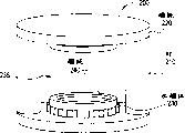
Fig. 2 has described the perspective view of known permanent magnet.
Fig. 3 described with Fig. 2 in the lateral elevational view of similar known permanent magnet, be used to illustrate magnetic flux path.
Fig. 4 described with Fig. 2 and 3 in the upper plane figure of similar known permanent magnet, be used to illustrate magnetic flux path.
Fig. 5 described according to specific embodiments of the invention regulate be used for permanent MRI magnetic field generator (with describe at Fig. 1 similar) the high level flow chart of method of magnetic center field.
Fig. 6 described according to specific embodiments of the invention regulate be used for permanent MRI magnetic field generator (with describe at Fig. 1 similar) the detail flowchart of method of magnetic center field.
Fig. 7 has illustrated the perspective view according to the permanent magnet with the sept in the yoke of being formed at of various embodiment of the present invention.
Fig. 8 has described and the upper plane figure that similarly has the permanent magnet of the groove that cuts or form in yoke shown in Figure 7, and has described the magnetic flux path according to various embodiment of the present invention.
Along with reading in conjunction with the accompanying drawings, can better understand the top general introduction and the following detailed of specific embodiments of the invention.Yet, be appreciated that the present invention is not subjected to the restriction of setting illustrated in the accompanying drawings and structure.
The specific embodiment
Embodiments of the invention relate to the magnetic field generator that is used for MRI.More specifically, the present invention relates to be used to regulate the magnetic center field system and method, be used to combine the magnetic field generator of the MRI of permanent magnet.At least one embodiment relates to the magnetic center field of using Machine Design to regulate the imaging volume that is used for the MRI magnetic field generator.
Fig. 1 has described generally with the MR imaging apparatus of 100 labellings or some critical pieces and the several main interconnective schematic statement of MRI.The assembly of describing on the top of Fig. 1 comprises that generally with the imaging device of 105 labellings, it can be arranged in the scanning room.Magnet 114 produces the B that is used for image forming program
0Magnetic field.In at least one embodiment, gradient coil 112 is included in the magnet 114, to be created on X, Y, the Z direction at B
0Gradient in the magnetic field.In this embodiment, RF coil 110 is positioned at gradient coil 112 inside.RF coil 110 produces with 90o or the necessary B of 180o rotation spin
1Magnetic field.RF coil 110 also can detect the signal from the spin of inside of human body.
In at least one embodiment, patient is positioned at the inside of magnet 114.Preferably, the scanning room by the RF shading ring around, to prevent high-power RF impulse radiation surrounding.This RF shielding for example also can stop the external RF signals from TV and broadcasting station to enter the scanning room, and is detected by imaging device 115.The scanning room that has also can by ring shielding magnetism around, described magnetic field is sealed in this magnetic shield.
In at least one embodiment, imaging device 115 comprises computer or CPU 120, wherein all components of CPU 120 control imaging devices 115.RF assembly under CPU control comprises radio frequency source and pulse programmer 130 and 128 respectively.Source 130 produces the sine wave of expected frequency.Pulse programmer 128 makes the RF shaping pulse for becoming the sine pulse of mark.RF amplifier 126 increases to pulse power kilowatt by milliwatt.CPU120 also controls gradient pulse programmable device 118, and it is provided with each shape and amplitude of three gradient magnetics.Gradient amplifier 116 increases to the level that is enough to drive gradient coil with the power of gradient pulse.
In at least one embodiment, keyboard, mouse or other control systems provide to the input of CPU 120.Select and the customized image sequence from control station.Image can be shown in the display device, stores or is copied on the film.
Be appreciated that magnet 114 is the most expensive assemblies of magnetic resonance imaging system among the embodiment that describes here.(note: what we described in this application is permanent magnet, is not superconducting magnet).
As before providing, gradient coil 112 is created in B
0Gradient in the magnetic field.Gradient coil is the coil that remains on room temperature, because their structure produces the gradient of expectation.With respect to the patient slit between the magnetic pole of upper and lower gradient coil is described.
The magnetic resonance coordinate system of tentative standard uses anti-helmholtz type coil can be created in B on the Z direction
0In gradient.Electric current in two coils flows with relative direction, is created in two magnetic field gradients between the coil.In the B at coil place magnetic field superposition in B
0Magnetic field is simultaneously from B
0Magnetic field deducts the B magnetic field at the center of another coil.
Can be created in B by the coil among a pair of Fig. 8
0X in the magnetic field and Y gradient.Because by the sense of current of coil, the X-axis of Fig. 8 coil is created in B on the directions X
0Gradient in the magnetic field.The Y-axis of Fig. 8 coil provides along Y-axis at B
0Similar gradient in the magnetic field.
Embodiments of the invention relate to the magnetic field generator that is used for MRI.More specifically, embodiments of the invention relate to the method that is used to regulate central magnetic field, are used to combine the magnetic field generator of the MRI of permanent magnet.At least one embodiment of the present invention relates to the method that is adjusted in the magnetic field in the imaging volume that uses in the MRI magnetic field generator that has used Machine Design.
Fig. 2-4 has described the embodiment that is used for known permanent magnet system in the similar MRI medical treatment device that Fig. 1 describes.Concrete, Fig. 2 has described totally the perspective view with the known permanent magnetic field generator system of 200 labellings.
In the embodiment that describes, permanent magnet systems 200 comprises one or more assemblies, comprise in opposite directions post 210 (for example, ferrum or steel column), yoke in opposite directions 220 (for example, ferrum or steel yoke), permanent magnet in opposite directions 230 (for example NdFeB) and magnetic pole in opposite directions 240.In this embodiment, an air-gap 235 is shown between magnetic pole 240 and permanent magnet 230.Be appreciated that why only these four assemblies and a slit are shown, can imagine a plurality of or different structure and slits.Further the imagination can be made this assembly (just post, yoke and magnetic pole) by identical or different material.
Fig. 3 has described the front elevation view with similar known permanent magnet systems in Fig. 2.Fig. 3 has described the permanent magnet systems 300 of the post 310, yoke in opposite directions 320, permanent magnet in opposite directions 330, air-gap 235 and the magnetic pole 340 that comprise in opposite directions.Fig. 3 further illustrates magnetic flux path or loop 350 and 360.
Fig. 4 has described the upper plane figure with similar known permanent magnet systems 400 in Fig. 2 and 3.Fig. 4 has described yoke 420 and magnetic flux path 450 and 460.In the embodiment that describes, magnetic flux is shown center 454 from yoke 450 towards holding 454 and 456 outwards to flow out in opposite directions.Be understandable that at least one embodiment, magnetic flux will flow with opposite direction on yoke in opposite directions as described in Figure 3.
In order to understand permanent magnet, liken permanent magnet systems to circuit.Permanent magnet is equivalent to the power supply of circuit, and yoke, post and magnetic pole are equivalent to the electric conductor with little impedance.Yet, between the magnetic pole of flux circuit inside or other positions, there is the air gap, it has big impedance.Therefore, be appreciated that the electric current and voltage that central magnetic field intensity is equivalent to big impedance air-gap two ends flows.
Like this, for fixed system (system that just has fixed magnets), how depending on of central magnetic field strictness produces flux circuit, and if any, the air-gap of between the magnetic pole and inside, loop.Change or revise air-gap and can change central magnetic field.
Can infer, in one embodiment, by inserting, increase and move adjustable steel plate (for example between pole piece),, can regulate or change the magnetic flux flows in permanent magnet systems to change or to be modified in the air gap in the magnetic loop.Change or be adjusted at air-gap in the magnetic loop and increase or reduced magnetoimpedance in selected (with more sensitive) zone, thereby regulate central magnetic field.
Fig. 5 described according to specific embodiments of the invention regulate be used for permanent MRI magnetic field generator (with describe at Fig. 1 similar) the high level flow chart of method of magnetic center field, this method is totally represented with 500.In at least one embodiment, method 500 comprises step 510, this step comprises the adjusting of determining the central magnetic field needs, step 520 comprises adjusting, revises, changes and/or utilizes at least one sept to regulate central magnetic field, wherein, in one embodiment, sept comprises at least one groove and/or insert.
Fig. 6 described according to specific embodiments of the invention regulate be used for permanent MRI magnetic field generator (with describe at Fig. 1 similar) the detail flowchart of method of magnetic center field, this method is represented with 600 generally.In at least one embodiment, method 600 comprises step 610, and this step comprises the adjusting of determining the central magnetic field needs.
Fig. 7 and Fig. 8 have described according to the slotted permanent magnet of tool of the present invention.Concrete, Fig. 7 has illustrated according to various embodiment of the present invention generally with the perspective view of the permanent-magnetic field generation systems of 700 expressions.In the embodiment that describes, permanent-magnetic field generation systems 700 comprises post 710 (for example ferrum or steel binding post), yoke in opposite directions 720 (for example ferrum or steel yoke), permanent magnet in opposite directions 730 (for example NdFeB) and magnetic pole in opposite directions 740 in opposite directions.In this embodiment, between magnetic pole 740, has air-gap 735.
In at least one embodiment of the present invention, formation has the yoke 720 of at least one sept 772, and this sept 772 is included at least one groove 770 that wherein forms or cut, and does not influence the globality of the frame for movement of yoke.Although be appreciated that a groove 770 only has been discussed, a plurality of grooves can be infered.For example, can on the end in opposite directions of yoke 720 in opposite directions, form eight grooves 770 (in Fig. 7, only having described seven grooves).Also can infer on the end of a yoke, on the two ends of a yoke, on the end of two yokes or form the groove 770 of symmetry or asymmetric pattern on the two ends of two yokes.Further can infer one or more grooves can be different size and/or shapes.
In one embodiment, sept 772 further comprise with a yoke 720 at least one groove 770 related or all or part of at least insertion at least one plate 774 wherein.In one embodiment, plate 774 is got in touch with the only groove 770 that only forms on an end of yoke in opposite directions.Yet in other embodiments, surpassing a plate 774 can get in touch with surpassing a groove, and wherein plate 770 is identical or different sizes, identical or different shape, or identical or different quantity.
For example, what the plate 774 that is used in combination with groove 770 on a yoke 770 can be than on another yoke is many, or the plate 774 on yoke can or take different shapes greater than the plate on another yoke.Form sept 772 and increase or influence the amount of air-gap by producing new air-gap or increase air gap amount or area (for example by removing one or more plates 774).Produce or increase the conscious modification of amount of air gap and changed one or more flux circuits, change or revise the central magnetic field of permanent magnet systems like this.
Fig. 3 and 4 has been provided by the magnetic flux as the typical permanent magnet that before provided.Be appreciated that from one or more yokes and remove one or more plates or sept, change or increase one or more air-gaps, thus influence or modification magnetic flux path or loop.The path of describing is mainly followed in magnetic flux or loop in Fig. 3, yet, the main difference of the magnetic flux path on the steel yoke has been described in Fig. 8.
Fig. 8 has described permanent magnet 800, and it has the yoke 820 that is provided in four grooves 870 that wherein form.In this embodiment, groove 870 (use plate or do not use plate) influences or revises magnetic flux 850 and 860 as shown.Just, at least in this embodiment, magnetic flux path is attempted to flow around groove 870.Be appreciated that the difference by the magnetic flux between Fig. 2 and Fig. 8, groove 870 can influence central magnetic field as described above (for example as many as 76 Gausses).In the embodiment that describes, for example can use the steel plate of 5 centimetres of 2 cm x to produce air-gap.
Can expect to revise structure, comprise and widen air-gap and/or the chosen position place on yoke increases a plurality of grooves, can change field intensity.Also can expect to use different material (for example different steel), also can revise regulating power with different magnetic characteristics.For example, can use the C1020 steel to replace C1006 steel or other metals.
Usually, the magnetic field intensity of assembling MRI system is successive.Be provided for regulating the magnetic field intensity of MRI system, make the magnetic field can be according to the meticulous rotation of expectation, because can the control interval thing insert to be used for part by design.Further use the sept of different materials, for example short steel sept or use different materials, or other combination.
Can expect that for the magnetic system that is used for MRI, not only central field must satisfy concrete field window, and magnetic field will have high field homogeneity (just, or low resonance).In at least one embodiment, can sept be added on the yoke with symmetric form.Just sept can be added to top and bottom, left side and right side and/or front and back.Can be with the conscious installation steel plate of asymmetric form to reduce or to eliminate concrete resonance.For example, be higher than the magnetic field intensity at the one side place, top in the imaging volume, the steel sept can be added into the top yoke to regulate central field and resonance if determine magnetic field intensity at the one side place, bottom of MRI system.For example, in the magnetic system with 0.215 tesla's central field, if sept is added to the top yoke, the net effect on the central magnetic field is 55 gaussian sum 3400ppm with the Z1 gradient of crossing 40 cm diameter spheroids.Can further regulate the concrete amount of the field imbalance between left side and the right side, and be used for the volumetrical front and back of imaging one side.
One or more embodiment of the present invention supports the bigger regulating power of magnetic center field, can be accurately with the position adjustments of the permanent magnet of assembling to magnetic center to satisfy design specification.
At least one embodiment can be suitable for the different magnetic system that matches.Can regulate one or more regulating powers to be used to use the different system of one or more forms, for example, sept (just groove and/or plate) size, sept shape, spacer material, number of spacers and sept position (just, middle or at one or whole two ends of yokes).Expect that also the symmetrical pattern of a relative end of on the only one or both ends of yoke in opposite directions sept or any one or two yokes can regulate the magnetic center field deformation.For example, be desirably in one in opposite directions in the end of yoke, one in opposite directions in the two ends of yoke, in the same end of different yokes in opposite directions or form the symmetrical pattern of sept in the different ends of different yoke in opposite directions.Further expect at one end or can repeat identical or different symmetric pattern on the yoke, or on different or yoke, form different patterns.Further the whole sept of expectation can be identical or different size, shape and/or material.
Further expect when correct the use, on front portion, back and/or a side of magnetic system, use sept that the field resonance regulating power of specified level can be provided.The asymmetric pattern (just groove and/or plate) that further can use conscious sept is to eliminate concrete field resonance.For example, expect one in opposite directions in the end of yoke, one in opposite directions in the two ends of yoke, in the same end of different yokes in opposite directions or form the symmetrical pattern of sept in the different ends of different yoke in opposite directions.Further expectation can be used at one end or multiple different asymmetric pattern in yoke place or asymmetric pattern.Expect that further whole septs can be identical or different size, shape and/or materials.
Although describe the present invention with reference to the accompanying drawings, be appreciated that those skilled in the art can carry out various modifications and replacement of equal value, as long as it does not break away from spirit of the present invention.Can make amendment in addition to be suitable for concrete situation and the material that the present invention provides, as long as it does not break away from spirit of the present invention.Therefore, the present invention is not subjected to the restriction of the specific embodiment that provides above, and the present invention will comprise whole embodiment of the scope that falls into claims.
Claims (10)
1, have the magnetic field generator system (700,800) of magnetic center field, this generator system (700,800) comprising:
Post in opposite directions (710);
Be connected to the yoke in opposite directions (720,780) of described post (710) in opposite directions, at least one described post (710) has sept (772);
At least one permanent magnet (730) is connected at least one described yoke (720,780) in opposite directions;
And
At least one sept (772) that at least one described post (710), described yoke (720,780) and described permanent magnet (730), forms.
2, the system of claim 1 (700,800), wherein said at least one sept (772) is included at least one groove (770,870) that forms at least one described yoke (720,780).
3, the system of claim 2 (700,800), wherein said at least one sept (772) is included at least one groove (770,870) that forms in the end in opposite directions of at least one described groove in opposite directions.
4, the system of claim 2 (700,800), wherein said sept (772) is included at least one groove (770,870) that forms in each described yoke (720,780).
5, the system of claim 2 (700,800), wherein said sept (772) is included in a plurality of grooves (770,870) that form at least one described yoke (720,780).
6, the system of claim 5 (700,800), wherein said sept (772) is included in the symmetrical pattern of the groove (770,870) that forms at least one described yoke (720,780).
7, the system of claim 5 (700,800), wherein said sept (772) is included in the asymmetric pattern of the groove (770,870) that forms at least one described yoke (720,780).
8, the system of claim 5 (700,800), at least two in wherein said a plurality of grooves (770,870) is different sizes.
9, be used to regulate the method (500,600) of the magnetic center field of permanent magnet systems (700,800), described method comprises:
Determine the adjusting that magnetic center field (510,610) needs; And
Regulate magnetic center field (520,620) by in permanent magnet systems (700,800), using at least one sept (772).
10, the method for claim 9 (500,600), wherein said sept (772) are included in and form at least one groove (770,870) in the permanent magnet systems (700,800).
Applications Claiming Priority (2)
| Application Number | Priority Date | Filing Date | Title |
|---|---|---|---|
| US10/686972 | 2003-10-16 | ||
| US10/686,972 US6809619B1 (en) | 2003-10-16 | 2003-10-16 | System and method for adjusting magnetic center field for permanent MRI magnetic field generator |
Publications (1)
| Publication Number | Publication Date |
|---|---|
| CN1611187A true CN1611187A (en) | 2005-05-04 |
Family
ID=33160043
Family Applications (1)
| Application Number | Title | Priority Date | Filing Date |
|---|---|---|---|
| CN200410087447.3A Pending CN1611187A (en) | 2003-10-16 | 2004-10-15 | System and method for adjusting magnetic center field for permanent MRI magnetic field generator |
Country Status (4)
| Country | Link |
|---|---|
| US (1) | US6809619B1 (en) |
| EP (1) | EP1524531A3 (en) |
| JP (1) | JP2005118566A (en) |
| CN (1) | CN1611187A (en) |
Families Citing this family (9)
| Publication number | Priority date | Publication date | Assignee | Title |
|---|---|---|---|---|
| CN100581454C (en) * | 2006-07-14 | 2010-01-20 | Ge医疗系统环球技术有限公司 | Magnetic field generator and MRI device |
| TW200817669A (en) * | 2006-10-14 | 2008-04-16 | Univ Nat Central | Non-destructive testing method for a reinforcing bar and device thereof |
| US9135686B2 (en) * | 2006-10-25 | 2015-09-15 | The Invention Science Fund I Llc | Distorting feature compensating |
| US7873234B2 (en) * | 2006-11-09 | 2011-01-18 | The Invention Science Fund I, Llc | Input compensating for imaging distortion |
| US8041145B2 (en) | 2006-11-17 | 2011-10-18 | The Invention Science Fund I, Llc | Distortion compensated imaging |
| US7667462B2 (en) * | 2006-12-22 | 2010-02-23 | Schlumberger Technology Corporation | Nuclear magnetic resonance module |
| JP5535139B2 (en) * | 2011-06-30 | 2014-07-02 | 株式会社ヴァレオジャパン | Proximity sensor |
| MX2017002939A (en) * | 2014-09-05 | 2017-12-07 | Hyperfine Res Inc | Automatic configuration of a low field magnetic resonance imaging system. |
| US10539637B2 (en) | 2016-11-22 | 2020-01-21 | Hyperfine Research, Inc. | Portable magnetic resonance imaging methods and apparatus |
Family Cites Families (6)
| Publication number | Priority date | Publication date | Assignee | Title |
|---|---|---|---|---|
| JPS60239005A (en) * | 1984-05-11 | 1985-11-27 | Sumitomo Special Metals Co Ltd | Magnetic field generating device |
| US4943774A (en) * | 1989-06-01 | 1990-07-24 | General Atomics | Magnetic field control apparatus |
| EP1647831B1 (en) * | 1996-10-30 | 2008-12-03 | Hitachi Medical Corporation | Open superconducting magnet apparatus |
| JP2953659B1 (en) * | 1998-08-06 | 1999-09-27 | 住友特殊金属株式会社 | Magnetic field generator for MRI, method of assembling the same, and method of assembling magnet unit used therein |
| US6448772B1 (en) * | 2000-10-06 | 2002-09-10 | Sumitomo Special Metals Co., Ltd. | Magnetic field adjusting apparatus, magnetic field adjusting method and recording medium |
| JP2003024296A (en) * | 2001-07-04 | 2003-01-28 | Ge Medical Systems Global Technology Co Llc | Static magnetic field adjusting method and mri equipment |
-
2003
- 2003-10-16 US US10/686,972 patent/US6809619B1/en not_active Expired - Lifetime
-
2004
- 2004-10-14 EP EP04256350A patent/EP1524531A3/en not_active Withdrawn
- 2004-10-15 CN CN200410087447.3A patent/CN1611187A/en active Pending
- 2004-10-15 JP JP2004300863A patent/JP2005118566A/en not_active Withdrawn
Also Published As
| Publication number | Publication date |
|---|---|
| EP1524531A3 (en) | 2005-06-15 |
| JP2005118566A (en) | 2005-05-12 |
| EP1524531A2 (en) | 2005-04-20 |
| US6809619B1 (en) | 2004-10-26 |
Similar Documents
| Publication | Publication Date | Title |
|---|---|---|
| JP6693987B2 (en) | Permanent magnet arrangement for an MR arrangement with axially and laterally displaceable and rotatably mounted ring module | |
| JP2839114B2 (en) | Permanent magnet for nuclear magnetic resonance imaging equipment | |
| JP2978873B2 (en) | Electromagnet and accelerator, and accelerator system | |
| US9055662B2 (en) | Cyclotron comprising a means for modifying the magnetic field profile and associated method | |
| EP1018036A1 (en) | Magnetic apparatus for mri | |
| US20110248715A1 (en) | Compact Inhomogeneous Permanent Magnetic Field Generator for Magnetic Resonance Imaging | |
| JPH021238A (en) | Magnetic field gradient coil apparatus and magnetic resonance imaging system using the same | |
| CN1611187A (en) | System and method for adjusting magnetic center field for permanent MRI magnetic field generator | |
| CN207802493U (en) | Petal-shaped accelerator and its c-type connector motor magnet | |
| CN1702473B (en) | Method for controlling static magnetic field and MRI apparatus | |
| WO2021119109A2 (en) | Swaged component magnet assembly for magnetic resonance imaging | |
| EP1389733B1 (en) | Shimming an MRI magnet assembly | |
| CN100504432C (en) | Magnetostatic field regulating method in magnetic resonance equipment and magnetostatic field generating apparatus thereof | |
| CN1500441A (en) | Static magnetic field generating apparatus and magnetic resonance imaging apparatus | |
| CN209343875U (en) | Magnet apparatus and MR imaging apparatus | |
| CN1508560A (en) | C-type open MRI panel radio-frequency coil | |
| Varfolomeev et al. | Performance of the undulator for the FOM-FEM project | |
| CN1486672A (en) | Magnetic field correcting method, megnetic field generating equipment and magnetic resonance imaging equipment | |
| CN210119557U (en) | Permanent magnetic field generating device and magnetic resonance imaging equipment | |
| JP4000555B2 (en) | Periodic magnetic field generator | |
| JPS6343304A (en) | Uniform field magnet of permanent magnet type | |
| JP3189973B2 (en) | Magnetic resonance imaging equipment | |
| Peng et al. | Construction and tuning of BEPC mini-β permanent quadrupole prototype | |
| JPH10149915A (en) | Field generating magnet for magnetron plasma | |
| JPH0371891B2 (en) |
Legal Events
| Date | Code | Title | Description |
|---|---|---|---|
| C06 | Publication | ||
| PB01 | Publication | ||
| C10 | Entry into substantive examination | ||
| SE01 | Entry into force of request for substantive examination | ||
| C02 | Deemed withdrawal of patent application after publication (patent law 2001) | ||
| WD01 | Invention patent application deemed withdrawn after publication |