CN1609552B - Method for measuring curved surface of a workpiece - Google Patents
Method for measuring curved surface of a workpiece Download PDFInfo
- Publication number
- CN1609552B CN1609552B CN2004100837652A CN200410083765A CN1609552B CN 1609552 B CN1609552 B CN 1609552B CN 2004100837652 A CN2004100837652 A CN 2004100837652A CN 200410083765 A CN200410083765 A CN 200410083765A CN 1609552 B CN1609552 B CN 1609552B
- Authority
- CN
- China
- Prior art keywords
- aforementioned
- workpiece
- coordinate system
- measurement range
- coordinate
- Prior art date
- Legal status (The legal status is an assumption and is not a legal conclusion. Google has not performed a legal analysis and makes no representation as to the accuracy of the status listed.)
- Expired - Fee Related
Links
Images


Classifications
-
- G—PHYSICS
- G01—MEASURING; TESTING
- G01B—MEASURING LENGTH, THICKNESS OR SIMILAR LINEAR DIMENSIONS; MEASURING ANGLES; MEASURING AREAS; MEASURING IRREGULARITIES OF SURFACES OR CONTOURS
- G01B21/00—Measuring arrangements or details thereof, where the measuring technique is not covered by the other groups of this subclass, unspecified or not relevant
- G01B21/02—Measuring arrangements or details thereof, where the measuring technique is not covered by the other groups of this subclass, unspecified or not relevant for measuring length, width, or thickness
- G01B21/04—Measuring arrangements or details thereof, where the measuring technique is not covered by the other groups of this subclass, unspecified or not relevant for measuring length, width, or thickness by measuring coordinates of points
Landscapes
- Physics & Mathematics (AREA)
- General Physics & Mathematics (AREA)
- A Measuring Device Byusing Mechanical Method (AREA)
- Length Measuring Devices With Unspecified Measuring Means (AREA)
Abstract
A theoretical expression of a workpiece (W) the curved surface of which is measured by a measuring probe (110) equipped with a stylus (111) is specified, a measuring area where the measurement is executed on the measuring surface of the workpiece (W) is determined, and the axis angles of the stylus (111) are determined based on the coordinate values and the normal vector of a representative pointdetermined in the measuring area.
Description
Technical field
The present invention relates to the measuring method of curve surface of workpiece, particularly workpiece and gauge head do not produce the interference measuring method of measuring workpieces curved surface like that.
Background technology
Workpiece with curved surface has various types, but the processing of these curved surfaces is mostly difficult, therefore just needs the high-acruracy survey of curve surface of workpiece.
Representational workpiece with such curved surface has gear, especially on the final reduction gear of motor vehicle etc. etc., as changing the gear that the axial transmission that makes rotary motive power simultaneously of its revolution is slowed down, the gears that use the flank of tooth that has spiral bevel gear or form with the curved surface of hypoid gear etc. more.
Spiral bevel gear as shown in figure 20, is that gear wheel (gear) and pinion wheel (pinion wheel) mesh the structure that the axis of two gears intersects at grade.
In contrast, hypoid gear possesses gear wheel (ring gear) and pinion wheel (pinion wheel) engagement, but the axis of two gears does not intersect at grade, have on the so-called biasing this point, except the degree of freedom of the configuration in the space of power conveying system high and, compare with spiral bevel gear, can make level and smooth more and the running that can solemn silence of revolution, the characteristics that the intensity of tooth can be bigger.
These gears are considered from the transmission of power aspect, are necessary to prevent wearing and tearing and prevent to produce noise, and the high-precision processing of inevitable requirement, its result needs high-precision measuring method.
, owing to form with curved surface on teeth directional and tooth depth direction, there is processing in the flank of tooth of these gears and measures all problems of difficulty.
For example, the ring gear of the hypoid gear of representing with the basic parameter of Figure 21 carries out cutting processing according to theoretic cutting parameter shown in Figure 22 by gear cutting machine.For pinion wheel too, but under this intact situation, because the error of the machinery of gear cutting machine, differing obtains showing the gear mesh of good gear contact surely.
Therefore, the toe joint that carries out repeatedly observing as the mutual contact vestige of the flank of tooth on one side touches, on one side carry out trial cut tooth (limit is revised cutting parameter limit and adjusted cutting) repeatedly, obtain showing the gear mesh that the good toe joint as final goal touches according to in-situ processing person's experience and exploration.This is called as the exploitation of gear teeth contact.
If can from the gear that obtains like this, learn conversely and carry out which kind of exploitation (which kind of cutting parameter has been carried out correction how), just can avoid the influence of the error of the machinery that on each gear cutting machine, exists.From such purpose, studied the deduction method of cutting parameter.
The example of ooth-cutting tprinciple of the ring gear of hypoid gear is described by Figure 23.
The cutter 1 of gear cutting machine with cutter shaft zc be the center pivotally the axle be bearing on the reel cage 2.
On the other hand, as the ring gear blank of workpiece W, axle is bearing on the shaking tray 3 pivotally, but during a tooth of cutting, workpiece is not fixed pivotally.
Coordinate system among this Figure 23, having with machine center Om is initial point, with reel cage axle (zm axle), H axle (ym axle), V axle (by initial point Om and with reel cage axle (zm axle) axle vertical with the H axle: the coordinate system of machine of Gou Chenging and the be initial point xm axle) with center cutter Oc, with the tool coordinate system (with reference to Figure 25) of xc axle, yc axle, zc axle formation.
In addition, for workpiece W, having with gear centre Og is initial point, with the gear coordinate system (with reference to Figure 25) of xg axle, yg axle, zg axle formation.
At this, generally be that workpiece spindle zg and reel cage axle zm are in the same plane, machine center Om is consistent with gear centre Og.
The mutual relationship of each coordinate system in the VH plane, as shown in figure 24, the amount of bias of V axle (xm axle) and xc axle is Hg, the amount of bias of H axle (ym axle) and yc axle is Vg.At this, the sword face that Xgc represents cutter 1 is a position vector on the track of center when turning round with center cutter Oc.
The mutual relationship of each coordinate system on the ymzm plane, such as shown in figure 25.At this, the distance of (V axle) is represented with Lg from back of work Wb to gear centre Og, and machine dedendum angle (angle of the angle of ym axle and zg axle) is represented with λ gr.
Because such formation, when the cutting of the tooth of the workpiece W that is undertaken by cutter 1 finishes, after making cutter 1 stop revolution and leaving workpiece W, make workpiece W around zg axle revolution predetermined angular, make cutter 1 revolution again and make workpiece W return to cutting position, carry out the cutting of next tooth.Owing to carry out the cutting of whole teeth like this, be replicated on the workpiece W as the position vector Xgc of the rotary track of cutter 1.The cutting parameter of the workpiece W (ring gear) that is cut is like this followingly inferred like that.
The aforementioned flank of tooth of the gear that forms by a curve for a flank of tooth, theory of mechanisms record and narrate according to theoretic each cutting parameter (theoretic cutting parameter: C1, C2 ... cutting process Cn) and derive theoretical flank of tooth formula X (u, v, C1, C2 ... Cn).(at this, X represents vector, and u represents the angle of revolution of cutter 1, and v represents the distance from center cutter Oc to cutter sword face.)
The aforementioned flank of tooth of three-dimensional coordinate measurement also obtains measuring flank of tooth data M.(M is a vector)
At this, because for the individual measurement data Mi of I,
Mi=X(ui、vi、C1+ΔC1、C2+AC2、......Cn+ΔCn)......(1)
Set up, so the difference of the value that can provide aforementioned measurement flank of tooth data M with aforementioned theoretical flank of tooth formula X is obtained as residual error (M-X).(at this, Δ C1, Δ C2 ... Δ Cn represents the correction to the unknown of theoretic cutting parameter)
For j=1~n, can obtain that two of aforementioned residual error is taken advantage of and be the value of aforementioned cutting parameters C j+ Δ Cj hour and standard deviation at that time with least square method.
Search makes the aforementioned cutting parameters C k of aforesaid standards deviation minimum, Ck+ Δ Ck as cutting parametric inference value.
Obtain inferred value with aforementioned cutting parametric inference value Ck+ Δ Ck and to the cutting number beyond k by same processing, carry out this order more repeatedly, obtain whole cutting parametric inference values.
When the aforementioned flank of tooth of three-dimensional coordinate measurement, the coordinate system of the aforementioned theoretical flank of tooth formula Xg before the conversion is decided to be Og-xg, yg, zg, when the coordinate system of three-dimensional measuring machine is decided to be Ot-xt, yt, zt, make a coordinate axis (for example Z axial coordinate axle z t) of three-dimensional measuring machine consistent with gear shaft zg, (the coordinate origin Og of theoretical flank of tooth formula X) is consistent with the initial point Ot of three-dimensional measuring machine coordinate system for envoy's conical point.(because the track of sword face is replicated on the workpiece W, so can coordinate transform obtain theoretical flank of tooth formula Xg as the theoretical formula X of the track of sword end face.) (Xg is a vector.)
When the unknown angle that another coordinate axis (for example X-axis coordinate axis xg) of another coordinate axis of three-dimensional measuring machine (for example X-axis coordinate axis xt) and theoretical flank of tooth formula Xg is become was decided to be ψ, it was such to make the preceding theoretical flank of tooth formula Xg of conversion become following formula around the rotating result of zt axle by the transformation matrix of coordinates C (ψ) relevant with revolution.(C, X are vectors.)
Xt=C(ψ)Xg......(3)
According to this relation and since can by aforesaid method be added in cutting parametric inference value (C1+ Δ C1, C2+ Δ C2 ... Cn+ Δ Cn) go up and obtain angle ψ, so can carry out coordinate transform to the measurement coordinate system of theoretical flank of tooth formula.But, since ψ for whole cutting parameters (C1, C2 ... Cn) be in subordinate relation, so by connect equate can not separate C1, C2 ... the occasion of the total n+1 of a Cn and ψ unknown number, for (ψ and C1), (ψ and C2) ... each of n the combination of (ψ and Cn) is by the binary company upright solution of equation relevant with least square method.
; in the deduction method of this cutting parameter; need a plurality of places on the three-dimensional measurement flank of tooth to obtain measuring flank of tooth data M; but; because the workpiece flank of tooth formula in the workpiece coordinate system is unknown; so can not make parts program (part program), thereby have to carry out manual measurement.
The obstruction that this efficient that will become the cutting parametric inference improves, on the other hand, owing to measure for a long time, so the measurement environment condition changes because of people's body temperature by staff, force the size of workpiece W to change, produced the problem that to carry out high-acruracy survey.Even in the occasion of carrying out manual measurement, because the coordinate figure (theoretical value or actual value) of its measurement point is unknown, so be difficult to carry out the evaluation of workpiece.
Have again, using contacting signal probe or profiling gauge head to carry out the occasion of measurement of curved surface of workpiece of the flank of tooth etc. of cross helical gear because measurement face is a curve shape, thus exist the contact pilotage of gauge head or top spherical contact may with the problem of gear tooth interference.
Summary of the invention
Fundamental purpose of the present invention is, providing can safety and measure measuring method and the program and the medium of curve surface of workpiece of measuring point of the workpiece with curved surface of the flank of tooth etc. of cross helical gear accurately.
In order to reach aforementioned purpose, the measuring method of curve surface of workpiece of the present invention is characterized in that, has: acquisition is by the theoretical formula input step of the theoretical formula of the workpiece of the gauge head measurement curved surface with contact pilotage; Set measurement range setting step as the measurement range of the scope of on aforementioned curved surface, measuring; On aforementioned measurement range, set representative point, calculate the representative point calculation procedure of the coordinate figure and the normal vector of this representative point according to aforementioned theoretical formula; Calculate the tangent line vector of the face direction of the above-mentioned curved surface in the above-mentioned measurement range according to aforementioned normal vector, determine the axis angle deciding step of the face azimuth axis angle of aforementioned contact pilotage according to this tangent line vector by each aforementioned measurement range; And the axis angle of above-mentioned contact pilotage changed to the above-mentioned axis angle that determines is carried out the measurement of above-mentioned curved surface in above-mentioned measurement range scope measuring process.
At this, aforementioned theoretical formula also can be the measurement shape formula of resolving the result of measurement data.
In addition, aforementioned theoretical formula also can replace theoretical formula input according to calculating as the basic parameter of the design load of workpiece etc.
Have again, axis angle as aforementioned contact pilotage, also can calculate the tangent line vector of the curve surface of workpiece in the aforementioned measurement range according to aforementioned normal vector, calculate face azimuth axis angle according to this tangent line vector. this tangent line vector is the vector vertical with normal vector, can define a plurality of tangent line vectors. at this, representative comprises the face of these a plurality of tangent line vectors and is called the tangent line vector.
At this, so-called face azimuth axis angle is meant to be used for making tangent with the curve surface of workpiece of measurement range and to comprise the face angle parallel with the face of the axis that comprises contact pilotage of tangent line vector.
In addition, as the axis angle of aforementioned contact pilotage, also can calculate the tilt axis angle of aforementioned contact pilotage according to the workpiece shape of aforementioned measurement range.
In addition, measurement range also can be divided into the stated number that is predetermined, and in addition, also can judge the degree of crook of this measurement range and cut apart measurement range as required according to the interior angle angle of a plurality of normal vectors of measurement range.
At this, so-called interior angle angle is meant the little side of the intersecting angle a when normal or its extended line intersect with another normal or its extended line, in a normal or its extended line and another normal or the Uncrossed occasion of its extended line, be meant another normal is projected on the face that contains a normal the little side of the normal of this projection or its extended line and a normal or its extended line intersecting angle.
Have again, also can import the measuring condition that contains measuring machine information, make the measure portion program according to the information of this measuring condition and aforementioned theoretical formula and aforesaid axis angle.
In addition, when the measurement of reality, workpiece coordinate system that also can set basis workpiece mounting posture makes the theoretical coordinate system in the aforementioned theoretical formula consistent with this workpiece coordinate system.
Having, is different occasions at the theoretical coordinate of said workpiece coordinate system and aforementioned theoretical formula again, also can angular transformation becomes coordinate figure and axis angle in the said workpiece coordinate system with aforementioned axis the coordinate figure that calculates with aforementioned theoretical coordinate system.
In addition, preferably, aforementioned theoretical formula input step, has input according to the parameter input step of the basic parameter of the two-dimensional design figure of said workpiece with calculate the theoretical formula calculation procedure of the cube theory formula of said workpiece according to aforementioned basic parameter, aforementioned representative point calculation procedure is set aforementioned representative point according to aforementioned two-dimensional design figure with two-dimensional coordinate, calculates the D coordinates value and the normal vector of this representative point according to aforementioned cube theory formula.
At this, the coordinate system of aforementioned two-dimensional design figure, being not limited to rectangular coordinate system, also can be polar coordinate system etc., importantly, so long as the coordinate system that can record and narrate on two dimensional surface is just passable, the theoretical coordinate of cube theory formula system is not limited to rectangular coordinate system, if polar coordinate system etc. can the specified three-dimensional space coordinate system, no matter any coordinate system can, as long as it is just passable to design the coordinate system of the coordinate transform between coordinate system and the theoretical coordinate system.
Have again, preferably also have the design coordinate transform coefficient calculating step of the coordinate transform coefficient between the theoretical coordinate system of the design coordinate system that calculates aforementioned two-dimensional design figure and aforementioned cube theory formula.
According to the present invention, the contact pilotage axis angle of the gauge head when determining that owing to the theoretical formula based on workpiece carrying out curve surface of workpiece measures so gauge head and workpiece are not interfered, can be measured safely and easily.
In addition, owing to set representative point in measurement range, the axis angle of calculating contact pilotage according to the coordinate figure and the normal vector of this representative point is so can alleviate the load of computing.
Have again, because a plurality of representative points and synthetic each normal vector are set on the end of measurement range, so can improve the calculating fiduciary level of the axis angle in its measurement range.That is, if the axis angle of obtaining like this can be avoided the interference of workpiece and gauge head reliably.
In addition, owing to judge the possibility of interference of workpiece and gauge head, cut apart measurement range according to its result, so can avoid the interference of workpiece and gauge head more reliably by the interior angle angle of a plurality of normals of measurement range.
Have again, owing to determine the axis angle according to the shape of workpiece, so can avoid the interference of workpiece and gauge head more reliably.
In addition, because the theoretical formula according to workpiece can generate the measurement parts program that contains contact pilotage axis angle control command, even so before the machining of workpiece self, also can make the measurement parts program in advance, since workpiece processing is finished after the horse back can the hand measurement operation, so improved whole manufacturing efficient.
In addition, even have the workpiece of complicated curved surface, because gauge head and workpiece do not interfere and can generate the measurement parts program, so can improve the security of measuring operation and realize robotization easily.
Have again, because according on measurement range, having the cube theory formula of the workpiece of curved surface, can calculate the representative point on two-dimensional design figure, set or the D coordinates value and the normal vector of specified point, so even the D coordinates value on the object face that before workpiece processing finishes, also can obtain measuring.
Especially, because by using the coordinate transform coefficient, can easily calculate with the representative point of the aforementioned measurement range of two-dimensional coordinate appointment or the D coordinates value and the normal vector of specified point according to aforementioned two-dimensional design figure, become easy so measure making of parts program etc.
Description of drawings
Fig. 1 is the figure of the measuring system of expression the 1st embodiment of the present invention.
Fig. 2 is the calcspar of the measuring system of the 1st embodiment of the present invention.
Fig. 3 is the figure of the action of expression contacting signal probe.
Fig. 4 is the process flow diagram of the measuring sequence of expression the 1st embodiment of the present invention.
Fig. 5 is the process flow diagram of the details set of the coordinate system of expression the 1st embodiment of the present invention.
Fig. 6 is the stereographic map of the flank of tooth of ring gear.
Fig. 7 is the figure of explanation measurement range.
Fig. 8 is the figure of explanation interior angle angle.
Fig. 9 is the figure that the explanation measurement range is distributed.
Figure 10 is the figure of the angular relationship of expression workpiece and gauge head.
Figure 11 is the figure of explanation tangent line vector.
Figure 12 is the figure of expression method of representatives line vector.
Figure 13 is the figure that the tangent line vector is represented in expression.
Figure 14 is the figure of explanation tilt axis angle.
Figure 15 is the figure that the explanation coordinate system is set.
Figure 16 is another figure that the explanation coordinate system is set.
Figure 17 is the figure of the calculation element of expression the 2nd embodiment of the present invention.
Figure 18 is the figure of explanation two-dimensional design drawing.
Figure 19 is the figure of the specified point search in the explanation theoretical coordinate system.
Figure 20 is the figure of explanation spiral bevel gear.
Figure 21 is the figure of basic parameter example of the ring gear of explanation hypoid gear.
Figure 22 is the figure of cutting parameter example of the ring gear of explanation hypoid gear.
Figure 23 is the figure of an example of ooth-cutting tprinciple of the ring gear of explanation hypoid gear.
Figure 24 is the figure of the coordinate system in the cutting of ring gear of explanation hypoid gear.
Figure 25 is another figure of the coordinate system in the cutting of ring gear of explanation hypoid gear.
Embodiment
With reference to the accompanying drawings the preferred embodiments of the present invention are described below.
[embodiment 1]
Fig. 1 represents to implement with three-dimensional measuring machine the 1st embodiment of the measuring method of curve surface of workpiece of the present invention, and three-dimensional measuring machine 100 constitutes measuring system 10 by control device 200 and computing machine 300.
Three-dimensional measuring machine 100 has the column 102 that is erected at the two ends that uprightly are arranged at surveying work platform 101 and the X-axis crossbeam 104 between the pillar 103.Also have by air bearing be bearing on this X-axis crossbeam 104 be bearing at X-axis slide block 106 (X-axis travel mechanism) that X-direction can move with by air bearing on this X-axis slide block 106 at Z axle center axle 107 (Z axle travel mechanism) that Z-direction can move.Because column 102 and pillar 103 are also by the air bearing supporting and from surveying work platform 101 come-ups, column 102 is led on Y direction by air bearing by the Y-axis guiding mechanism on the end that is arranged on surveying work platform 101 105, so column 102 and pillar 103 become one and can move (y-axis shift actuation mechanism) on Y direction.
X-axis slide block 106, column 102 and pillar 103, Z axle center axle 107 can be by linear scale detection amount of movements separately.At this, X-axis, Y-axis, Z axle are in orthogonal relation.
Lower end at Z axle center axle 107 is provided with contacting signal probe 110, and spherical contact 112 is set on the top of its contact pilotage 111.
Mounting workpiece W (ring gear of hypoid gear) on surveying work platform 101, contact with its flank of tooth Wt by the spherical contact 112 that makes contacting signal probe and to export activation signal, the amount of movement that reads each travel mechanism of its moment from linear scale is output as measurement data.
Fig. 2 represents the block scheme of major part of the electric unit of measuring system 10.
On three-dimensional measuring machine 100, have electric motor driven X-axis driving mechanism 121, Y-axis driving mechanism 122 and Z axle driving mechanism 123, drive X-axis slide block 106, column 102 and Z axle center axle 107 respectively.The amount of movement of these each slide block is detected by X-axis scale 124, Y-axis scale 125 and Z axle scale 126.
In control device 200, be provided with the motor that drives X-axis driving mechanism 121 X-axis driving circuit 201, drive Y-axis driving mechanism 122 motor Y-axis driving circuit 202 and drive the Z axle driving circuit 203 of the motor of Z axle driving mechanism 123.The scale of each of three-dimensional measuring machine 100 is connected with X-axis counter 204, Y-axis counter 205 and Z axle counter 206, the amount of movement of each slide block by these each counter count, by the activation signal S that generates in the activation signal generative circuit 116 of contacting signal probe 110, each count value D (xi, yi, zi) exports as measurement data with it simultaneously.
Contacting signal probe 110 has activation signal generative circuit 116 and axis drive mechanism 117, and as shown in Figure 3, with respect to the axis 114 of the gauge head body 113 of contacting signal probe 110, the axis 115 of contact pilotage 111 can tilt to any direction.More particularly, axis drive mechanism 117 is made of vertical bank driving mechanism and horizontal rotation driving mechanism, this vertical bank driving mechanism drives, so that the axis 115 of contact pilotage 111 is with respect to 114 arbitrarily angled θ v of inclination of axis of gauge head body 113, this horizontal rotation driving mechanism drives, so that the axis 115 of contact pilotage 111 only turns round arbitrarily angled θ h in the plane vertical with the axis 114 of gauge head body 113.
This axis drive mechanism 117 is driven by the axis drives circuit 225 of control device 200.
Computing machine 300 each driving circuit 201-203 of control and axis drives circuit 225 are imported each count value D (xi, yi, zi) simultaneously as measuring flank of tooth data M i.
In computing machine 300, have not shown various input-output units (keyboard, mouse, display, printer, circuit input-output unit, auxilary unit etc.), carry out various input-output operations and computing result's demonstration or printing etc. according to purpose.
Fig. 4 is the process flow diagram of the processing sequence when being illustrated in the computing machine 300 measuring method of carrying out curve surface of workpiece of the present invention, and as workpiece, the occasion of measuring with the flank of tooth of the ring gear that carries out hypoid gear is that example describes.
At first, begin the execution of the measuring method of curve surface of workpiece by S10.
Then, in S20, according to input basic parameters such as the design drawing of workpiece W (gear) (for example, Figure 21) and the cutting parameter (for example, Figure 22).At this, the cutting parameter also can be from theoretical value or measure the inferred value of result's deduction of actual gear.
Next, in S30, calculate the theoretical formula of gear teeth face according to basic parameter and cutting parameter.Process according to the cutting of the cutting parameter of theoretic cutting parameter or deduction be recorded and narrated and be calculated to theoretical formula can from theory of mechanisms, and for example, the flank of tooth Xg of the ring gear of hypoid gear and the normal for tooth surface Ng of unit can obtain as following.
Xg(u,v)=A-1(λgr+π/2){Xgc(u,v)+Dg)......(4)
Ng(u,v)=A-1(λgr+π/2)Ngc(u)......(5)
At this, Xg, A (about around the rotating transformation matrix of coordinates of xm axle), Xgc (position vector on the cutter sword face), Dg (position of the center cutter Oc among the coordinate system Om of gear cutting machine), Ngc (unit normal on the cutter sword face) are vectors.U represents the angle of revolution of cutter 1, and v represents the distance from center cutter Oc to cutter sword face.λ gr represents machine dedendum angle (coning angle at the bottom of the tooth) (with reference to Figure 25).
At this, each step constitution theory formula input step of S20, S30, but in the known occasion of theoretical formula, perhaps derive the occasion of shape formula from the analysis result of measurement data, also directly input hypothesis formula or shape formula, replace the theoretical formula calculated according to each parameters such as design loads, be used as theoretical formula in each step afterwards.
Below, in S40 according to theoretical formula setting measurement scope.
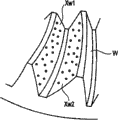
The flank of tooth Xw of workpiece W as shown in Figure 6, has right flank of tooth Xw2 and left flank of tooth Xw1, but because the order of handling is identical, so only the measurement of left flank of tooth Xw1 is described.
In the setting of measurement range, in the flank of tooth scope of left flank of tooth Xw1, set one or more measurement ranges An.This set algorithm can use various algorithms, at this, waits and cuts apart the teeth directional direction and come the setting measurement scope.Fig. 7 represents 1 flank of tooth Xw1, and the paper left side is the gear inboard, and the paper downside is a flank of tooth the lowest point side, measurement range A1, the A2 of expression bisection teeth directional direction.
Then, in S50, calculate the coordinate figure and the normal vector of the representative point of each measurement range.
Set algorithm as representative point has the whole bag of tricks, for example, in the occasion of prototype gear pitch, generally is to get a bit in the central authorities of measurement range, when carrying out the tooth surface shape measurement, generally is respectively to get a bit at the two ends of measurement range, amounts to 2 points.In the example of Fig. 7, on the tooth depth direction of the flank of tooth (flank of tooth from the direction of tooth bottom side) middle position to the tooth top side, two ends at each measurement range A1, A2 are provided with representative point Q11, Q12, Q21, Q22, calculate the coordinate figure and the normal vector of each representative point according to theoretical formula.
Next, in S60, calculate the interior angle θ i (with reference to Fig. 8) that normal vector N11, the N12 of representative point Q11, the Q12 of same measurement range (for example A1) intersect to form, test this interior angle angle θ i whether in predetermined angular, when this interior angle angle θ i≤predetermined angular, be judged as the flank of tooth crooked little of this measurement range.That is, can be judged as under the situation of the axis angle θ h that does not change contact pilotage, can carry out the measurement of this measurement range with identical axis angle θ h, this occasion makes processing to S80 branch and determine the axis angle of contact pilotage.
On the other hand, the occasion that surpasses predetermined angular at interior angle angle θ i, be judged as the flank of tooth crooked big of this measurement range. promptly, under the situation of the axis angle that does not change contact pilotage with identical axis angle θ h, in the occasion of measuring this measurement range, can be judged as and produce workpiece W and gauge head 110 possibility of interference, this occasion makes processing to S70 branch and cut apart measurement range.
Measurement range partitioning algorithm as S70 can use various algorithms, at this, uses the method for bisection teeth directional direction.Fig. 9 represents with this method measurement range A1 to be divided into the example of A11 and A12.
In S70, after having cut apart measurement range, make to handle to turn back to S50, calculate the coordinate figure and the normal vector of the representative point of each measurement range once more.
So, carry out cutting apart of measurement range repeatedly, become predetermined angular with till interior up to interior angle angle θ i.
In S80, when determining axis angle θ h, the θ v of contact pilotage 111, at first calculate tangent line vector Tw.For example, as shown in figure 10, if the tooth of gear is not have crooked straight-tooth, when the paper of figure was surface level, the axis angle θ h in the level of contact pilotage 111 can determine uniquely by measuring which flank of tooth.In contrast, in the occasion that is cross helical gear, for example, as shown in Figure 6, because bending is arranged on the flank of tooth, so need decide axis angle θ h according to the angle of bend of measurement range.
Therefore, as shown in figure 11, obtain the teeth directional direction tangent line vector Tw vertical, making tangent face (perpendicular to the face of the normal vector) angle parallel that comprises tangent line vector Tw simultaneously of curve surface of workpiece in its measurement range be decided to be face azimuth axis angle θ h with the face of the axis 115 that comprises contact pilotage 111 with the normal vector Nw of measurement range.
The method of calculating the tangent line vector based on normal vector has the whole bag of tricks, in measurement range, set the occasion of a plurality of representative points, the method of representatives line vector Nr that can calculate its measurement range with the normal vector of synthetic each representative point, ask the method (with reference to Figure 12) of representing tangent line vector Tr from this method of representatives line vector Nr, ask each tangent line vector from each normal vector, and synthetic each tangent line vector asks method arbitrary methods such as (with reference to Figure 13) of representing tangent line vector Tr to ask the tangent line vector.
Then, as shown in figure 14, in the occasion that the measurement face (teeth directional direction) of workpiece W tilts with respect to reference field, can be easily from machine dedendum angle λ gr decision tilt axis angle θ v (occasion of conical gear, tooth depth azimuth axis angle).That is, according to workpiece shape decision tilt axis angle θ v.
Have, (face azimuth axis angle θ h and tilt axis angle are v) by each measurement range decision for the axis angle again.
So, carried out the occasion of manual measurement after determining in the axis angle of each measurement range, by the specified measurement scope, axis drives circuit 225 control axis drive mechanism 117 also arrive θ h, θ v to the angular setting of the axis 115 of contact pilotage 111.In the occasion that does not have axis drives circuit 225 and axis drive mechanism 117, the angle of the axis 115 of manual adjustment contact pilotage 111 makes it to be shown as angle θ h, θ v on display.
Then, in A90, the input measurement condition.As this measuring condition, have kind (contacting signal probe/profiling gauge head), contact pilotage axis angle θ v, the θ h of the contacting signal probe 110 of use maximal value/control resolution, whether use the rotary table direction (left side/right side) etc. of the flank of tooth of diameter, backhaul distance (can change the distance of leaving workpiece W of the axis angle of contact pilotage 111 safely), the quantity of measuring the flank of tooth of kind (orientation measurements of pitch measurements/tooth surface shape measurement/a plurality of flank of tooth), measurement, the measurement of mounting workpiece W, the spherical contact 112 of gauge head pivotally.
Then in S100, generate and measure parts program.
Because axis angle θ h, the θ v of measurement range and the contact pilotage 111 that should adjust when measuring this measurement range determined, so can generate the measurement parts program of each measurement range according to measuring condition and theoretical formula (Xg, Ng).
Measure in the parts program at this, contain by adjust the contact pilotage axis angular setting order of the axis angle of contact pilotage 111 through axis drives circuit 225 control axis drive mechanism 117.
In addition and since with contacting signal probe during with the profiling gauge head measuring method different, so generate the measurement parts program corresponding (activation signal measurement parts program, profiling measure portion part etc.) with gauge head according to the gauge head that uses.
The measurement parts program of generation is carried out by the measurement parts program executive routines (not shown) that are stored in the computing machine 300, controls three-dimensional measuring machines 100 and export the measurement data of stipulating from control device 200 through control device 200.
Next, in S110, carry out being positioned on the three-dimensional measuring machine 100 to actual workpiece W and the setting of essential workpiece coordinate system when measuring.
The detailed process content of expression S110 in the process flow diagram of Fig. 5.
The measurement parts program that generates in S100 is set workpiece coordinate system with generate corresponding and when the measurement of the workpiece W of reality in theoretical coordinate system.Because this workpiece coordinate system and theoretical coordinate system are inconsistent usually,, perhaps each coordinate figure of measuring parts program is transformed into the workpiece coordinate value so be necessary to make two coordinate system unanimities.
Making workpiece coordinate system and the consistent occasion of theoretical coordinate system, in S220, make the coordinate system unanimity.
In contrast, preferably making the inconsistent occasion of coordinate system (for example, when being positioned on the three-dimensional measuring machine, because shape or the mounting posture of workpiece W, being difficult to intuitively to hold the occasion of theoretical coordinate system etc.), in S230, carry out coordinate transform to workpiece W.
In S210, carry out these branch process.Carry out any processing on earth, select by the operator usually.
In S220, in case the coordinate system O of three-dimensional measuring machine is set at after the workpiece coordinate system one or more of measuring workpieces W, the workpiece coordinate system interim temporarily according to its correction as a result.
Workpiece W mounting posture of mounting on surveying work platform 101 is arbitrarily, and at this, for the purpose of simplifying the description, workpiece W is the ring gear of hypoid gear, and the posture that contacts with surveying work platform 101 with its back side Wb is positioned on the surveying work platform 101.And, being configured to, the axle center zg of ring gear is parallel with the z axle of three-dimensional measuring machine, and gear centre Og is the initial point of three-dimensional measuring machine z axle, simultaneously, is configured to, and the position of the axle center zg of ring gear is the x axle of three-dimensional measuring machine and the initial point O of y axle.
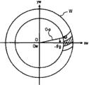
Then, the spherical contact 112 that makes gauge head 110 a bit contacts with the flank of tooth Xw's of workpiece W, reads the center p (px, py, pz) (with reference to Figure 15) of spherical contact 112.According to its result, calculate the length L t (=px2+py2) 1/2) of the straight line O-p in the xy plane of from initial point O to center p (px, py, pz).
Next, in the coordinate system Og of gear (coordinate system of theoretical formula), obtain the position that supposition distance from the gear centre in the xgyg plane to spherical contact 112 center pg when height pz makes spherical contact 112 contact with the theoretical flank of tooth of representing with flank of tooth formula (4) equals Lt, calculate xg axle and center pg angulation θ g.
Then, as shown in figure 16, this rectilinear direction that only makes straight line O-p when the z axle revolution-θ g angle is decided to be xw axle (X-axis of workpiece coordinate system), set by initial point O, with the yw axle (Y-axis of workpiece coordinate system) of xw axle quadrature, simultaneously, the z axle directly as zw axle (the Z axle of workpiece coordinate system).Handle by these, set with theoretical formula in the consistent workpiece coordinate system Ow of gear coordinate system Og.
At this, if carry out same processing, obtain a plurality of workpiece coordinate systems for a plurality of points (the axial height of z also can be inequality) of the flank of tooth, ask its mean value as workpiece coordinate system Ow, can set workpiece coordinate system more accurately.
Like this, measurement coordinate system is turned round set the occasion of the workpiece coordinate system consistent, because theoretical formula (4), (5) are consistent with flank of tooth formula in the workpiece coordinate system, so it is decided to be workpiece face formula Xw, the normal for tooth surface Nw of unit with the gear coordinate system.
In contrast, in the coordinate system and the inconsistent occasion of workpiece coordinate system of theoretical formula, in S230, carry out coordinate transform.This occasion does not make the workpiece coordinate system revolution, and straight line O-p direction directly as the xw axle, is set workpiece coordinate system, makes each coordinate figure, the axis angle of measuring parts program only turn round a θ g around the zg axle.
Perhaps, also can be make theoretical formula (4), (5) around the zg axle only turn round-θ g angle calculates workpiece coordinate formula Xw and the normal for tooth surface Nw of unit, according to this new workpiece coordinate formula, can measure parts program by regeneration.
End process in S120, execution is measured parts program and can be carried out the measurement of workpiece W as required then.
[embodiment 2]
Embodiment 2 is replaced as calculation element 400 with the computing machine 300 of embodiment 1, and other formation is identical with embodiment 2.
Figure 17 represents the block diagram of calculation element 400.
In this Figure 17, the movement content of parameter input circuit 401 is identical with the S20 of Fig. 4, the movement content of theoretical formula counting circuit 402 is identical with the S30 of Fig. 4, the movement content of measurement range initialization circuit 403 is identical with the S40 of Fig. 4, the movement content of representative point counting circuit 404 is identical with the S50 of Fig. 4, the movement content of interior angle angle decision circuit 405 is identical with the S60 of Fig. 4, the movement content of measurement range partitioning circuitry 406 is identical with the S70 of Fig. 4, the movement content of axis angle decision-making circuit 407 is identical with the S80 of Fig. 4, the movement content of condition entry circuit 408 is identical with the S90 of Fig. 4, the movement content of program generative circuit 409 is identical with S100, the movement content of coordinate system initialization circuit 410 is identical with the S110 of Fig. 4, its detailed description of Therefore, omited.
But, in the known occasion of theoretical formula, perhaps from the analysis result of measurement data, deriving the occasion of shape formula, can replace parameter input circuit 401 and theoretical formula counting circuit 402 with theoretical formula input circuit, direct input hypothesis formula or shape formula, replacement is calculated according to the isoparametric theoretical formula of design load, is used as theoretical formula in each circuit afterwards.
In addition, also can constitute coordinate system initialization circuit 410 by coordinate system correction decision circuitry (identical), coordinate system correction circuit (identical), coordinate conversion circuit (identical) with the S230 action with the S220 action with the S210 action.
In addition, in each circuit, comprise the memory circuit of the specified volume of various input data of storage and result of calculation as required.
Have again, this calculation element 400 also has not shown various input-output units (keyboard, mouse, display, printer, circuit input-output unit, auxilary unit etc.), can carry out various operations and computing result's demonstration or printing etc. according to purpose.
Carry out by the not shown measurement parts program executive circuit of calculation element 400 with the measurement parts program that program generative circuit 409 generates, export the measurement data of stipulating through control device 200 control three-dimensional measuring machines 100 and from control device 200.
Which have again, no matter in embodiment, all by the horizontal rotation mechanism of face azimuth axis angle control gauge head, by the vertical bank driving mechanism of tilt axis angle control gauge head.
[variation]
Variation is just different with the processing among the S20~S50 of the measuring method (Fig. 4) of embodiment 1, and other are identical with embodiment 1.
At this, the processing in the variation corresponding with treatment S 20~S50 among the embodiment 1 is decided to be S20 '~S50 '.
In this variation, in basic parameter (for example Figure 21) and the cutting parameter (for example Figure 22) of the middle input of S20 ' according to the design drawing (two-dimensional design figure shown in Figure 180) of workpiece W (gear).At this, the cutting parameter also can be the theoretical value or the inferred value of inferring from the result who measures actual gear.
Then, in S30 ', calculate the theoretical formula of gear teeth face according to basic parameter and cutting parameter. the cutting process according to theoretic cutting parameter or deduction cutting parameter can be recorded and narrated and calculate to mechanics to theoretical formula, for example, obtain the flank of tooth formula Xg and the normal for tooth surface Ng. of unit of the ring gear of hypoid gear by formula (4), (5)
At this, Xg, A (about around the rotating transformation matrix of coordinates of xm axle), Xgc (position vector on the cutter sword face), Dg (position of the center cutter Oc among the coordinate system Om of gear cutting machine), Ngc (unit normal on the cutter sword face) are vectors.U represents that angle of revolution, the v of cutter 1 represent the distance from center cutter Oc to cutter sword face.λ gr represents machine dedendum angle (coning angle at the bottom of the tooth) (with reference to Figure 25).
Next, the coordinate transform coefficient between the theoretical coordinate system (xg, yg, zg) of the initial point Og (xd, zd) of the design coordinate system of calculating two-dimensional design figure and cube theory formula.
The initial point Og of the theoretical coordinate system of the gear among Figure 25 and the distance of back of work Wb are Lg.Relative therewith, in design coordinate system shown in Figure 180,,, but the amount of bias of distance L g is arranged so theoretical coordinate is the zg axle of Og and the position consistency that designs the zd axle of coordinate system Od because initial point Od is positioned on the back of work Wb.
In addition, because being the xg axle of Og and the xd axle of design coordinate system Od, theoretical coordinate is parallel to each other, so is the coordinate transform of (xg, yg, zg) from the design coordinate system Od (xd, zd) of two-dimensional design figure to the theoretical coordinate of cube theory formula, can increase amount of bias one Lg (coordinate transform coefficient) on the zd axial coordinate of design coordinate system Od.By this coordinate transform operation, the point of the appointment on the two-dimensional design coordinate system Od (xd, zd) is corresponding with point on the xgzg plane of the theoretical coordinate system (zg, yg, zg) of cube theory formula.
Then, in the middle setting measurement scope of S40 '.This measurement range is set at the zone of containing representative point (for example Q1) in design coordinate system shown in Figure 180.
Then, at the D coordinates value and the normal vector of the representative point of middle each measurement range of calculating of S50 '.
The setting of representative point can be used algorithm similarly to Example 1.
The appointment of this representative point is by specified measurement point (Q1, Q2......Qn) on the two-dimensional design figure of Figure 18, and input coordinate figure (xd, zd) separately carries out.
Then, calculate D coordinates value and the normal vector of each specified point (Q1, Q2......Qn).
By illustrated like that, by the coordinate transform coefficient each specified point (Q1, Q2......Qn) being transformed to theoretical coordinate is on the xgzg plane on the Og (with reference to Figure 19).
Next, obtain the distance L i from specified point Qi to initial point Og, the distance of search from initial point Og to the Gi that represents with theoretical flank of tooth formula Xg equals the some Gi of this distance L i.
If the some Gi on the theoretical flank of tooth determined,, obtain D coordinates value and normal vector in the theoretical coordinate system of a Gi by flank of tooth formula Xg (formula 4) and the normal for tooth surface Ng of unit (formula 5).
Have again, the generation of the program of this variation, basic identical with the generation (S100) of the measurement parts program of embodiment 1, but in this variation, owing to can obtain the D coordinates value and the normal vector of the specified point (Qn) of appointment according to two-dimensional design figure, so can be according to two-dimensional design figure specified measurement point, because measuring condition (diameter of the spherical contact 112 of gauge head etc.) has been transfused to, so according to they measurement parts programs among the generative theory coordinate system Og easily.
At this, because with contacting signal probe and profiling gauge head the time, because of the different measuring method differences that make of the gauge head that uses, so generate the measurement parts program corresponding (activation signal is measured parts program, and parts program etc. is measured in profiling) with gauge head.
In addition, set (S110) afterwards at coordinate system, at the measurement parts program that carry out to generate and after obtaining measurement data M, also can calculate this measurement data and measurement point theory three-dimensional coordinate figure (equaling the coordinate figure of workpiece coordinate system Ow) error and show this error or export etc.
In addition, in this variation, represented generation, carried out the example of measuring parts program and obtaining measurement data, but as its distortion, can carry out manual measurement yet, this occasion does not need to measure parts program and generates step (S100).
In the occasion of carrying out manual measurement, coordinate system is set (S110) afterwards, with manual mobile gauge head and spherical contact 112 is contacted with the measuring object face of workpiece, by the activation signal S that at this moment produces each count value D (xi, i, Zi) as measurement data input computing machine 300.
Then, according to x axial coordinate value xi and the z axial coordinate value zi of count value D, the same specified point that carries out with the S50 ' of variation calculates, and the some Gi among the search theory coordinate system Og obtains the theory three-dimensional coordinate figure of this Gi.
Then, calculate the error of the theory three-dimensional coordinate figure (equaling the coordinate figure of workpiece coordinate Ow) of measurement data M and measurement point, export this error.
The present invention is not limited to these embodiment.
For example, in embodiment 1,2, represented not make this but do not limit to, in character of surface measuring machines such as surface finish measurement machine, contour shape measuring machine, roundness measurement machine, image measurement machine, also can implement the present invention with the example of three-dimensional measuring machine as measuring machine.
In addition, being not limited to the character of surface measuring machine of measuring with respect to the fixing workpiece moving detector of mounting, also can be the character of surface measuring machine that determinand is moved measure with respect to the detecting device that is fixed.
Have, these can make the program that general-purpose computers are carried out from S10 to S120 with from the processing sequence of S200 to S240 again, and this program can be stored in and supplies with the user in the storage medium.At this, this program can be any language such as the machine language carried out of general-purpose computers, assembly language, higher level lanquage.As the execution form in the computing machine, can be form by the compiler compiling, also can be the intermediate language form of carrying out by translater.As the form that provides to the user, in being stored in various storage mediums such as floppy disk, MO dish, DVD dish, tape, provide and, also can provide via the communication line that contains wired or wireless the Internet.
Claims (17)
1. the measuring method of a curve surface of workpiece is characterized in that, comprising:
Acquisition is by the theoretical formula input step of the theoretical formula of the workpiece of the gauge head measurement curved surface with contact pilotage;
Set measurement range setting step as the measurement range of the scope of on aforementioned curved surface, measuring;
On aforementioned measurement range, set representative point, calculate the representative point calculation procedure of the coordinate figure and the normal vector of this representative point according to aforementioned theoretical formula;
Calculate the tangent line vector of the face direction of the above-mentioned curved surface in the above-mentioned measurement range according to aforementioned normal vector, determine the axis angle deciding step of the face azimuth axis angle of aforementioned contact pilotage according to this tangent line vector by each aforementioned measurement range; And
The axis angle of above-mentioned contact pilotage is changed to the above-mentioned axis angle that determines is carried out the measurement of above-mentioned curved surface in above-mentioned measurement range scope measuring process.
2. the measuring method of curve surface of workpiece as claimed in claim 1 is characterized in that, aforementioned theoretical formula input step comprises:
The parameter input step of the basic parameter of input said workpiece;
Calculate the theoretical formula calculation procedure of the theoretical formula of said workpiece according to aforementioned basic parameter.
3. the measuring method of curve surface of workpiece as claimed in claim 1 is characterized in that,
In aforementioned representative point calculation procedure, aforementioned representative point comprises as the 1st end points of an end of aforementioned measurement range with as the 2nd end points of another end points of aforementioned measurement range, calculate the 1st end points coordinate figure, the 1st end-point method line vector, the 2nd end points coordinate figure and the 2nd end-point method line vector according to aforementioned theoretical formula
In aforementioned axis angle deciding step, the aforementioned tangent line vector according to calculating from aforementioned the 1st end-point method line vector and aforementioned the 2nd end-point method line vector determines aforementioned azimuth axis angle.
4. the measuring method of curve surface of workpiece as claimed in claim 3, it is characterized in that, in aforementioned axis angle deciding step, synthesize aforementioned the 1st normal vector and aforementioned the 2nd normal vector and calculate the method for representatives line vector, and calculate representative tangent line vector as aforementioned tangent line vector according to this method of representatives line vector, represent aforementioned azimuth axis angle of tangent line vector decision according to this.
5. the measuring method of curve surface of workpiece as claimed in claim 3, it is characterized in that, in aforementioned axis angle deciding step, calculate the 1st tangent line vector and the 2nd tangent line vector according to aforementioned the 1st normal vector and aforementioned the 2nd normal vector, calculate aforementioned tangent line vector and determine above-mentioned azimuth axis angle according to the 1st tangent line vector and the 2nd tangent line vector.
6. the measuring method of curve surface of workpiece as claimed in claim 1 is characterized in that, sets in the step in aforementioned measurement range, sets the measurement range of the specified quantity that is predetermined.
7. the measuring method of curve surface of workpiece as claimed in claim 3, it is characterized in that, obtain the interior angle angle of the angle of aforementioned the 1st normal vector and aforementioned the 2nd normal vector, surpass the occasion of predetermined angular in this interior angle angle, also has the measurement range segmentation procedure of cutting apart aforementioned measurement range
Carry out aforementioned measurement range segmentation procedure and aforementioned representative point calculation procedure repeatedly, become up to aforementioned interior angle angle and be less than or equal to aforementioned predetermined angular,
In aforementioned axis angle deciding step, on each aforementioned measurement range of cutting apart, determine aforementioned azimuth axis angle.
8. the measuring method of curve surface of workpiece as claimed in claim 1 is characterized in that, in aforementioned axis angle deciding step, determines the tilt axis angle of aforementioned contact pilotage according to the workpiece shape of aforementioned measurement range.
9. the measuring method of curve surface of workpiece as claimed in claim 1 is characterized in that, also has:
Import the condition entry step of the measuring condition of the information that contains measuring machine;
Generate the program that is used to carry out the measurement parts program that said workpiece measures according to aforementioned theoretical formula and generate step.
10. the measuring method of curve surface of workpiece as claimed in claim 9 is characterized in that, aforementioned measurement parts program contains the aforementioned contact pilotage of handlebar and adjusts to order on the aforementioned axis angle.
11. the measuring method of curve surface of workpiece as claimed in claim 1 is characterized in that, also has the coordinate system setting step of setting workpiece coordinate system according to the posture that is positioned in the said workpiece on the measuring machine.
12. the measuring method of curve surface of workpiece as claimed in claim 11 is characterized in that, aforementioned coordinate system is set step and is also had the consistent coordinate system correction step of theoretical coordinate system that makes said workpiece coordinate system and aforementioned theoretical formula.
13. the measuring method of curve surface of workpiece as claimed in claim 11, it is characterized in that, aforementioned coordinate system is set step, also have when the theoretical coordinate of said workpiece coordinate system and aforementioned theoretical formula is different, angular transformation becomes the coordinate figure represented with the said workpiece coordinate system and the coordinate transform step of axis angle with aforementioned axis the coordinate figure of representing with aforementioned theoretical coordinate system.
14. the measuring method of curve surface of workpiece as claimed in claim 1 is characterized in that,
Aforementioned theoretical formula input step comprises:
Input is based on the parameter input step of the basic parameter of the two-dimensional design figure of said workpiece;
Calculate the theoretical formula calculation procedure of the cube theory formula of said workpiece according to aforementioned basic parameter;
Aforementioned representative point calculation procedure is set aforementioned representative point according to aforementioned two-dimensional design figure with two-dimensional coordinate, calculates the D coordinates value and the normal vector of this representative point according to aforementioned cube theory formula.
15. the measuring method of curve surface of workpiece as claimed in claim 14, it is characterized in that also having the design coordinate transform coefficient calculating step of the coordinate transform coefficient between the theoretical coordinate system of the design coordinate system that calculates aforementioned two-dimensional design figure and aforementioned cube theory formula.
16. the measuring method of curve surface of workpiece as claimed in claim 1 is characterized in that, aforementioned gauge head is the either party in contacting signal probe and the profiling gauge head.
17. the measuring method of curve surface of workpiece as claimed in claim 1 is characterized in that, said workpiece is a cross helical gear.
Applications Claiming Priority (4)
| Application Number | Priority Date | Filing Date | Title |
|---|---|---|---|
| JP358637/2003 | 2003-10-20 | ||
| JP358636/2003 | 2003-10-20 | ||
| JP2003358637A JP4322087B2 (en) | 2003-10-20 | 2003-10-20 | Work surface measurement method, program and medium |
| JP2003358636A JP2005122580A (en) | 2003-10-20 | 2003-10-20 | Method for calculating curved surface of workpiece and its program and medium |
Publications (2)
| Publication Number | Publication Date |
|---|---|
| CN1609552A CN1609552A (en) | 2005-04-27 |
| CN1609552B true CN1609552B (en) | 2010-05-05 |
Family
ID=34395663
Family Applications (1)
| Application Number | Title | Priority Date | Filing Date |
|---|---|---|---|
| CN2004100837652A Expired - Fee Related CN1609552B (en) | 2003-10-20 | 2004-10-19 | Method for measuring curved surface of a workpiece |
Country Status (4)
| Country | Link |
|---|---|
| US (1) | US7251580B2 (en) |
| EP (1) | EP1526356B1 (en) |
| CN (1) | CN1609552B (en) |
| DE (1) | DE602004010599T2 (en) |
Families Citing this family (36)
| Publication number | Priority date | Publication date | Assignee | Title |
|---|---|---|---|---|
| JP4593142B2 (en) * | 2003-09-25 | 2010-12-08 | ハイデルベルガー ドルツクマシーネン アクチエンゲゼルシヤフト | System for manufacturing a workpiece under computer control and method for measuring a manufactured workpiece |
| JP4417121B2 (en) * | 2004-01-19 | 2010-02-17 | 株式会社ミツトヨ | Method for passing the object to be measured and surface texture measuring device |
| JP4634867B2 (en) * | 2005-06-03 | 2011-02-16 | 株式会社ミツトヨ | Image measuring system and method |
| GB0518153D0 (en) * | 2005-09-07 | 2005-10-12 | Rolls Royce Plc | Apparatus for measuring wall thicknesses of objects |
| CN100437445C (en) * | 2005-12-23 | 2008-11-26 | 鸿富锦精密工业(深圳)有限公司 | Three dimension off-line collision test system and method |
| KR100952360B1 (en) * | 2008-10-13 | 2010-04-09 | 류만열 | Surface measuring method |
| JP5301412B2 (en) * | 2009-10-21 | 2013-09-25 | 株式会社ミツトヨ | Measuring force control device |
| KR100994741B1 (en) | 2010-05-04 | 2010-11-16 | 주식회사 덕인 | The method of measuring unknown curve with measurement step optimization based on the surface curvature using 3 dimensional coordinate measuring machine |
| DE102010023728A1 (en) * | 2010-06-14 | 2011-12-15 | Liebherr-Verzahntechnik Gmbh | Method of manufacturing a plurality of identical gears by means of machining |
| WO2012037059A1 (en) * | 2010-09-13 | 2012-03-22 | Hexagon Technology Center Gmbh | Method and apparatus for controlling a surface scanning coordinate measuring machine |
| CN102519408B (en) * | 2011-12-12 | 2013-09-11 | 陕西宝成航空仪表有限责任公司 | Method for measuring a plurality of parts at one time by three-coordinate measuring machine |
| WO2013128183A1 (en) * | 2012-02-27 | 2013-09-06 | Taylor Hobson Limited | Surface measurement apparatus and method |
| CN103292729A (en) * | 2013-05-16 | 2013-09-11 | 厦门大学 | Aspheric normal error detecting device |
| CN103438800B (en) * | 2013-08-29 | 2016-04-06 | 厦门大学 | For the space error calculation method of large-aperture optical element precision detection platform |
| US20150178484A1 (en) | 2013-12-20 | 2015-06-25 | Mitutoyo Corporation | Remote Accessory Management in a Programming Environment for a Progammable Metrology System |
| US9606525B2 (en) | 2013-12-23 | 2017-03-28 | Mitutoyo Corporation | Remote accessory for generating customized and synchronized reference notes for a programmable metrology system |
| DE102014112396B4 (en) * | 2014-08-28 | 2022-01-13 | Carl Zeiss Industrielle Messtechnik Gmbh | Procedure for single-point probing of a workpiece and coordinate measuring machine |
| US10545019B2 (en) * | 2015-04-14 | 2020-01-28 | Hexagon Metrology, Inc. | CMM probe path controller and method |
| US9752860B2 (en) | 2015-07-14 | 2017-09-05 | Caterpillar Inc. | System and method for gear measurement |
| CN105631424B (en) * | 2015-12-31 | 2019-05-10 | 山东省计算中心(国家超级计算济南中心) | Workpiece identification method |
| JP6206527B2 (en) * | 2016-03-16 | 2017-10-04 | 横浜ゴム株式会社 | Device for measuring the inner circumference of a circular member |
| DE102016107255B4 (en) * | 2016-04-19 | 2019-09-05 | Carl Zeiss Industrielle Messtechnik Gmbh | Turntable for a coordinate measuring machine with a locking device, coordinate measuring machine and method of operation |
| JP6464209B2 (en) * | 2017-01-27 | 2019-02-06 | ファナック株式会社 | Numerical controller |
| CN107570983B (en) * | 2017-09-05 | 2019-06-14 | 西北工业大学 | Method and system for automatic assembly of curved surface parts |
| CN107588715B (en) * | 2017-10-30 | 2023-08-22 | 合肥工业大学 | A space position detection device and measurement method based on magnetic effect |
| CN108286937B (en) * | 2018-01-30 | 2020-03-24 | 京东方科技集团股份有限公司 | Contact scanning probe, coordinate measuring device, system and method |
| CN108775883B (en) * | 2018-06-30 | 2020-06-02 | 北京动力机械研究所 | Online detection method for rapid replacement precision of impeller parts |
| CN109408936B (en) * | 2018-10-17 | 2022-12-09 | 湖北三江航天江北机械工程有限公司 | Method for processing and online measuring deep blind cavity of gliding radome |
| JP7257942B2 (en) * | 2019-11-29 | 2023-04-14 | 日立Astemo株式会社 | Surface inspection device, shape correction device, and surface inspection method and shape correction method |
| CN112388257B (en) * | 2020-11-10 | 2022-04-12 | 哈尔滨电气动力装备有限公司 | Shielded motor guide bearing bush supporting block processing technology |
| CN114184156B (en) * | 2021-12-01 | 2024-01-16 | 中国第一汽车股份有限公司 | Surveying and mapping method for hypoid bevel gear of drive axle |
| CN115194260B (en) * | 2022-07-11 | 2025-04-18 | 重庆大学 | On-machine measurement method of face gear pitch error based on CNC worm wheel gear grinding machine |
| WO2024048647A1 (en) * | 2022-08-31 | 2024-03-07 | 株式会社ワコム | Evaluation method and evaluation system for electronic pen |
| CN117537736A (en) * | 2023-10-26 | 2024-02-09 | 中国航发沈阳黎明航空发动机有限责任公司 | High-pressure double-layer blisk leaf profile measuring method |
| CN118999441B (en) * | 2024-03-29 | 2025-10-28 | 西安工业大学 | A method for tracing the value of involute with large base circle radius |
| CN118456116B (en) * | 2024-07-15 | 2024-09-20 | 中国航发贵州黎阳航空动力有限公司 | Online alignment method for dovetail type tongue-groove angle direction of turbine disk |
Citations (2)
| Publication number | Priority date | Publication date | Assignee | Title |
|---|---|---|---|---|
| US4901253A (en) * | 1987-02-23 | 1990-02-13 | Mitutoyo Corporation | Coordinate measuring instrument and method of generating pattern data concerning shape of work to be measured |
| CN1424634A (en) * | 2001-12-12 | 2003-06-18 | 布朗和沙普·特萨有限公司 | Calibrating gauge block for calibrating measuring device and method for calibrating measuring device |
Family Cites Families (8)
| Publication number | Priority date | Publication date | Assignee | Title |
|---|---|---|---|---|
| US4166323A (en) | 1973-09-14 | 1979-09-04 | Maag Gear-Wheel & Machine Co. Ltd. | Gear tester for profile and lead testing |
| CH658126A5 (en) | 1983-03-07 | 1986-10-15 | Maag Zahnraeder & Maschinen Ag | MEASURING DEVICE AND METHOD FOR THE INSPECTION OF GEARS. |
| US5271271A (en) * | 1991-04-03 | 1993-12-21 | Frazier Charles H | Method and apparatus for inspection of gears |
| US5547439A (en) * | 1994-03-22 | 1996-08-20 | Stairmaster Sports/Medical Products, Inc. | Exercise system |
| DE19712029A1 (en) * | 1997-03-21 | 1998-09-24 | Zeiss Carl Fa | Method for controlling coordinate measuring machines according to target data |
| DE19821371A1 (en) | 1998-05-13 | 1999-11-18 | Zeiss Carl Fa | Measuring workpiece with coordinate measuring appliance |
| EP1330686B1 (en) | 2000-09-15 | 2006-12-27 | Werth Messtechnik GmbH | Method for generating a measuring program for a co-ordinate measuring device |
| DE10131160A1 (en) | 2001-06-29 | 2003-01-16 | Zeiss Carl | Method for operating a coordinate measuring machine with a swivel-swivel joint |
-
2004
- 2004-10-14 US US10/965,335 patent/US7251580B2/en not_active Expired - Lifetime
- 2004-10-19 CN CN2004100837652A patent/CN1609552B/en not_active Expired - Fee Related
- 2004-10-19 EP EP04024863A patent/EP1526356B1/en not_active Expired - Lifetime
- 2004-10-19 DE DE602004010599T patent/DE602004010599T2/en not_active Expired - Lifetime
Patent Citations (2)
| Publication number | Priority date | Publication date | Assignee | Title |
|---|---|---|---|---|
| US4901253A (en) * | 1987-02-23 | 1990-02-13 | Mitutoyo Corporation | Coordinate measuring instrument and method of generating pattern data concerning shape of work to be measured |
| CN1424634A (en) * | 2001-12-12 | 2003-06-18 | 布朗和沙普·特萨有限公司 | Calibrating gauge block for calibrating measuring device and method for calibrating measuring device |
Also Published As
| Publication number | Publication date |
|---|---|
| US20050086025A1 (en) | 2005-04-21 |
| US7251580B2 (en) | 2007-07-31 |
| EP1526356B1 (en) | 2007-12-12 |
| EP1526356A2 (en) | 2005-04-27 |
| DE602004010599T2 (en) | 2008-12-04 |
| DE602004010599D1 (en) | 2008-01-24 |
| EP1526356A3 (en) | 2006-02-01 |
| CN1609552A (en) | 2005-04-27 |
Similar Documents
| Publication | Publication Date | Title |
|---|---|---|
| CN1609552B (en) | Method for measuring curved surface of a workpiece | |
| CN103328154B (en) | Error measuring device and error measuring method | |
| US10018459B2 (en) | Method for the location determination of the involutes in gears | |
| Lotze et al. | 3D gear measurement by CMM | |
| CN103302550B (en) | Lens shape machining method and lens shape machining device | |
| Nojedeh et al. | Tool path accuracy enhancement through geometrical error compensation | |
| Pereira et al. | Characterization and compensation of dynamic errors of a scanning coordinate measuring machine | |
| US7715942B2 (en) | Method for controlling a movable tool, input device and machine tool | |
| US9969019B2 (en) | Method for the gear manufacturing machining of a workpiece by a diagonal generating method | |
| Shao et al. | Data-driven operation and compensation approaches to tooth flank form error measurement for spiral bevel and hypoid gears | |
| CN101903836A (en) | Determination of the exercise route | |
| CN102375436B (en) | For generating the method and device of the control data forming flank of tooth portion by milling workpiece on lathe | |
| CN108073132A (en) | For compensating the system and method for multiaxis manufacture system | |
| Krawiec et al. | A proposal of measurement methodology and assessment of manufacturing methods of nontypical cog belt pulleys | |
| US9873160B2 (en) | Method and apparatus for the gear manufacturing machining of a workpiece by a diagonal generating method | |
| JP3752398B2 (en) | Correction method of twist groove forming grinding process and twist groove forming grinding apparatus | |
| EP1442270A1 (en) | Tolerance digitizing method | |
| Zhong et al. | An optimal method for improving volumetric error compensation in machine tools based on squareness error identification | |
| JP3634146B2 (en) | Grinding wheel shaping error correction method, grinding wheel shaping / straight groove forming grinding error correction method, and error correction devices thereof | |
| US7050925B2 (en) | Apparatus for integrated tool manufacture and method therefor | |
| CN101750044A (en) | Method for precisely measuring 3D profile by using measuring needle central coordinate and vector compensation technology | |
| US7421363B2 (en) | Method for virtual inspection of virtually machined parts | |
| JP2005309673A (en) | Nc machine tool and compensation working method | |
| Zargarbashi et al. | A model based method for centering double ball bar test results preventing fictitious ovalization effects | |
| Katz | Cutting mechanics of the gear shaping process |
Legal Events
| Date | Code | Title | Description |
|---|---|---|---|
| C06 | Publication | ||
| PB01 | Publication | ||
| C10 | Entry into substantive examination | ||
| SE01 | Entry into force of request for substantive examination | ||
| C14 | Grant of patent or utility model | ||
| GR01 | Patent grant | ||
| CF01 | Termination of patent right due to non-payment of annual fee |
Granted publication date: 20100505 Termination date: 20201019 |
|
| CF01 | Termination of patent right due to non-payment of annual fee |