CN1601333A - Megneto-optical optical element - Google Patents
Megneto-optical optical element Download PDFInfo
- Publication number
- CN1601333A CN1601333A CN200410087471.7A CN200410087471A CN1601333A CN 1601333 A CN1601333 A CN 1601333A CN 200410087471 A CN200410087471 A CN 200410087471A CN 1601333 A CN1601333 A CN 1601333A
- Authority
- CN
- China
- Prior art keywords
- mentioned
- optical
- magnetic field
- light
- faraday rotator
- Prior art date
- Legal status (The legal status is an assumption and is not a legal conclusion. Google has not performed a legal analysis and makes no representation as to the accuracy of the status listed.)
- Pending
Links
Images


Classifications
-
- G—PHYSICS
- G02—OPTICS
- G02F—OPTICAL DEVICES OR ARRANGEMENTS FOR THE CONTROL OF LIGHT BY MODIFICATION OF THE OPTICAL PROPERTIES OF THE MEDIA OF THE ELEMENTS INVOLVED THEREIN; NON-LINEAR OPTICS; FREQUENCY-CHANGING OF LIGHT; OPTICAL LOGIC ELEMENTS; OPTICAL ANALOGUE/DIGITAL CONVERTERS
- G02F1/00—Devices or arrangements for the control of the intensity, colour, phase, polarisation or direction of light arriving from an independent light source, e.g. switching, gating or modulating; Non-linear optics
- G02F1/01—Devices or arrangements for the control of the intensity, colour, phase, polarisation or direction of light arriving from an independent light source, e.g. switching, gating or modulating; Non-linear optics for the control of the intensity, phase, polarisation or colour
- G02F1/09—Devices or arrangements for the control of the intensity, colour, phase, polarisation or direction of light arriving from an independent light source, e.g. switching, gating or modulating; Non-linear optics for the control of the intensity, phase, polarisation or colour based on magneto-optical elements, e.g. exhibiting Faraday effect
- G02F1/092—Operation of the cell; Circuit arrangements
-
- G—PHYSICS
- G02—OPTICS
- G02F—OPTICAL DEVICES OR ARRANGEMENTS FOR THE CONTROL OF LIGHT BY MODIFICATION OF THE OPTICAL PROPERTIES OF THE MEDIA OF THE ELEMENTS INVOLVED THEREIN; NON-LINEAR OPTICS; FREQUENCY-CHANGING OF LIGHT; OPTICAL LOGIC ELEMENTS; OPTICAL ANALOGUE/DIGITAL CONVERTERS
- G02F2201/00—Constructional arrangements not provided for in groups G02F1/00 - G02F7/00
- G02F2201/17—Multi-pass arrangements, i.e. arrangements to pass light a plurality of times through the same element, e.g. by using an enhancement cavity
-
- G—PHYSICS
- G02—OPTICS
- G02F—OPTICAL DEVICES OR ARRANGEMENTS FOR THE CONTROL OF LIGHT BY MODIFICATION OF THE OPTICAL PROPERTIES OF THE MEDIA OF THE ELEMENTS INVOLVED THEREIN; NON-LINEAR OPTICS; FREQUENCY-CHANGING OF LIGHT; OPTICAL LOGIC ELEMENTS; OPTICAL ANALOGUE/DIGITAL CONVERTERS
- G02F2201/00—Constructional arrangements not provided for in groups G02F1/00 - G02F7/00
- G02F2201/34—Constructional arrangements not provided for in groups G02F1/00 - G02F7/00 reflector
Abstract
The invention provides small-sized, power-saving and easily-producible magneto-optical devices. The magneto-optical device comprises a Faraday rotator having nearly parallel surfaces and a Z-direction magnetic easy axis; a total reflection film formed partly on one surface of the Faraday rotator; another total reflection film formed partly on the other surface thereof; a light input region through which light enters the Faraday rotator; a light output region through which the light having alternately reflected on the total reflection films goes out of the Faraday rotator; a permanent magnet that forms a predetermined magnetic domain structure in the Faraday rotator and applies a magnetic field component in the Z-direction to the Faraday rotator so that the magnetization direction could be the same both in the light input region and the light output region; and an electromagnet that varies the position at which the magnetic field component applied to the Faraday rotator is 0 (zero).
Description
Technical field
The present invention relates to Megneto-optical optical element, particularly relate to polarized light controller or photomodulator, magneto-optic opticses such as variable optical attenuator, optoisolator, light circulator.
Background technology
In the high-speed light communication of transfer rate 40Gbps, polarization mode dispersion becomes one of main transmission deterioration essential factor.The research of the polarization mode dispersion of the influence of compensating polarization mode dispersion in recent years (PMD) compensator is carried out actively for this reason.As one of main composition device of PMD compensator, the polarized light controller of control light polarization state is arranged.As disclosed in the non-patent literature 1, as the optical device that constitutes the polarized light controller, lithium niobate (LN) or liquid crystal etc., optical fiber ス Network イ one ザ, variable Faraday rotator etc. are known.Particularly because of polarized light controller with variable Faraday rotator, its response time is quite short, reach hundreds of μ sec, structure also is made of garnet crystal, thus insert loss, polarized light dependent loss optical characteristics such as (PDL) and reliability also can obtain with in the past by the characteristic of movable mold member (module) same degree.Therefore, as use variable Faraday rotator, then compare, can constitute the polarized light controller (with reference to non-patent literature 1) that obtains equilibrium with other device.Variable Faraday rotator comprises magneto-optical crystal, and the electromagnet that applies magnetic field on magneto-optical crystal.By make the current change that flows through in electromagnet, control is applied to the magnetic field intensity on the magneto-optical crystal, just can control faraday's rotation angle by the magnetization change that makes magneto-optical crystal.
In the patent documentation 1 method that is applied to the magnetic field on the magneto-optical crystal of controlling is being disclosed for example.Now describe with regard to this magnetic field control method with Figure 25.Figure 25 (a) represents variable optical attenuator, and this variable optical attenuator comprises Faraday rotator (magneto-optical crystal) 113 and polarizer 112.In addition, this variable optical attenuator has permanent magnet 114 and the electromagnet 115 that applies magnetic field in the direction with relative Faraday rotator 113 mutually orthogonals, and the variable current source 116 of electromagnet 115 being supplied with drive current.
The transmission direction that is applied to the light beam 117 in magnetic direction and the Faraday rotator 113 on the Faraday rotator 113 by permanent magnet 114 is parallel, and being applied to magnetic direction and the magnetic field that is produced by the permanent magnet in the Faraday rotator 113 114 on the Faraday rotator 113 by electromagnet 115, to apply direction vertical with the transmission direction of light beam 117.
In Figure 25 (b), arrow the 102, the 105th, the direction of magnetization in the expression Faraday rotator 113 and the vector of size thereof, arrow the 101, the 103rd, the vector that applies magnetic direction and size that expression applies from the outside, arrow 104 are expression vectors by the direction and the size of the resultant magnetic field in two magnetic fields of arrow 101,103 expressions.The Z direction is the direction of propagation of light in the Faraday rotator 113 among the figure, directions X and Z direction quadrature.Faraday rotator 113 is become the state of saturated magnetization 102 by the magnetic field 101 of the Z direction of external permanent magnet 114 generations.Then when applying the magnetic field 103 of directions X by electromagnet 115, the external magnetic field becomes resultant magnetic field 104, and Faraday rotator 113 becomes the state of magnetization 105.The size of this magnetization 105 is big or small identical with saturated magnetization 102, so Faraday rotator 113 is in the saturated magnetization state.
Like this, on Faraday rotator 113, apply the magnetic field 101 of Z direction in advance, make Faraday rotator 113 become the saturated magnetization state, on Faraday rotator 113, apply the magnetic field 103 of directions X again by electromagnet 115 by permanent magnet 114.Resultant magnetic field 104 by two magnetic fields 101,103 makes the direction of magnetization of Faraday rotator 113 from magnetizing 102 to 105 anglec of rotation θ of magnetization, the size of the magnetization component 106 of control Z direction then.Faraday's rotation angle changes according to the size of this magnetization component 106, and in the occasion of this method, the saturated magnetization district uses because Faraday rotator 113 is everlasting, the feature that repeatability makes faraday's rotation angle change well so have the hysteresis of not producing.
Yet, in patent documentation 1 in the magnetic field applying method of record, in order under the state that applies magnetic field 101 by permanent magnet 114, magnetization as one man to be rotated, and must strengthen the magnetic field 103 that applies by electromagnet 115.Electromagnet 115 is maximized, perhaps make and flow through big electric current in the electromagnet 115, cause to be difficult to make Megneto-optical optical element miniaturization, the low problem of power consumption.
In addition, Faraday rotator 113 adopts the magnetic garnet monocrystal film that grows up to by liquid phase epitaxy (LPE) method to make.Because when making light when the direction along the film aufwuchsplate of magnetic garnet monocrystal film sees through, characteristics such as extinction ratio descend, so light is seen through in the direction perpendicular to the film aufwuchsplate.At this moment, with the thickness maximum of the film aufwuchsplate vertical direction of Faraday rotator 113 be about 400 μ m, faraday's rotation angle of acquisition is about 45 °.Therefore for the polarized light controller of the above polarized light rotation angle variable amplitude of needs 180 degree, essential with a plurality of (common 6~8) Faraday rotator 113.Thereby the miniaturization, the cost degradation that make Megneto-optical optical element become difficulty more.
Patent documentation 1: specially permit communique No. 2815509
Patent documentation 2: No. 5657151 instructions of United States Patent (USP)
Patent documentation 3: the spy opens flat 7-199137 communique
Patent documentation 4: No. 4239337 instructions of United States Patent (USP)
Patent documentation 5: No. 3420601 instructions of United States Patent (USP)
Non-patent literature 1: 5 people are waited with expanding in the Ikeda, and " type that infinitely knocks into the back partial wave system is driven the device exploitation ", the Furukawa Times is put down in January, 15, and No. 111, the 31-36 page or leaf.
Summary of the invention
The Megneto-optical optical element that the purpose of this invention is to provide small-sized, low power consumption electric power and low price.
Above-mentioned purpose is by being that the Megneto-optical optical element of feature reaches with following, and it comprises: have the opposed the 1st and the magneto-optical crystal on the 2nd surface; Be configured in the 1st total reflection portion at least a portion of above-mentioned the 1st face side of above-mentioned magneto-optical crystal; Be configured in the 2nd total reflection portion at least a portion of above-mentioned the 2nd face side of above-mentioned magneto-optical crystal; Light is to the incident light district of above-mentioned magneto-optical crystal incident; Above-mentioned light by the above-mentioned the 1st and the 2nd total reflection portion alternating reflex penetrates the district from the light that above-mentioned magneto-optical crystal penetrates; Penetrate the mode that does not have domain wall in the district applies the magnetic field domain wall to above-mentioned magneto-optical crystal magnetic field applying mechanism by above-mentioned incident light district and above-mentioned light.
Megneto-optical optical element as the invention described above is characterized in that: above-mentioned magnetic field applying mechanism applies magnetic field to above-mentioned magneto-optical crystal, makes at above-mentioned incident light district consistent with the direction of magnetization that above-mentioned light penetrates in distinguishing.
Megneto-optical optical element as the invention described above is characterized in that: above-mentioned incident light district is configured on above-mentioned the 1st surface, and above-mentioned light penetrates the district and is configured on above-mentioned the 2nd surface.
Megneto-optical optical element as the invention described above is characterized in that: above-mentioned incident light district and above-mentioned light penetrate the district and are configured in simultaneously on above-mentioned the 1st surface.
Megneto-optical optical element as the invention described above, it is characterized in that: above-mentioned magneto-optical crystal has given easy magnetizing axis, comprises magnetic region A that the folk prescription by being parallel to above-mentioned easy magnetizing axis constitutes to magnetization and the magnetic region B by constituting with the rightabout magnetization of the direction of magnetization of above-mentioned magnetic region A.
Megneto-optical optical element as the invention described above, it is characterized in that: above-mentioned magnetic field applying mechanism comprise the magnetic field composition that makes the afore mentioned rules direction that is applied on the above-mentioned magneto-optical crystal be the electromagnet of 0 position changeable and respectively be formed on above-mentioned magneto-optical crystal on a plurality of magnetic regions corresponding, each disposes 1 permanent magnet at least.
Megneto-optical optical element as the invention described above, it is characterized in that: above-mentioned magnetic field applying mechanism is included at least one permanent magnet that applies fixed magnetic field on the above-mentioned magneto-optical crystal and applies electromagnet with the variable magnetic field of said fixing magnetic direction different directions on above-mentioned magneto-optical crystal, make the Strength Changes of above-mentioned variable magnetic field, and the resultant magnetic field that makes above-mentioned variable magnetic field and said fixing magnetic field has the above intensity of saturation magnetic field of above-mentioned magneto-optical crystal, and the direction of magnetization of above-mentioned magneto-optical crystal is changed.
In addition, above-mentioned purpose reaches by the Megneto-optical optical element that has with following characteristics, and it comprises: have the opposed the 1st and the magneto-optical crystal on the 2nd surface; Be configured in the 1st total reflection portion at least a portion of above-mentioned the 1st face side of above-mentioned magneto-optical crystal; Be configured in the 2nd total reflection portion at least a portion of above-mentioned the 2nd face side of above-mentioned magneto-optical crystal; Light is to the incident light district of above-mentioned magneto-optical crystal incident; Above-mentioned light by the above-mentioned the 1st and the 2nd total reflection portion surface alternating reflex penetrates the district from the light that above-mentioned magneto-optical crystal penetrates; The magnetic field applying mechanism, this magnetic field applying mechanism is included in electromagnet that applies variable magnetic field on the above-mentioned magneto-optical crystal and at least one permanent magnet that applies fixed magnetic field on above-mentioned magneto-optical crystal, and wherein this electromagnet comprises near an end of the back side of above-mentioned the 1st total reflection portion configuration with near the yoke of the other end of the back side configuration of above-mentioned the 2nd total reflection portion be wound on coil on the above-mentioned yoke.
Megneto-optical optical element as the invention described above, it is characterized in that: above-mentioned magneto-optical crystal has given easy magnetizing axis, comprises magnetic region A that the folk prescription by being parallel to above-mentioned easy magnetizing axis constitutes to magnetization and the magnetic region B by constituting with the rightabout magnetization of the direction of magnetization of above-mentioned magnetic region A.
Megneto-optical optical element as the invention described above, it is characterized in that: the direction of above-mentioned variable magnetic field is different mutually with the direction in said fixing magnetic field, above-mentioned magnetic field applying mechanism makes the Strength Changes of above-mentioned variable magnetic field, so that the resultant magnetic field in above-mentioned variable magnetic field and said fixing magnetic field has the above intensity of saturation magnetic field of above-mentioned magneto-optical crystal, and the direction of magnetization of above-mentioned magneto-optical crystal is changed.
Advantage of the present invention is to realize small-sized, low power consumption and the low Megneto-optical optical element of price.
Description of drawings
Fig. 1 is the figure of the Megneto-optical optical element structure of expression the 1st embodiment of the present invention.
Fig. 2 is the figure that the Megneto-optical optical element of expression the 1st embodiment of the present invention is wanted portion's structure.
Fig. 3 is the figure that is illustrated in issuable problem points in the Megneto-optical optical element of the 1st embodiment of the present invention.
Fig. 4 is the polarized light corner of Megneto-optical optical element of expression the 1st embodiment of the present invention and the dependent curve map of magnetomotive force of loss.
Fig. 5 is the figure of the Megneto-optical optical element structure of expression the 2nd embodiment of the present invention.
Fig. 6 is the figure that wants portion's structure of the Megneto-optical optical element of expression the 2nd embodiment of the present invention.
Fig. 7 is the figure of the configuration of expression permanent magnet and yoke.
Fig. 8 is the curve map that is illustrated near the magnetic-field component intensity the permanent magnet of the configuration shown in Fig. 7.
Fig. 9 is the figure that wants portion's structure of Megneto-optical optical element of the embodiment 2-1 of expression the 2nd embodiment of the present invention.
Figure 10 is the polarized light rotation angle of Megneto-optical optical element of embodiment 2-1 of expression the present invention the 2nd embodiment and the dependent curve map of magnetomotive force of loss.
Figure 11 is the figure that wants portion's structure of Megneto-optical optical element of the embodiment 2-2 of expression the present invention the 2nd embodiment.
Figure 12 is the polarized light rotation angle of Megneto-optical optical element of embodiment 2-2 of expression the present invention the 2nd embodiment and the dependent curve map of magnetomotive force of loss.
Figure 13 is the dependent figure of magnetic region structure of the insertion loss of explanation Megneto-optical optical element.
Figure 14 is the dependent curve map of magnetic region structure of the insertion loss of expression Megneto-optical optical element.
Figure 15 is the dependent curve map of magnetic region structure of the insertion loss of explanation Megneto-optical optical element.
Figure 16 is the dependent curve map of magnetic region structure of the insertion loss of expression Megneto-optical optical element.
Figure 17 is the dependent figure of magnetic region structure of the insertion loss of explanation Megneto-optical optical element.
Figure 18 is the dependent curve map of magnetic region structure of the insertion loss of expression Megneto-optical optical element.
Figure 19 is the figure of the Megneto-optical optical element structure of expression the present invention the 3rd embodiment.
Figure 20 is the figure that the Megneto-optical optical element of expression the present invention the 3rd embodiment is wanted portion's structure.
Figure 21 is the figure that the Megneto-optical optical element of expression the 4th embodiment of the present invention is wanted portion's structure.
Figure 22 is the figure of variation of the Megneto-optical optical element structure of expression the present invention the 4th embodiment.
Figure 23 is the figure of the Megneto-optical optical element structure of expression the present invention the 5th embodiment.
Figure 24 is the figure that the Megneto-optical optical element of expression the present invention the 6th embodiment is wanted portion's structure.
Figure 25 is the schematic configuration of Megneto-optical optical element of explanation prior art and the figure of principle of operation.
Symbol description
1 Megneto-optical optical element
2,2 ', 2 ", 3,4,4 ', 6 polarized light controllers
5 optoisolators
20,20a, 20b, 21,24 Faraday rotators
22,22a, 22b, 23,23a, 23b surface
30,30a, 30b, 31,31a, 31b total reflection film
32,32a, 32b, 33,33a, 33b, 36 non reflecting films
34,34a, 34b, 39 incident light districts
35,35a, 35b, 38 light penetrate the district
40 electromagnet
42,70,71,72 yokes
42a, 42b, 42e, 42f end
42c, 42d, 42g, 42h, 70d, 71d top end face
44 coils
46,47,48,49,66a, 66b, 67a, 67b, 68a, 68b, 69a, 69b, 84,85,86,87,88,90a, 90b, 90c, 90d, 90e, 90f, 90g permanent magnet
46a, 46b, 46c, 47a, 47b, 47c surface
50 input single-mode fibers
52 output single-mode fibers
54,56 lens
58, the optical fiber of 59 band lens
60 1/4 wavelength sheets
62 reflector plates
80,81,82 polarizers
Embodiment
The 1st embodiment
The Megneto-optical optical element of the present invention's the 1st embodiment is described with Fig. 1 and Fig. 2 now.Fig. 1 represents the structure of the Megneto-optical optical element 1 of present embodiment, and what Fig. 2 represented Megneto-optical optical element 1 wants portion's structure.At this, in Fig. 1 and Fig. 2, the working direction of the light beam that throws is made as X-axis in this face in the face parallel with the light entrance face of the magneto-optical crystal of Megneto-optical optical element 1, direction vertical with X-axis in this face is made as Y-axis.And the Z axle is elected as and light incident and the vertical direction of outgoing plane.Fig. 1 represents the structure of the Megneto-optical optical element 1 that edge-Y direction is seen, the structure of portion of the Megneto-optical optical element 1 that Fig. 2 (a) expression edge+Y direction is seen, the structure of portion of the Megneto-optical optical element 1 that Fig. 2 (b) expression edge-Z direction is seen.
Like that, Megneto-optical optical element 1 has the Faraday rotator 20 as magneto-optical crystal shown in Fig. 1 and Fig. 2 (a) and (b).Faraday rotator 20 has along the perpendicular magnetization that manifests easy magnetizing axis perpendicular to the direction (Z direction) of film aufwuchsplate for example with the magnetic garnet single crystals film production that forms by the LPE method.Faraday rotator 20 has the roughly shape of rectangular parallelepiped, and has and be parallel to XY face and opposite one another surface 22,23 simultaneously.Forming non reflecting film 32 (not shown in Fig. 1 and Fig. 2 (b)) near the incident light district 34 of light beam incident, on the other parts on surface 22, form total reflection film (total reflection portion) 30 (not shown in Fig. 2 (b)) in one of them surface 22.In addition, the light of outgoing beam forms non reflecting film 33 (not shown in Fig. 1 and Fig. 2 (b)) near penetrating district 35 in another surface 23, forms total reflection film 31 (not shown in Fig. 2 (b)) on the other parts on surface 23.Incident light district 34 is positioned at Faraday rotator 20-X side, light penetrate district 35 be positioned at Faraday rotator 20+the X side.Form total reflection film 30,31 by metallic films such as evaporation dielectric multilayer film or aluminium on each surface 22,23 of Faraday rotator 20.As looking along the Z direction, near incident light district 34 zone only forms the total reflection film 31 in the total reflection film 30,31, near light penetrates district 35 zone only forms total reflection film 30, penetrates the zone stack between the district 35 and forms total reflection film 30,31 at incident light district 34 and light.Light beam incides in the Faraday rotator 20 from incident light district 34, is alternately repeatedly reflected (multipath reflection) by total reflection film 31,30 surfaces and just penetrates from light ejaculation district 35.On each surface 22,23 of Faraday rotator 20, might not leave no choice but directly form respectively total reflection film 30,31 in addition, and also the substrate (for example glass substrate) that is formed with total reflection film 30 can be configured in surface 22 sides of Faraday rotator 20, the substrate that will be formed with total reflection film 31 is configured in surface 23 sides of Faraday rotator 20.These two substrates for example are configured in respectively on each surface 22,23 of Faraday rotator 20 with the way of contact substantially.In addition, also can be with replacement total reflection films 30,31 such as medal polish faces as total reflection portion.
Megneto-optical optical element 1 has yoke (electromagnetic yoke) 42 (both ends 42a, the 42b of yoke 42 only are shown) that for example comprises " C " word shape and the electromagnet (magnetic field applying mechanism) that is wound on the coil on the yoke 42 in Fig. 1.An end 42a of yoke 42 is near the back side configuration of total reflection film 30, so that its top end face 42c is relative with the back side of total reflection film 30.The other end 42b of yoke 42 is near the back side configuration of total reflection film 31, so that its top end face 42d is relative with the back side of total reflection film 31.The top end face 42c of end 42a and the top end face 42d of end 42b dispose with the cardinal principle central portion of clamping Faraday rotator 20, mode relative to each other.
For example permanent magnet such as ferrite lattice, rare earth element magnet (magnetic field applying mechanism) 46 with along 42 1 end 42a of yoke+mode of directions X adjacency disposes.The flow direction of permanent magnet 46 inside is-the Z direction (direction of magnetization that is permanent magnet 46 is-the Z direction) as arrow among the figure is represented.Permanent magnet 46-top ends of Z side contacts for example back side of total reflection film 30.In addition, permanent magnet 47 with along yoke 42 the other end 42b-mode of directions X adjacency disposes.The flow direction of permanent magnet 47 inside is+Z direction (direction of magnetization that is permanent magnet 47 is+the Z direction).Permanent magnet 47+top ends of Z side contacts for example back side of total reflection film 31.
Faraday rotator 20-zone of X side on, be applied to the above intensity of saturation magnetic field (making the necessary magnetic field of magnetic saturation of Faraday rotator 20) by the magnetic-field component of permanent magnet 47 general+Z directions.Therefore this district becomes to passing through as arrow among the figure is represented+the magnetic region A of the magnetization formation of Z direction.Faraday rotator 20+zone of X side in, be applied to intensity more than the saturation magnetic field by the magnetic-field component of permanent magnet 46 general-Z directions.Therefore this district becomes the magnetic region B that constitutes for the magnetization by-Z direction.Between the zone of the zone of magnetic region A and magnetic region B, form domain wall I as frontier district (boundary surface).At domain wall I, the Z durection component that applies magnetic field almost becomes 0.At this, incident light district 34 is positioned at the a-quadrant, magnetic region, and light penetrates district 35 and is positioned at B zone, magnetic region.Be+θ fs (saturated faraday's rotation angle) if establish faraday's rotation angle of per unit light path of the a-quadrant, magnetic region of Faraday rotator 20, then faraday's rotation angle of the per unit light path in magnetic region B zone is-θ fs.
When in magnet spool, flowing through electric current, for example+magnetic field of Z direction is applied in by near the Faraday rotator 20 the zone of the both ends 42a of yoke 42,42b clamping.Therefore domain wall I moves to+directions X.That is, the a-quadrant, magnetic region broadens with the intensity that applies magnetic field, and B zone in magnetic region narrows down according to its degree.In addition, when flowing through inverse current in magnet coil, the magnetic field of-Z direction just is applied to by near the Faraday rotator 20 the zone of the both ends 42a of yoke 42,42b clamping.Therefore domain wall I moves to-directions X.That is, the zone of magnetic region A narrows down along with the intensity that applies magnetic field, and the zone of magnetic region B broadens according to this degree.In the formation of this example because make yoke 42 both ends 42a, 42b each top end face 42c, 42d relatively near and dispose, so can on Faraday rotator 20, apply magnetic field effectively, and just can apply the magnetic field of desired intensity with little electric current.Domain wall I moves in the zone than light ejaculation district 35 more close-X sides than incident light district 34 more close+X sides, does not have domain wall I in incident light district 34 and light ejaculation district 35.
On one side repeatedly the difference of the light path in the magnetic region B of light path in the polarized light rotation angle that produces during transmission Faraday rotator 20 on one side of reflection and the magnetic region A that is made of the magnetization by+Z direction and the magnetization formation by-Z direction is proportional by the light shown in the light L in Fig. 2.Therefore by applying variable magnetic field and domain wall I edge ± directions X moved in ± Z direction with electromagnet, can make the poor variation of the interior light path of light path in the A of magnetic region and magnetic region B, make the polarized light rotation angle variable.Therefore can make the plane of polarization that is incident on the light beam in the Faraday rotator 20 only rotate desirable angle penetrates.
In the present embodiment, with Faraday rotator 20 with perpendicular magnetization.Usually has perpendicular magnetization with the magnetic garnet monocrystal film of LPE method growth because of growing response magnetic anisotropy performance easy magnetizing axis on perpendicular to the direction of film aufwuchsplate.Therefore the direction of magnetization of magnetic garnet monocrystal film becomes and is the direction perpendicular to the film aufwuchsplate.For as described in the magnetic field applying method of being put down in writing in the patent documentation 1, make the direction of magnetization rotation of Faraday rotator, and must the growing response magnetic anisotropy be lowered in the long heat treatment of carrying out again behind the magnetic garnet monocrystal film of having grown under the high temperature about 1000 ℃.Therefore the manufacturing process that causes Faraday rotator increases such problem.If for example make the interior direction of magnetization of easy magnetizing axis and magnetic region A, B consistent in the present embodiment, then because there is no need to carry out the long heat treatment under the high temperature when making Faraday rotator 20, so can reduce the manufacturing process of Faraday rotator 20, and can realize Megneto-optical optical element easy to manufacture, low price.
In addition, in the present embodiment, be not in the patent documentation 1 the consistent magnetization rotation mode that rotates of such, as to make magneto-optical crystal magnetization of putting down in writing, and domain wall I is moved, make the domain wall move mode of the magnetic region structural change in the Faraday rotator 20.Therefore just can obtain desirable polarized light rotation angle with small-sized electromagnet.Therefore according to present embodiment, can realize Megneto-optical optical element small-sized and that power consumption is low.In addition because response speed is subjected to L (inductance) restriction of electromagnet usually, so, just can realize reducing L, improving response speed if can make the electromagnet miniaturization.
Also have, in the present embodiment, both ends 42a, the 42b of yoke disposes relative to each other along film thickness direction clamping Faraday rotator 20.Therefore can make yoke both ends 42a, 42b configuration near each other, can on Faraday rotator 20, apply variable magnetic field effectively.Therefore can make the further miniaturization of Megneto-optical optical element, reduce power consumption.
In addition, in the present embodiment, Faraday rotator 20 becomes the state of two magnetic regions structures usually, can abortion gives birth to lag behind and repeatability makes the polarized light rotation angle change well.
The 2nd embodiment
The Megneto-optical optical element of the present invention's the 2nd embodiment is described below with reference to Fig. 3 to Figure 18.At first describe with regard to issuable problem points in the Megneto-optical optical element 1 of above-mentioned the 1st embodiment.
Fig. 3 is corresponding with Fig. 2, is illustrated in the light path of the Faraday rotator 20 interior transmission light of Megneto-optical optical element 1.Different with Fig. 2 in Fig. 3, consider the wave beam footpath of light, illustrate as the light path L2 (solid line) on the central shaft of the light beam of almost parallel light, from the light path L1 (long dotted line) of light path L2, from the light path L3 (short dotted line) of light path L2 to+directions X skew to-directions X skew.As shown in Figure 3, in the Megneto-optical optical element 1 of the 1st embodiment, each is all different respectively with regard to each light path L1, L2, L3 for the interior light path of the light path in the A of magnetic region and magnetic region B.Light path in the light path L1 medium magnetic area A is longer than light path L2, and the light path in the B of magnetic region is shorter than light path L2.Light path in the light path L3 in addition, magnetic region A is shorter than light path L2, and B interior light path in magnetic region is longer than light path L2.Like this, the light path in light path in the A of magnetic region and magnetic region B with regard to each light path each not simultaneously, the polarized light rotation angle is just different with light path.Therefore when using the light incident side of optical fiber, output produces diffraction loss at light by Faraday rotator 20 post-concentrations.
Fig. 4 is the polarized light rotation angle of Megneto-optical optical element 1 of expression the 1st embodiment and the dependent curve map of magnetomotive force of loss.Transverse axis is represented the magnetomotive force NI product of the electric current I of crossing at this coil midstream (number of turn N of coil with), and (AT), the longitudinal axis is represented polarized light rotation angle (degree) and loss (dB).Line a1 represents the magnetomotive force dependence of polarized light rotation angle, and line b1 represents the magnetomotive force dependence of loss.At this, the polarized light rotation angle is a relative value, and the polarized light rotation angle when establishing magnetomotive force NI and being 0AT is 0 degree.As shown in Figure 4, though in the variable amplitude that has obtained the polarized light rotation angle more than 400 degree on the Megneto-optical optical element 1, the mean value of loss (diffraction loss) is about 1.8dB than higher, and the amplitude of fluctuation of loss is bigger, about 3.0dB.Therefore, though the Megneto-optical optical element 1 of the 1st embodiment goes on photomodulator that transmission light quantity is modulated etc., have and to be applicable to the such problems such as polarized light controller that loss is low and the loss variation amplitude is little that require.
Fig. 5 represents the structure as the polarized light controller 2 of the Megneto-optical optical element of the present embodiment that addresses the above problem.And Fig. 6 represent polarized light controller 2 want portion's structure.The employing coordinate system identical in Fig. 5 and Fig. 6 with Fig. 1 and Fig. 2.The structure of wanting portion of the polarized light controller 2 that Fig. 6 (a) expression edge+Y direction is seen, the structure of portion of the polarized light controller 2 that Fig. 6 (b) expression edge-Z direction is seen.Shown in Fig. 5 and Fig. 6 (a) and (b), polarized light controller 2 has the Faraday rotator 20 as magneto-optical crystal.Faraday rotator 20 usefulness are made by the magnetic garnet monocrystal film that the LPE method forms, and it has along the perpendicular magnetization that shows easy magnetizing axis perpendicular to the direction (Z direction) of film aufwuchsplate.Faraday rotator 20 has the roughly shape of rectangular parallelepiped, has the surface 22,23 that is parallel to the XY face jointly.Form non reflecting film 32 (not shown in Fig. 6 (b)) near the incident light district 34 of light beam incident in one of them surface 22, on the other parts on surface 22, forming total reflection film 30 (not shown in Fig. 6 (b)).In another surface 23, the light that light beam penetrates forms non reflecting film 33 near penetrating district 35 in addition, and the other parts on surface 23 form total reflection film 31.
As shown in Figure 5, converted directional light as the light of diverging light ejaculation by lens 54 with single-mode fiber 50 from input after, incide the incident light district 34 of Faraday rotator 20.Incide light in the Faraday rotator 20 on one side by total reflection film 31,30 surperficial alternating reflexs,, penetrate district 35 from light and penetrate the back and converged at output with single-mode fiber 52 by lens 56 on one side by in the Faraday rotator 20.Fig. 6 (a) and (b) represent as the light path L2 on the central shaft of the light beam of directional light, from light path L2 to the light path L1 of-directions X skew with from the light path L3 of light path L2 to+directions X skew.
In addition, polarized light controller 2 has yoke 42 that comprises " C " word shape and the electromagnet 40 that is wound on the coil 44 on the yoke 42.An end 42a of yoke 42 is by its top mode relative with the back side of total reflection film 30 disposed near the back side of total reflection film 30.In the part (right side in Fig. 5) on the top of end 42a, imbed permanent magnet 46.The top end face 42c of end 42a and the surperficial 46a of permanent magnet 46 are configured in the roughly same plane.The direction of magnetization of permanent magnet 46 is+the Z direction.The end 42a that is approximately perpendicular to the surperficial 46a of direction of magnetization of permanent magnet 46 and yoke 42 configuration over the ground of not practising physiognomy.At the other end of yoke 42 42b by its top mode relative with the back side of total reflection film 31 disposed near the back side of total reflection film 31.In the part (left side in Fig. 5) on the top of end 42b, imbed permanent magnet 47.The top end face 42d of end 42b and the surperficial 47a of permanent magnet 47 are configured in the same plane substantially.The direction of magnetization of permanent magnet 47 is+the Z direction.Substantially perpendicular to the end 42b of the surperficial 47a of the direction of magnetization of permanent magnet 47 and yoke 42 configuration over the ground of not practising physiognomy.Permanent magnet 46,47 also can be distinguished end 42a, the 42b that directly contacts yoke 42, also can dispose near end 42a, 42b respectively by adhesive phase etc.The top end face 42d clamping Faraday rotator 20 of the top end face 42c of end 42a and end 42b and face one another face ground configuration.
At this, the magnetic field that is produced by permanent magnet 46,47 is described with Fig. 7 and Fig. 8.Fig. 7 represents with being configured in corresponding to the locational yoke 70 of the end 42a of yoke 42 and being configured in the structure that replaces yokes 42 corresponding to the position upper magnet yoke 71 of the end 42b of yoke 42.Two surperficial 46b, 46c contacts of permanent magnet 46 are on yoke 70.The top end face 70d of yoke 70 and the surperficial 46a of permanent magnet 46 dispose at grade substantially.This contact of surperficial 47b, the 47c of permanent magnet 47 is on yoke 71.The top end face 71d of yoke 71 and the surperficial 47a of permanent magnet 47 are configured on the roughly same plane.In Fig. 7, the extending direction of the intersection of face that is parallel to top end face 70d and surperficial 46a and surperficial 46b as Y-axis, in the face that is parallel to top end face 70d and surperficial 46a with the direction of Y-axis quadrature as X-axis, and with the direction of top end face 70d and surperficial 46a quadrature as the Z axle.The center of the line segment at the center of center that connects top end face 70d and top end face 71d as initial point.The wide w1 of the X-direction of permanent magnet 46,47 is 0.4mm, and the length l 1 of Z-direction is 0.6mm, and the thickness of Y direction is 1.0mm.And the wide w2 of the X-direction of yoke 70,71 is 0.8mm, and the length l 2 of Z-direction is 1.0mm, and the thickness of Y direction is 1.0mm.Gap d 1 between the top end face 70d of yoke 70 and the top end face 71d of yoke 71 is 0.6mm.If the residual magnetic flux density of permanent magnet 46,47 be 9200G (=0.92T) come calculating magnetic field to distribute.
Fig. 8 is the curve map of expression by the Distribution of Magnetic Field of permanent magnet 46,47 generations, and transverse axis is represented the position (mm) of directions X, and the longitudinal axis is represented the magnetic field intensity Hz (Oe (1Oe 79.6A/m)) of Z direction.At this, as the initial point of coordinate system, the right of establishing Fig. 7 is+directions X at the center of the Faraday rotator 20 (representing with the dotted line among Fig. 7) when leaving permanent magnet 46,47 and roughly dispose equidistantly, and the last direction of establishing Fig. 7 is+the Z direction.As shown in Figure 8, in comprising the face of surperficial 47b (X=-0.2) and comprise in the face of surperficial 46b (X=0.2), magnetic field intensity Hz is almost 0.In the magnetic field that begins from the face that comprises surperficial 47b to permanent magnet 47 sides (X<-0.2) generation+Z direction, in the magnetic field that begins from the face that comprises surperficial 46b to permanent magnet 46 sides (X>0.2) generation+Z direction.At the face that comprises surperficial 47b and comprise the magnetic field of (0.2<X<0.2) generation-Z direction between the face of surperficial 46b.
Turn back to Fig. 5 and Fig. 6 (a) and (b) again, Faraday rotator 20 and permanent magnet 47 relative zones become by+magnetic region A1 that the magnetization of Z direction constitutes, and the zone relative with permanent magnet 46 of Faraday rotator 20 becomes the magnetic region A2 that constitutes by the magnetization with magnetic region A1 equidirectional.Zone between the zone of the zone of magnetic region A1 and magnetic region A2 becomes the magnetic region B1 that constitutes by the magnetization with magnetic region A1, A2 reverse direction (Z direction).Between the zone of the zone of magnetic region A1 and magnetic region B1, form domain wall I1, formation domain wall I2 between the zone of the zone of magnetic region A2 and magnetic region B1 as boundary surface.At this, incident light district 34 is positioned at the zone of magnetic region A1, and light penetrates the zone that district 35 is positioned at magnetic region A2.And, be applied in the zone of magnetic region B1 of Faraday rotator 20-magnetic-field component of Z direction locate at the pars intermedia (central portion of Faraday rotator 20) of domain wall I1 and domain wall I2 the strongest, just weak more the closer to domain wall I1, I2.On domain wall I1, I2, the Z durection component that applies magnetic field becomes 0.
When flowing through electric current in the coil 44 at electromagnet 40, just form closed magnetic circuit by yoke 42 and Faraday rotator 20, on near the Faraday rotator 20 the zone that is clipped by two top end face 42c, 42d of yoke 42, for example apply+magnetic field of Z direction.Making the Z durection component that applies magnetic field become 0 frontier district whereby moves to the central portion of Faraday rotator 20.That is, two domain wall I1, I2 move to direction adjacent to each other respectively, and the peak width of magnetic region B1 narrows down along with the intensity that applies magnetic field.In addition, when flowing through inverse current in the coil 44 at electromagnet 40, apply-magnetic field of Z direction near the Faraday rotator 20 the zone that is clipped by two top end face 42c, 42d of yoke 42.Making the Z durection component that applies magnetic field become 0 frontier district whereby moves to the direction away from the central portion of Faraday rotator 20.Promptly two domain wall I1, I2 respectively to mutually away from direction move, the width in the zone of magnetic region B1 broadens with the intensity that applies magnetic field.In this routine structure because two top end face 42c, 42d making yoke 42 relatively near and dispose, so little electric current just can apply the magnetic field of desired intensity.Domain wall I1, I2, penetrate district 35 than light and more move in the zone of-X side more to+X side than incident light district 34, make to penetrate to distinguish in 35 at incident light district 34 and light not have domain wall I1, I2.
The difference of the light path in the magnetic region B (B1) of the light path in the magnetic region A (A1, A2) that polarized light rotation angle that produces when light transmits in Faraday rotator 20 and the magnetization by+Z direction constitute and magnetization formation by-Z direction is proportional.Therefore keep incident light district 34 to be positioned at magnetic region A1 on one side, light penetrates district 35 and is positioned at the such state of magnetic region A2, apply variable magnetic field by electromagnet 40 edge+Z directions on one side, domain wall I1, I2 are moved and make the narrowed width of magnetic region B1, or apply variable magnetic field by electromagnet 40 edge-Z directions, make domain wall I1, I2 move and the width of magnetic region B1 is broadened, light path and the poor of the light path in the B of magnetic region in the A of magnetic region are changed, make the polarized light rotation angle variable.Thus, the plane of polarization that is incident to the light beam in the Faraday rotator 20 just can only rotate desirable angle and penetrate.
As described above, in the present embodiment, in magnetic region A1, the A2 that constitutes by equidirectional magnetization, dispose incident light district 34 and light respectively and penetrate district 35.Shown in Fig. 6 (a), though for example the light path of light path L1 in the A1 of magnetic region is longer than light path L2, the light path in the A2 of magnetic region is than short this corresponding degree of light path L2.Though the light path of light path L3 in the A1 of magnetic region is shorter than light path L2, the optical path length in the A2 of magnetic region is than long this corresponding degree of light path L2.Light path in the B1 of magnetic region and light path L1, L2, L3 have nothing to do, and are certain.Therefore the difference of the interior light path of the light path in magnetic region A1 and the A2 and magnetic region B1 is consistent in the whole light paths as the light beam of directional light.Therefore, because the polarized light rotation angle is irrelevant and identical with light path, so do not produce diffraction loss in exporting with single-mode fiber 52 time by Faraday rotator 20 post-concentrations.Therefore the Megneto-optical optical element of present embodiment also can be applicable to and require the polarized light controller 2 that loss is little and amplitude of fluctuation loss is little.And in the present embodiment, because make the light path in the Faraday rotator 20 elongated by the light that is incident in the Faraday rotator 20 is repeatedly reflected, so even the very thin thickness of Faraday rotator 20 also obtains big polarized light rotation angle, and obtain broad polarized light rotation angle variable range.Therefore, because of not needing, so can realize the polarized light controller 2 of small-sized, low price and low power consumption with a plurality of Faraday rotators 20.
In addition, in the Megneto-optical optical element of present embodiment, use Faraday rotator 20 with perpendicular magnetization.Therefore, when using the magnetic garnet monocrystal film of growing to make Faraday rotator 20, do not need thermal treatment for a long time under the high temperature by the LPE method.Thereby can reduce the manufacturing process of Faraday rotator 20, can realize Megneto-optical optical element easy to manufacture, that price is low.
In addition,, adopt the mode make the magnetic region structural change in the Faraday rotator 20 because in the present embodiment, thus can with the 1st embodiment similarly, realize the Megneto-optical optical element miniaturization, reduce and consume electric power and high speed.In addition in the present embodiment, because both ends 42a, the 42b of yoke 42 respectively near total reflection film 30,31 configurations, so can apply variable magnetic field effectively on Faraday rotator 20, can make the further miniaturization of Megneto-optical optical element and reduce power consumption.In addition, in the present embodiment, Faraday rotator 20 is in the state of 3 magnetic regions structures usually, can magnetic lag not take place and repeatability makes the polarized light rotation angle change well.
Specify Megneto-optical optical element with embodiment below according to present embodiment.
Embodiment 2-1
Now the Megneto-optical optical element with regard to the embodiment 2-1 of present embodiment describes.Fig. 9 represent present embodiment polarized light controller 2 want portion's structure.In Fig. 9, similarly construct coordinate system with Fig. 1 and Fig. 2.As shown in Figure 9, polarized light control volume 2 has the electromagnet that comprises yoke 42 ( end 42a and 42b only are shown) and be wound on the coil on the yoke 42 in Fig. 9.An end 42a of yoke 42 makes its top end face 42c relative with the back side of total reflection film 30 near the back side configuration of total reflection film 30.The other end 42b of yoke 42 makes its top end face 42d relative with the back side of total reflection film 31 near the back side configuration of total reflection film 31.The top end face 42d clamping of the top end face 42c of end 42a and end 42b Faraday rotator 20 and is faced one another and dispose.
Make permanent magnet 48 to an end 42a of yoke 42+directions X in abutting connection with and dispose.The direction of magnetization of permanent magnet 48 is-the Z direction.Permanent magnet 46 edge+directions Xs dispose in abutting connection with permanent magnet 48.The direction of magnetization of permanent magnet 46 is+the Z direction.Permanent magnet 46,48-top of Z side contacts for example back side of total reflection film 30.And permanent magnet 47 in abutting connection with the other end 42b-directions X and disposing.The direction of magnetization of permanent magnet 47 is+the Z direction.Permanent magnet 47+top of Z side contacts for example back side of total reflection film 31.
Faraday rotator 20-zone of X side in, apply+magnetic-field component of Z direction with the intensity more than the saturation magnetic field by permanent magnet 47.Therefore this zone becomes the magnetic region A1 that the magnetization by+Z direction constitutes.Faraday rotator 20+zone of X side in, by permanent magnet 46 apply+Z direction magnetic-field component is to the intensity more than the saturation magnetic field.Therefore this zone becomes the magnetic region A2 that constitutes by the magnetization with magnetic region A1 equidirectional.In the zone between magnetic region A1 and magnetic region A2, by permanent magnet 48 apply-magnetic-field component of Z direction is to the intensity more than the saturation magnetic field.Therefore this zone becomes the magnetic region B1 by constituting with magnetic region A1, A2 magnetic reversal.Between the zone of the zone of magnetic region A1 and magnetic region B1, form domain wall I1, formation domain wall I2 between the zone of the zone of magnetic region A2 and magnetic region B1.Like this, form 3 magnetic region structures in Faraday rotator 20, permanent magnet 46,47,48 is corresponding with each magnetic region respectively to dispose 1.Incident light district 34 is positioned at the zone of magnetic region A1, and light penetrates the zone that district 35 is positioned at magnetic region A2.
Figure 10 is the polarized light rotation angle of expression present embodiment polarized light controller 2 ' and the dependent curve map of magnetomotive force of loss.Transverse axis is identical with curve map shown in Fig. 4 with the longitudinal axis.Line a2 represents the magnetomotive force dependence of polarized light rotation angle, and line b2 represents the magnetomotive force dependence of loss.As shown in figure 10, the loss mean value of the polarized light controller 2 ' of present embodiment is about 1.0dB, and the amplitude of fluctuation of loss is about 1.2dB.Compare with the magnetomotive force dependence of the loss of the Megneto-optical optical element 1 of 2 magnetic region structures shown in Figure 4, the loss of polarized light controller 2 ' is low, and loss variation is little.Therefore, obviously present embodiment goes for requiring low and the polarized light controller that the loss variation amplitude is little of loss.
Embodiment 2-2
Megneto-optical optical element with regard to the embodiment 2-2 of this form of implementation describes below.Figure 11 represents the polarized light controller 2 of present embodiment " want portion's structure.In Figure 11, similarly choose coordinate system with Fig. 1 and Fig. 2.As shown in figure 11, polarized light controller 2 " except with polarized light controller 2 shown in Figure 9 " the same structure, also have in abutting connection with the end 42b of yoke 42+directions X and the permanent magnet 49 that disposes.The direction of magnetization of permanent magnet 49 is-the Z direction.In Faraday rotator 20, form the three magnetic region structures of magnetic region A1, B1, A2.In the present embodiment, corresponding magnetic region A1, A2 respectively join a permanent magnet 46,47 respectively, two permanent magnets 48,49 of corresponding magnetic region B1 configuration.Incident light district 34 is positioned at the zone of magnetic region A1, and light penetrates the zone that district 35 is positioned at magnetic region A2.
Figure 12 be the expression present embodiment polarized light controller 2 " the polarized light rotation angle and the dependent curve map of magnetomotive force of loss.The represented curve map of transverse axis and the longitudinal axis and Fig. 4 is identical.Line a3 represents the shake magnetomotive force dependence of light rotation angle of magnetic, and line b3 represents the magnetomotive force dependence of loss.As shown in figure 12, the polarized light controller 2 of present embodiment " loss mean value be about 0.5dB, the loss variation amplitude is about 0.16dB.Compare polarized light controller 2 with the magnetomotive force dependence of the loss of polarized light controller 2 ' shown in Figure 10 " loss become lower, it is littler that loss variation becomes.Therefore obviously present embodiment is applicable to requiring low and the polarized light controller that the loss variation amplitude is little of loss.
At this, describe with regard to the magnetic region structure dependence of the insertion loss of Megneto-optical optical element.Figure 13 is illustrated in the structure that forms the Megneto-optical optical element of three magnetic region structures in the Faraday rotator.As shown in figure 13, Faraday rotator 20 is same with the 3rd embodiment that illustrates later, has the incident light district 34 and the light that dispose simultaneously surface 22 sides and penetrates district 35.Faraday rotator 20 ± length of directions X is 2mm, and the width of ± Y direction is 0.8mm, and the thickness of ± Z direction is 0.42mm.Total reflection film 30 ± length of directions X is 1.0mm.
Faraday rotator 20+a plurality of permanent magnets (illustrating 5) 90a~90e of Z direction configuration edge ± directions X arrangement at Figure 13.Each permanent magnet 90a~90e ± length of directions X is 0.6mm, and the width of ± Y direction is 0.8mm, and the thickness of ± Z direction is 1.0mm.Each permanent magnet 90a~90e contacts the yoke 72 of edge+Z direction configuration respectively.The direction of magnetization of permanent magnet 90a, 90c, 90e is-the Z direction that the direction of magnetization of permanent magnet 90b, 90d is+the Z direction.On Faraday rotator 20, form the magnetic region structure of regulation by permanent magnet 90a~90e.Under the state shown in Figure 13, from-the X side, form magnetic region A1, B1, A2, B2 in turn.Light transmission district 34 is positioned at the zone of magnetic region B1, and light penetrates the zone that district 35 is positioned at magnetic region B2.Between magnetic region A1 and magnetic region B1, form domain wall I1.Between magnetic region B1 and magnetic region A2, form domain wall I2, between magnetic region A2 and magnetic region B2, form domain wall I3.Domain wall I1~I3 is parallel substantially with the YZ plane respectively.Form 4 magnetic region structures like this on Faraday rotator 20, the zone that the incident light district 34 of transmitted beam and light penetrate between the district 35 forms the 3 magnetic region structures that are made of magnetic region B1, A2, B2.That is, in Faraday rotator 20, form three magnetic region structures thus basically.
Permanent magnet 90a~90e and yoke 72 relative Faraday rotators 20 are relatively moved to ± directions X, make the magnetic region structural change that is formed on the Faraday rotator 20, Yi Bian measure the insertion loss of Megneto-optical optical element.Figure 14 is the dependent curve map of magnetic region structure of the insertion loss of the Megneto-optical optical element shown in expression Figure 13.Transverse axis is represented the X coordinate X1 (mm) of the center of permanent magnet 90c, and the longitudinal axis is represented loss (dB).True origin is selected in the center of Faraday rotator 20, and making and measuring wavelength is 1550nm.As shown in figure 14, (among the 0.2mm~0.2mm), inserting loss mean value is about 0.25dB, lower to penetrate the scope that forms the X coordinate X1 of three magnetic region structures between the district 35 at the incident light district 34 of Faraday rotator 20 and light, the amplitude of fluctuation of inserting loss is about 0.19dB, and is lower.But when X coordinate X1 was the 0.3mm left and right sides, because domain wall I1 passes incident light district 34, domain wall I3 passed light and penetrates district 35, so loss variation increases, maximum reaches about 0.9dB.
Figure 15 is illustrated in the formation that forms the Megneto-optical optical element of two magnetic region structures in the Faraday rotator 20.In structure shown in Figure 15, replace the permanent magnet 90a~90e shown in Figure 13, disposed ± two permanent magnet 90f, 90g of directions X adjacency.Each permanent magnet 90f, 90g ± length of directions X is 3mm, and the width of ± Y direction is 3mm, and the thickness of ± Z direction is 2.0mm.The direction of magnetization of permanent magnet 90f is+the Z direction, the direction of magnetization of permanent magnet 90g is-the Z direction, form in Faraday rotator 20 by permanent magnet 90f, 90g to have-the magnetic region B of X side ,+the magnetic region A of X side and as the two magnetic regions structure of the domain wall I on the border of two magnetic region A, B.
Permanent magnet 90f, 90g are relatively moved on one side with yoke 72 relative Faraday rotator 20 edge ± directions Xs, make the magnetic region structural change that is formed on the Faraday rotator 20, Yi Bian measure the insertion loss of Megneto-optical optical element.Figure 16 is the dependent curve map of magnetic region structure of the insertion loss of the Megneto-optical optical element shown in expression Figure 15.Transverse axis is represented the X coordinate X1 (mm) of the boundary surface of permanent magnet 90f, 90g, and the longitudinal axis is represented loss (dB).Making and measuring wavelength is 1550nm.As shown in figure 16, domain wall I penetrates between the district 35 at incident light district 34 and light, and in the scope (0.5<X1<0.5) of the X coordinate X1 of formation two magnetic region structures, inserting loss mean value is about 0.90dB, than higher on Faraday rotator 20.But the amplitude of fluctuation of inserting loss is about 0.48dB, and is smaller.Pass incident light district 34 or light ejaculation 35 o'clock (X1=-0.5,0.5) in district at domain wall I, insert loss variation and increase.Do not have domain wall I between incident light district 34 and light ejaculation district 35, Faraday rotator 20 becomes the single magnetic field structure basically, in the scope of the X coordinate X1 that faraday's rotation angle does not change (X<-0.5, X>0.5), inserts the mean value step-down of loss.
Figure 17 is illustrated in other structure of the Megneto-optical optical element that forms 2 magnetic regions structure in the Faraday rotator 20.Figure 17 represents the structure the to+Megneto-optical optical element that the Z direction is seen.As shown in figure 17, two permanent magnet 90f, 90g are different with the structure shown in Figure 15, and the mode by ± Y direction adjacency disposes each other.By permanent magnet 90f, 90g, on Faraday rotator 20, form have-the magnetic region B of Y side ,+the magnetic region A of Y side and as the two magnetic regions structure of the domain wall I on two magnetic region A, B border.Domain wall I and XZ face almost parallel.
To shown in Figure 180, is the amplitude of fluctuation that reduces the insertion loss of Megneto-optical optical element as Figure 13 obviously, must make domain wall I (I1~I3) do not pass incident light district 34 and light to penetrate district 35.And obviously for reducing the insertion loss of Megneto-optical optical element, it is effective making incident light district 34 and light penetrate the direction of magnetization of distinguishing in 35 consistent.In the Megneto-optical optical element shown in Figure 13 because be not as shown in Figure 15 two magnetic region structures, but in Faraday rotator 20, form three magnetic region structures, institute so that incident light district 34 and light to penetrate the direction of magnetization of distinguishing in 35 consistent.
In Fig. 2 (Fig. 3) and structure shown in Figure 9, incident light district 34 and light penetrate district 35 and are not passed by domain wall I.As Fig. 4 and as shown in Figure 10, in these structures, loss variation is bigger.This loss variation is considered to because domain wall I (I1, I2) does not have the light incident of relative Faraday rotator 20, outgoing plane vertically to produce.Specifically, domain wall I light incident outgoing plane relatively becomes inclination, causes loss variation when perhaps domain wall I is not flat shape but curve form.It is slightly different that this results from the refractive index of the refractive index of magnetic region A of Faraday rotator 20 and magnetic region B.That is to say that because light beam moves along with domain wall I and variation relatively relative to the incoming position of domain wall I, so when domain wall I was curve form, the incident angle of the relative domain wall I of light beam was not certain just, light path changes along with the refringence of magnetic region A and magnetic region B.Even domain wall I flat shape in addition, light incident outgoing plane becomes when tilting relatively, because the light beam working direction is because of being changed by the number of times of total reflection film 30,31 reflections, so the incident angle of the relative domain wall I of light beam changes along with the position of domain wall I, light path changes.At polarized light controller 2 as shown in figure 11 " in, get down to the structure of magnetic circuit, make domain wall I become flat shape, and light incident is vertical with outgoing plane relatively to make it.Can reduce loss variation as shown in Figure 12 whereby.
The 3rd embodiment
The Megneto-optical optical element of the present invention's the 3rd embodiment then is described with Figure 19 and Figure 20.Figure 19 represents the structure as the polarized light controller 3 of the Megneto-optical optical element of present embodiment.And Figure 20 represent polarized light controller 3 want portion's structure.In Figure 19 and Figure 20, choose the coordinate system identical with Fig. 1 and Fig. 2.Figure 20 (a) expression is from the structure of the wanting portion of+polarized light controller 3 that the Y direction is seen, Figure 20 (b) represents to see the structure of wanting portion of polarized light controller 3 from-Z direction.Like that, in the present embodiment, incident light district 34 and light penetrate surface 22 sides that district 35 is configured in Faraday rotator 20 jointly shown in Figure 19 and Figure 20 (a) and (b).Form non reflecting film 32 (not shown) near the incident light district 34 of the light beam incident in the surface 22, near the light that light beam penetrates penetrates district 35, form non reflecting film 33 (not shown in Figure 20 (b)) at Figure 20 (b).On the other parts on surface 22, form total reflection film 30 (not shown in Fig. 6 (b)).Almost form total reflection film 31 on the whole on another surface 23.
As shown in figure 19, after being transformed into directional light, lens 54 incide on the incident light district 34 of Faraday rotator 20 as the light that diverging light penetrates with single-mode fiber 50 from input.The light of incident, penetrates district 35 from light and penetrates on one side by in the Faraday rotator 20 on one side by total reflection film 31,30 alternating reflex in Faraday rotator 20, is focused at output with in the single-mode fiber 52 through lens 56.In Figure 20, expression is as the light path L2 on the central shaft of the light beam of directional light, from light path L2 to the light path L1 of-directions X skew with from the light path L3 of light path L2 to+directions X skew.
In addition, polarized light controller 3 has the electromagnet 40 that comprises " C " word shape yoke 42 and be wound on the coil 44 on the yoke 42.An end 42a of yoke 42 presses the back side configuration of its top mode relative with the back side of total reflection film 30 near total reflection film 30.The other end 42b of yoke 42 is by the back side configuration that makes its top mode relative with the back side of total reflection film 31 near total reflection film 31.Permanent magnet 47 is imbedded in the left side in the Figure 19 on 42b top, end, and permanent magnet 46 is imbedded on the right side in the Figure 19 on 42b top, end.The surperficial 47a of the top end face 42d of end 42b, the surperficial 46a of permanent magnet 46 and permanent magnet 47 is configured in the same plane substantially.The direction of magnetization of permanent magnet 46,47 all is+the Z direction.Permanent magnet 46,47 also can be distinguished directly and contacts with the end 42b of yoke 42, also can dispose near end 42b respectively by adhesive phase etc.The top end face 42c of end 42a and the top end face 42d of end 42b clip Faraday rotator 20 and dispose with facing one another.
When flowing through electric current in the coil 44 at electromagnet 40, form closed magnetic circuit by yoke 42 and Faraday rotator 20, near the Faraday rotator 20 the zone that is clipped by two top end face 42c, 42d of yoke 42 is for example applied+magnetic field of Z direction.Thus, the Z durection component that applies magnetic field becomes 0 borderline region and moves to the central portion of Faraday rotator 20.That is to say that two domain wall I1, I2 move to direction near each other respectively, the width in B1 zone, magnetic region narrows down according to the intensity that applies magnetic field.In addition, when in the coil 44 of electromagnet 40, flowing through reverse electric current, near the Faraday rotator 20 the zone that is clipped by two top end face 42c, 42d of yoke 42, apply-magnetic field of Z direction.The Z durection component that applies magnetic field whereby becomes 0 borderline region and moves to the direction of the central portion that leaves Faraday rotator 20.That is to say, two domain wall I1, I2 respectively to mutually away from direction move, the width in B1 zone, magnetic region broadens according to the intensity that applies magnetic field.In this routine structure,, can apply the magnetic field of desirable intensity with little electric current because two top end face 42c, 42d of yoke 42 are more closely disposed.
The polarized light rotation angle that produces when light transmits in Faraday rotator 20, the light path in magnetic region A1, the A2 that constitutes with magnetization and proportional by the difference of the light path in-the magnetic region B1 that the magnetization of Z direction constitutes by+Z direction.Therefore identical with the 2nd embodiment, Yi Bian keep incident light district 34 to be positioned at magnetic region A1, light penetrates district 35 and is positioned at this state of magnetic region A2, Yi Bian apply variable magnetic field by electromagnet 40, domain wall I1, I2 is moved, and can make the polarized light rotation angle variable whereby.Thereby can make the polarization plane that is incident on the light beam in the Faraday rotator 20 only rotate desirable angle and penetrate.
According to present embodiment, same with the 2nd embodiment, can realize small-sized, low power consumption electric power and at a high speed and the Megneto-optical optical element of low price.
The 4th embodiment
The Megneto-optical optical element of the present invention's the 4th embodiment then is described with Figure 21 and Figure 22.At the polarized light controller that is used for the PMD compensator, what need is need not the saturated continuously unlimited following-up type (with reference to non-patent literature 1) that just can follow the tracks of to so-called polarisation change.In unlimited following-up type polarized light controller, generally must a plurality of Faraday rotators (variable Faraday rotator) and be configured in a plurality of 1/4 wavelength sheets between each Faraday rotator.
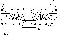
Figure 21 represents to want portion's structure as the polarized light controller 4 of the Megneto-optical optical element of present embodiment.In Figure 21, selection and Fig. 1 and the same coordinate system of Fig. 2 (a) and (b).As shown in figure 21, the polarized light controller 4 of present embodiment has 1 Faraday rotator 21.Faraday rotator 21 has the roughly shape of rectangular parallelepiped, and has the surface 22,23 that is parallel to the XY face jointly.Near the incident light district 34 of incident beam, form non reflecting film 32 in the surface 22, near the light that light beam penetrates penetrates district 35, form non reflecting film 33.Other parts on surface 22 form total reflection film 30.And near penetrating the incident light district 39 of district 38 and light beam incident, the light that light beam penetrates forms non reflecting film 36, other parts formation total reflection film 31a, 31b in another surface 23 on surface 23.
Incide light beam on the Faraday rotator 21 from incident light district 34, penetrated district 38 from light behind total reflection film 31a, 30 alternating reflexs once to penetrate.Penetrate the light beams that penetrate in district 38 from light by plate 62 reflections that are reflected of 1/4 wavelength sheet 60, incide once more the Faraday rotator 21 from incident light district 39.Inciding light beam on the Faraday rotator 21 once more from incident light district 39 penetrates district 35 from light after by total reflection film 30,31b alternating reflex and penetrates.
On Faraday rotator 21, apply predetermined magnetic field by not shown permanent magnet.Near the incident light district 34 of Faraday rotator 21 zones become by+magnetic region A1 that the magnetization of Z direction constitutes whereby.The light of Faraday rotator 21 penetrates near district 38 and the incident light district 39 zones and becomes magnetic region A2 by constituting with the equidirectional magnetization of magnetic region A1.The light of Faraday rotator 21 penetrates near the district 35 zones and becomes magnetic region A3 by constituting with the equidirectional magnetization of magnetic region A1, A2.Zone between the magnetic region of Faraday rotator 21 A1 and magnetic region A2 becomes the magnetic region B1 that constitutes by the magnetization with magnetic region A1, A2, A3 reverse (Z direction).The magnetic region A2 of Faraday rotator 21 and the zone between the A3 of magnetic region form the magnetic region B2 by constituting with the equidirectional magnetization of magnetic region B1.Between magnetic region A1 zone and B1 zone, magnetic region, form domain wall I1, between magnetic region A2 zone and B1 zone, magnetic region, form domain wall I2.Between magnetic region A2 zone and B2 zone, magnetic region, form domain wall I3, between magnetic region A3 zone and B2 zone, magnetic region, form domain wall I4.
When apply near B1 zone, magnetic region by not shown electromagnet predetermined strength+during the magnetic field of Z direction, domain wall I1, I2 move to direction near each other, the width of magnetic region B1 narrows down according to the intensity that applies magnetic field.Similarly, when near B2 zone, magnetic region, apply predetermined strength+during the magnetic field of Z direction, domain wall 13,14 moves to direction near each other, the width of magnetic region B2 narrows down according to the intensity that applies magnetic field.
The polarized light rotation angle that produces when light transmits in Faraday rotator 21, the difference of the light path in the magnetic region B (B1, B2) that light path in the magnetic region A (A1, A2, A3) that constitutes with magnetization by+Z direction and the magnetization by-Z direction constitute is proportional.Therefore keep incident light district 34 to be positioned at magnetic region A1 on one side, light penetrates district 38 and incident light district 39 is positioned at magnetic region A2, light penetrates district 35 and is positioned at this state of magnetic region A3, on one side by utilize electromagnet for example edge+Z direction apply variable magnetic field, domain wall I1, I2, I3, I4 are moved, change the width of magnetic region B1, B2, light path and the poor of the light path in the B of magnetic region in the A of magnetic region are changed, thereby can make the polarized light rotation angle variable.In the present embodiment, among the figure of a Faraday rotator 21 among left part and the figure right side be divided into other Faraday rotator of branch and play a role.If make from light with another reflector plate and to penetrate the beam reflection that district 35 penetrates, reenter and be mapped in the Faraday rotator 21, a Faraday rotator 21 is played a role as the Faraday rotator of 3 (or more than three).Therefore can constitute unlimited following-up type polarized light controller with 1 Faraday rotator 21.In addition according to present embodiment, can similarly realize small-sized, low power consumption electric power and at a high speed and the Megneto-optical optical element of low price with the 2nd embodiment.
Figure 22 represents the variation of the Megneto-optical optical element structure of present embodiment.As shown in figure 22, for example 2 Faraday rotator 20a, 20b of the polarized light controller 4 of this variation ' have.The mode faced disposes so that the light of Faraday rotator 20a penetrates that 1/4 wavelength sheet 60 in the incident light district 34b clamping of district 35a and Faraday rotator 20b for two Faraday rotator 20a, 20b.After penetrating the light transmission 1/4 wavelength sheet 60 that district 35a penetrates from the light of Faraday rotator 20a, be incident to the incident light district 34b of Faraday rotator 20b.Faraday rotator 20a has surperficial 22a, 23a common parallel with the XY face and that face one another.Near the incident light district 34a that the light of the optical fiber 58 that carries lens is injected, form non reflecting film 32a among the surperficial 22a, at the other parts formation total reflection film 30a of surperficial 22a.Near penetrating district 35a, light forms non reflecting film 33a among another surperficial 23a, at the other parts formation total reflection film 31a of surperficial 23a.The end 42a of yoke of electromagnet that applies variable magnetic field on Faraday rotator 20a is so that the back side of the contiguous total reflection film 30a of its top end face 42c mode relative with the back side of total reflection film 30a and disposing.The other end 42b of yoke disposes with the back side of its top end face 42d contiguous total reflection film 31a of mode relative with the back side of total reflection film 31a.The top end face 42c of end 42a and the top end face 42d of end 42b Faraday rotator 20a with clamping and the mode that faces one another disposes.
Faraday rotator 20b has surperficial 22b, the 23b that is parallel to the XY face jointly and faces one another.Near incident light district 34b, form non reflecting film 32b among the surperficial 22b, at the other parts formation total reflection film 30b of surperficial 22b.In optical fiber 59 1 sides that have lens, near penetrating district 35b, the light that light penetrates forms non reflecting film 33b among another surperficial 23b, at the other parts formation total reflection film 31b of surperficial 23b.On Faraday rotator 20b, apply variable magnetic field electromagnet yoke an end 42e so that its top end face 42g mode relative with the back side of total reflection film 30b dispose near the back side of total reflection film 30b.The other end 42f of yoke so that its top end face 42h mode relative with the back side of total reflection film 31b dispose near the back side of total reflection film 31b.The top end face 42h clamping of the top end face 42g of end 42e and end 42f Faraday rotator 20b and configuration with facing one another.
Permanent magnet 67b is configured in end 42e's+directions X, permanent magnet 68b be configured in end 42e-directions X.The direction of magnetization of permanent magnet 67b is+the Z direction that the direction of magnetization of permanent magnet 68b is-the Z direction.In addition, end 42f-directions X configuration permanent magnet 69b, and further permanent magnet 69b-directions X configuration permanent magnet 66b.The direction of magnetization of permanent magnet 69b is-the Z direction.The direction of magnetization of permanent magnet 66b is+the Z direction.Near the incident light district 34b of Faraday rotator 20b zone becomes by+magnetic region A3 that the magnetization of Z direction constitutes, and light penetrates near the district 35b zone and becomes magnetic region A4 by constituting with the equidirectional magnetization of magnetic region A3.Zone between magnetic region A3 and the magnetic region A4 becomes the magnetic region B2 by constituting with magnetic region A3, A4 magnetic reversal.Between magnetic region A3 and magnetic region B2, form domain wall I3, between magnetic region B2 and magnetic region A4, form domain wall I4.In the formation of this example, the result is corresponding magnetic region A3 configuration permanent magnet 66b, corresponding magnetic region B2 configuration permanent magnet 68b, 69b, corresponding magnetic region A4 configuration permanent magnet 67b.
Though the polarized light controller 4 of this variation ' compare with polarized light controller 4 shown in Figure 21, essential two Faraday rotator 20a, 20b do not need refinement correctly to adjust the reflector plate 62 of angle.So polarized light controller 4 ' have assembling easily, and realize the advantage of miniaturization.Though polarized light controller 4 ' be the two-period form structure with two Faraday rotator 20a, 20b in addition also can be by with three or above Faraday rotator formation three sections or above multi-segment structure.
In the present embodiment with polarized light controller 4,4 ' for exemplifying example explanation Megneto-optical optical element, yet connect into multistage by the device that shakes at the front and back of each Faraday rotator configuration polarizer, also can realize utilizing the variable filter of the wavelength dependency of polarized light rotation angle, reflection can make the variable amplitude of polarized light rotation angle easily broaden to present embodiment by utilizing repeatedly, so also be applicable to as variable filter.
The 5th embodiment
Then describe with regard to the Megneto-optical optical element of the present invention's the 5th embodiment with Figure 23.Though in embodiment hereto, be so that be to exemplify example, the invention is not restricted to this with the variable Megneto-optical optical element of electromagnet.For example also can be without electromagnet, by adjusting the position of permanent magnet, the polarized light rotation angle is adjusted to optimum value after, fix this permanent magnet, also be applicable to optoisolator or light circulator thus.Adopt this structure, can reduce the insertion loss, and can finely tune the polarized light rotation angle, therefore can realize high-performance two-period form optoisolator, the light circulator that isolation performance is high.As concrete formation, for example can use the elements combination of known polarizer of settled the present and Faraday rotator at the front and back of magneto-optical crystal configuration polarizer.Also can pass through mobile permanent magnet, and removable magnetic region.
Figure 23 represents the structure as the optoisolator 5 of the Megneto-optical optical element of present embodiment.As shown in figure 23, according to present embodiment, for example for the structure shown in Figure 21, replace 1/4 wavelength sheet 60 with polarizer 81, and before non reflecting film 32 after (light incident side) and the non reflecting film 33 (light emitting side) further dispose polarizer 80,82 respectively.With the surface 23 of Faraday rotator 21 in begin to dispose in turn permanent magnet 84,85 on left field is faced among the figure the position from a left side.The direction of magnetization of permanent magnet 84 is+the Z direction that the direction of magnetization of permanent magnet 85 is-the Z direction.With the surface 23 of Faraday rotator 21 in begin to dispose in turn permanent magnet 87,88 on right side area is faced among the figure the position from a left side.The flow direction of permanent magnet 87 inside is-the Z direction that the flow direction of permanent magnet 88 inside is+the Z direction.And with the surface 22 of Faraday rotator 21 in configuration permanent magnet 86 near face the central portion the position.The direction of magnetization of permanent magnet 86 is+the Z direction.Each permanent magnet 84,85,86,87 and 88 is fixing after adjusting the position, and domain wall I1, I2, I3 and I4 in the Faraday rotator 21 are configured on the desirable position.According to this variation,, simplify and cost degradation so can reach assembling because only just can realize 2 segmentation optoisolator or light circulators with a magneto-optical crystal.Equally also can realize 3 segmentations or above optoisolator or light rotation circulator.
In addition, as the magneto-optical crystal that can utilize in the 1st to the 5th embodiment, must on the vertical direction of apparent surface 22,23, easy magnetizing axis be arranged.Though this is because in the above-described embodiment, just the component (Z durection component) of surface 22,23 vertical direction is illustrated at the external magnetic field instrument, but in having the magnetooptics crystal of such perpendicular magnetization, the magnetic field of the component of vertical direction has determined the magnetic region structure haply.Though also there is the magnetic-field component (directions X component and Y durection component) of direction in the face parallel with surperficial 22,23, little to the magnetic region structure influence.
The 6th embodiment
The Megneto-optical optical element of the present invention's the 6th embodiment then is described with Figure 24.Figure 24 represents the structure as the polarized light controller 6 of the Megneto-optical optical element of present embodiment.The employing coordinate system identical in Figure 24 with Fig. 1 and Fig. 2.As shown in figure 24, the polarized light controller 6 of present embodiment has 1 Faraday rotator 24.In the present embodiment, as described later, adopt to make the magnetization rotation and the magnetization rotation mode of control polarized light rotation angle.Therefore, Faraday rotator 24 usefulness are made by the magnetic garnet monocrystal film that the thermal treatment of carrying out under 1000 ℃ of temperature up and down about a few hours disappears the growing response magnetic anisotropy.
Polarized light controller 6 has permanent magnet 46,47, comprise yoke (both ends 42a, the 42b of yoke only are shown in Figure 24) and be wound on the electromagnet of the coil on the yoke.Permanent magnet 46 is configured in Faraday rotator 24-directions X, permanent magnet 47 be configured in Faraday rotator 24+directions X.The direction of magnetization of permanent magnet 46,47 all is+directions X.An end 42a of the yoke of electromagnet so that its top end face 42c mode relative with the back side of the total reflection film 30 that on a surface of Faraday rotator 24, forms dispose near the back side of total reflection film 30.The other end 42b of yoke so that its top end face 42d mode relative with the back side of the total reflection film 31 that on another surface of Faraday rotator 24, forms dispose near the back side of total reflection film 31.The top end face 42c of end 42a and the top end face 42d of end 42b Faraday rotator 24 with clamping and the mode that faces one another disposes.
When in magnet spool, not flowing through electric current, Faraday rotator 24 is applied+magnetic field of directions X with the intensity more than the saturation magnetic field by permanent magnet 46,47.Therefore, Faraday rotator 24 is in the state of saturated magnetization in the magnetization of+directions X.Because faraday's rotation angle depends on magnetized Z durection component, so the faraday's rotation angle when not flowing through electric current in coil roughly is 0 °.When in coil, flowing through electric current, for example applied+variable magnetic field of Z direction by electromagnet by the yoke both ends 42a of Faraday rotator 24, zone that 42b clips.That is, be applied on this zone of Faraday rotator 24 the external magnetic field for apply by permanent magnet 46,47+magnetic field of directions X and by electromagnet apply+resultant magnetic field of the variable magnetic field of Z direction.By the electric current that flows in coil is changed, the direction of the resultant magnetic field with the above intensity of saturation magnetic field is changed, thus in by the yoke both ends 42a of Faraday rotator 24, zone that 42b clips, keep the state of saturated magnetization on one side, (arrow among the figure a) changes magnetized Z durection component to change magnetized direction on one side.Because faraday's rotation angle is along with magnetized Z durection component changes, so, can adjust faraday's rotation angle by being controlled at the moving electric current of coil midstream.At this, in the incident light district 34 and near the zone the light ejaculation district 35 of Faraday rotator 24, apply the magnetic field that electromagnet produces hardly.Therefore the direction of magnetization (the arrow b among the figure) near the zone incident light district 34 and light ejaculation district 35 all keeps+directions X.
In the present embodiment, the direction of magnetization near the zone the incident light district 34 of Faraday rotator 24 becomes identical with the direction of magnetization that light penetrates near the zone of distinguishing 35.Therefore because the polarized light rotation angle is identical in as whole light paths of the light beam of directional light, so by Faraday rotator 24 post-concentrations in output with optical fiber in the time do not produce diffraction loss.And in the present embodiment, on Faraday rotator 24, there is not domain wall I.Therefore,, domain wall I do not penetrate district 35, so the amplitude of fluctuation of inserting loss is diminished because also not passing incident light district 34 and light certainly.Therefore the Megneto-optical optical element of present embodiment goes for requiring the low and little polarized light controller of loss variation amplitude of loss.
In addition, in the present embodiment, because both ends 42a, the 42b of yoke so can apply variable magnetic field effectively on Faraday rotator 24, can make the Megneto-optical optical element miniaturization, the electric power low consumptionization respectively near total reflection film 30,31 configurations.And in the present embodiment, because Faraday rotator 24 uses in the saturated magnetization zone usually, repeatability makes the polarized light rotation angle change well so can not produce hysteresis.
Adopted the relatively magnetization rotation mode of difficulty of miniaturization and low power consumptionization in the present embodiment.But, elongated because in the present embodiment by repeatedly reflecting the light path that makes in the Faraday rotator 24, thus even the magnetized anglec of rotation is little, also can obtain big polarized light rotation angle, and can obtain the variable range of polarized light rotation angular width.Therefore,, promptly use the magnetization rotation mode, also can realize more small-sized and Megneto-optical optical element low power consumption according to present embodiment.
In addition, in above-mentioned the 1st to the 6th embodiment, must make the little degree that does not overlap each other to the light beam of multipath reflection of beam diameter of light beam.But because when beam diameter diminishes, light beam is because of diffraction expansion easily, so must be set at suitable value.Though thickness, light that suitable beam diameter value is subjected to magneto-optical crystal are to about the incident angle of magneto-optical crystal etc., the beam diameter about practical last 40~100 μ m is suitable.Optical system as the light beam that uses so little beam diameter, except can using optical system, also can use the optical fiber 58,59 that has adopted the band lens that make lens and optical fiber integration as shown in figure 22 like that or make the optical system of core expansion type optical fiber that the core of the head portion of optical fiber enlarges etc. by heating as Fig. 5 and optical fiber as shown in Figure 19 50,52 and lens 54,56 separate configuration.The optical fiber of band lens fiber 58,59 or core expansion type is compared with the occasion of separate configuration lens, is suitable for miniaturization, and or make easily assembled.
In addition, " Megneto-optical optical element " in this manual not only refers to the component type parts that are made of magneto-optical crystal, magnetic field applying mechanism etc., and refers to comprise lens, optical waveguide mechanism (optical fiber or optical waveguide) as required, is used to flow through the electrode of electric current and holds the parts of their basket etc.
The invention is not restricted to above-mentioned embodiment, various modification can be arranged.
Though for example in the above-described embodiment, be the example explanation as Megneto-optical optical element with polarized light controller and photomodulator etc., the invention is not restricted to this.Also applicable to by the electric current that flows through is changed, control other the Megneto-optical optical element such as variable optical attenuator of the damping capacity of light changeably in the coil 44 of electromagnet 40.When inciting somebody to action structure applications for example shown in Figure 5 in variable optical attenuator, also can between lens 54 and Faraday rotator 20, dispose polarizer, between Faraday rotator 20 and lens 56, dispose analyzer.
In addition, if can form the magnetic region structure same with above-mentioned embodiment in Faraday rotator 20, disposing permanent magnet by any means can.For example also can make two permanent magnets contiguous and be configured in respectively on each top of end 42a, 42b with mutually reverse magnetic pole.
In addition, though be that the example that disposes for permanent magnet 46,47 contact (approaching) yokes 42 illustrates in the above-mentioned embodiment, the invention is not restricted to this.For example make permanent magnet 46,47 leave yoke 42, respectively Faraday rotator 20 ± dispose on the directions X, in Faraday rotator 20, form the magnetic region identical and construct also passable with above-mentioned embodiment.
Though in the above-described embodiment, be that example illustrates as Faraday rotator with magnetic garnet monocrystal film with the growth of LPE method, the invention is not restricted to this.For example also can use fusion method, FZ method, magnetic garnet that solid phase method etc. are made or orthoferrites etc.
Claims (10)
1, a kind of Megneto-optical optical element is characterized in that, comprising:
Have the opposed the 1st and the magneto-optical crystal on the 2nd surface;
Be configured in the 1st total reflection portion at least a portion of above-mentioned the 1st face side of above-mentioned magneto-optical crystal;
Be configured in the 2nd total reflection portion at least a portion of above-mentioned the 2nd face side of above-mentioned magneto-optical crystal;
Light is to the incident light district of above-mentioned magneto-optical crystal incident;
Penetrated the district by the above-mentioned light of the above-mentioned the 1st and the 2nd total reflection portion alternating reflex from the light that above-mentioned magneto-optical crystal penetrates;
So that penetrate the mode that does not have domain wall in the district applies magnetic field to above-mentioned magneto-optical crystal magnetic field applying mechanism at above-mentioned incident light district and above-mentioned light.
2, Megneto-optical optical element as claimed in claim 1 is characterized in that:
Above-mentioned magnetic field applying mechanism is so that apply magnetic field with the consistent mode of direction of magnetization that above-mentioned light penetrates in the district to above-mentioned magneto-optical crystal at above-mentioned incident light district.
3, Megneto-optical optical element as claimed in claim 1 or 2 is characterized in that:
Above-mentioned incident light district is configured on above-mentioned the 1st surface,
Above-mentioned light penetrates the district and is configured on above-mentioned the 2nd surface.
4, Megneto-optical optical element as claimed in claim 1 or 2 is characterized in that:
Above-mentioned incident light district and above-mentioned light penetrate the district and all are configured on above-mentioned the 1st surface.
5, as any described Megneto-optical optical element in the claim 1 to 4, it is characterized in that:
Above-mentioned magneto-optical crystal has predetermined easy magnetizing axis, comprises that folk prescription by being parallel to above-mentioned easy magnetizing axis is to magnetic region A that magnetization constitutes and the magnetic region B by constituting with the rightabout magnetization of the direction of magnetization of above-mentioned magnetic region A.
6, Megneto-optical optical element as claimed in claim 5 is characterized in that:
Above-mentioned magnetic field applying mechanism comprise make the magnetic-field component that is applied to the above-mentioned predetermined direction on the above-mentioned magneto-optical crystal be the electromagnet of 0 position changeable and respectively be formed at above-mentioned magneto-optical crystal on a plurality of magnetic regions corresponding and each at least respectively disposes 1 permanent magnet.
7, as any described Megneto-optical optical element in the claim 1 to 4, it is characterized in that:
Above-mentioned magnetic field applying mechanism is included in the electromagnet of at least one permanent magnet that applies fixed magnetic field on the above-mentioned magneto-optical crystal and the variable magnetic field that applies the direction different with the direction in said fixing magnetic field on above-mentioned magneto-optical crystal, so that the resultant magnetic field in above-mentioned variable magnetic field and said fixing magnetic field has the mode of the above intensity of the saturation magnetic field of above-mentioned magneto-optical crystal, make the Strength Changes of above-mentioned variable magnetic field, the direction of magnetization of above-mentioned magneto-optical crystal is changed.
8, a kind of Megneto-optical optical element is characterized in that, comprising:
Have the opposed the 1st and the magneto-optical crystal on the 2nd surface;
Be configured in the 1st total reflection portion at least a portion of above-mentioned the 1st face side of above-mentioned magneto-optical crystal;
Be configured in the 2nd total reflection portion at least a portion of above-mentioned the 2nd face side of above-mentioned magneto-optical crystal;
Light is to the incident light district of above-mentioned magneto-optical crystal incident;
Above-mentioned light by the above-mentioned the 1st and the 2nd total reflection portion surface alternating reflex penetrates the district from the light that above-mentioned magneto-optical crystal penetrates;
The magnetic field applying mechanism, this magnetic field applying mechanism is included in electromagnet that applies variable magnetic field on the above-mentioned magneto-optical crystal and at least one permanent magnet that applies fixed magnetic field on above-mentioned magneto-optical crystal, and wherein this electromagnet comprises having near end of above-mentioned the 1st total reflection portion back side configuration with near the yoke of the other end of above-mentioned the 2nd total reflection portion back side configuration be wound on coil on the above-mentioned yoke.
9, Megneto-optical optical element as claimed in claim 8 is characterized in that:
Above-mentioned magneto-optical crystal has predetermined easy magnetizing axis, comprises that folk prescription by being parallel to above-mentioned easy magnetizing axis is to magnetic region A that magnetization constitutes and the magnetic region B by constituting with the rightabout magnetization of the direction of magnetization of above-mentioned magnetic region A.
10, Megneto-optical optical element as claimed in claim 8 is characterized in that:
The direction of above-mentioned variable magnetic field is different mutually with the direction in said fixing magnetic field,
Above-mentioned magnetic field applying mechanism changes the direction of magnetization of above-mentioned magneto-optical crystal so that the resultant magnetic field in above-mentioned variable magnetic field and said fixing magnetic field has the Strength Changes that the mode of the above intensity of the saturation magnetic field of above-mentioned magneto-optical crystal makes above-mentioned variable magnetic field.
Applications Claiming Priority (4)
| Application Number | Priority Date | Filing Date | Title |
|---|---|---|---|
| JP2003305755 | 2003-08-29 | ||
| JP305755/2003 | 2003-08-29 | ||
| JP2004212621A JP2005099737A (en) | 2003-08-29 | 2004-07-21 | Magnetooptic optical component |
| JP212621/2004 | 2004-07-21 |
Publications (1)
| Publication Number | Publication Date |
|---|---|
| CN1601333A true CN1601333A (en) | 2005-03-30 |
Family
ID=34467349
Family Applications (1)
| Application Number | Title | Priority Date | Filing Date |
|---|---|---|---|
| CN200410087471.7A Pending CN1601333A (en) | 2003-08-29 | 2004-08-27 | Megneto-optical optical element |
Country Status (3)
| Country | Link |
|---|---|
| US (1) | US7002732B2 (en) |
| JP (1) | JP2005099737A (en) |
| CN (1) | CN1601333A (en) |
Cited By (4)
| Publication number | Priority date | Publication date | Assignee | Title |
|---|---|---|---|---|
| CN105044933A (en) * | 2015-08-06 | 2015-11-11 | 深圳市创鑫激光股份有限公司 | Optical isolator, laser output head and laser |
| CN105044935A (en) * | 2015-08-07 | 2015-11-11 | 中国科学院光电研究院 | Electromagnetic induction faraday optical rotator |
| CN107965730A (en) * | 2016-10-19 | 2018-04-27 | 黑拉许克联合股份有限公司 | Lighting apparatus for vehicle |
| CN109085702A (en) * | 2018-09-15 | 2018-12-25 | 西安奇芯光电科技有限公司 | Polarization fading device and polarization fading method |
Families Citing this family (4)
| Publication number | Priority date | Publication date | Assignee | Title |
|---|---|---|---|---|
| JP4972982B2 (en) | 2006-04-17 | 2012-07-11 | 富士通株式会社 | Polarization control device and polarization operation device |
| JP5866991B2 (en) | 2011-11-14 | 2016-02-24 | 富士ゼロックス株式会社 | Image forming apparatus |
| JP6294796B2 (en) * | 2014-09-01 | 2018-03-14 | 日本電信電話株式会社 | Optical deflector and apparatus including optical deflector |
| US20170176781A1 (en) * | 2015-12-18 | 2017-06-22 | Electro-Optics Technology, Inc. | Single and multi-stage high power optical isolators using a single polarizing element |
Family Cites Families (4)
| Publication number | Priority date | Publication date | Assignee | Title |
|---|---|---|---|---|
| US3420601A (en) | 1965-06-24 | 1969-01-07 | American Optical Corp | Materials and structures for optical faraday rotation devices |
| US4239337A (en) | 1979-06-08 | 1980-12-16 | Bell Telephone Laboratories, Incorporated | Magneto-optic modulator using dielectric mirrors |
| JP2815509B2 (en) | 1992-07-31 | 1998-10-27 | 富士通株式会社 | Optical attenuator |
| US5657151A (en) | 1993-12-09 | 1997-08-12 | Lucent Technologies Inc. | Polarization scrambler/modulator |
-
2004
- 2004-07-21 JP JP2004212621A patent/JP2005099737A/en not_active Withdrawn
- 2004-08-24 US US10/923,873 patent/US7002732B2/en not_active Expired - Fee Related
- 2004-08-27 CN CN200410087471.7A patent/CN1601333A/en active Pending
Cited By (5)
| Publication number | Priority date | Publication date | Assignee | Title |
|---|---|---|---|---|
| CN105044933A (en) * | 2015-08-06 | 2015-11-11 | 深圳市创鑫激光股份有限公司 | Optical isolator, laser output head and laser |
| CN105044935A (en) * | 2015-08-07 | 2015-11-11 | 中国科学院光电研究院 | Electromagnetic induction faraday optical rotator |
| CN107965730A (en) * | 2016-10-19 | 2018-04-27 | 黑拉许克联合股份有限公司 | Lighting apparatus for vehicle |
| CN109085702A (en) * | 2018-09-15 | 2018-12-25 | 西安奇芯光电科技有限公司 | Polarization fading device and polarization fading method |
| CN109085702B (en) * | 2018-09-15 | 2020-09-18 | 西安奇芯光电科技有限公司 | Polarization attenuator and polarization attenuation method |
Also Published As
| Publication number | Publication date |
|---|---|
| US20050146769A1 (en) | 2005-07-07 |
| US7002732B2 (en) | 2006-02-21 |
| JP2005099737A (en) | 2005-04-14 |
Similar Documents
| Publication | Publication Date | Title |
|---|---|---|
| CN1167970C (en) | Tunable optical filter | |
| CN1601333A (en) | Megneto-optical optical element | |
| CN103424809B (en) | Polarization independent optical isolator | |
| US6718082B2 (en) | Solid-State optical wavelength switches | |
| JPH10161076A (en) | Optical device using magnetooptical effect | |
| CN104020623B (en) | Background-free wave beam direction controller based on split ring structure | |
| US6301425B1 (en) | Magnetically tunable optical attenuator and method of attenuating signals | |
| Xie et al. | Near‐zero‐sidelobe optical subwavelength asymmetric focusing lens with dual‐layer metasurfaces | |
| CN1651979A (en) | Magneto-optical component | |
| JPH11249095A (en) | Faraday rotator | |
| US6833941B2 (en) | Magneto-optic optical device | |
| CN1308739C (en) | Farady rotator and optical device comprising same, and antireflection film and optical device comprising same | |
| CN103228826A (en) | Bismuth-substituted rare earth iron garnet crystal film and optical isolator | |
| CN1609659A (en) | Reflective optical parts | |
| WO2017140143A1 (en) | Photonic crystal cross-junction waveguide-based magnetically-controlled one-out-of-two optical path switch | |
| JP4868311B2 (en) | Faraday rotator for short wavelength light and optical isolator equipped with the Faraday rotator | |
| WO2006080496A1 (en) | Variable optical attenuator | |
| CN1639615A (en) | Optical switch | |
| CN208224650U (en) | Optical waveguide and amplitude modulator | |
| JPS5854315A (en) | Optical isolator | |
| CN105044934A (en) | Optical isolator, laser output head and laser equipment | |
| JP4286024B2 (en) | Magnetic garnet material, Faraday rotator, optical device, method for producing bismuth-substituted rare earth iron garnet single crystal film, and crucible | |
| JPS62242915A (en) | Optical isolator and its manufacture | |
| JPH0415199B2 (en) | ||
| CN1818743A (en) | Farady rotator and optical device comprising same, and antireflection film and optical device comprising same |
Legal Events
| Date | Code | Title | Description |
|---|---|---|---|
| C06 | Publication | ||
| PB01 | Publication | ||
| C10 | Entry into substantive examination | ||
| SE01 | Entry into force of request for substantive examination | ||
| C02 | Deemed withdrawal of patent application after publication (patent law 2001) | ||
| WD01 | Invention patent application deemed withdrawn after publication |
Open date: 20050330 |