CN1543579A - Twisted nematic micropolarizer and its method of manufacturing - Google Patents
Twisted nematic micropolarizer and its method of manufacturing Download PDFInfo
- Publication number
- CN1543579A CN1543579A CNA028064836A CN02806483A CN1543579A CN 1543579 A CN1543579 A CN 1543579A CN A028064836 A CNA028064836 A CN A028064836A CN 02806483 A CN02806483 A CN 02806483A CN 1543579 A CN1543579 A CN 1543579A
- Authority
- CN
- China
- Prior art keywords
- plate
- liquid crystal
- polyimide
- nematic liquid
- space
- Prior art date
- Legal status (The legal status is an assumption and is not a legal conclusion. Google has not performed a legal analysis and makes no representation as to the accuracy of the status listed.)
- Pending
Links
Images


Classifications
-
- G—PHYSICS
- G02—OPTICS
- G02B—OPTICAL ELEMENTS, SYSTEMS OR APPARATUS
- G02B5/00—Optical elements other than lenses
- G02B5/30—Polarising elements
-
- G—PHYSICS
- G02—OPTICS
- G02B—OPTICAL ELEMENTS, SYSTEMS OR APPARATUS
- G02B5/00—Optical elements other than lenses
- G02B5/30—Polarising elements
- G02B5/3016—Polarising elements involving passive liquid crystal elements
-
- G—PHYSICS
- G02—OPTICS
- G02B—OPTICAL ELEMENTS, SYSTEMS OR APPARATUS
- G02B5/00—Optical elements other than lenses
- G02B5/30—Polarising elements
- G02B5/3025—Polarisers, i.e. arrangements capable of producing a definite output polarisation state from an unpolarised input state
- G02B5/3033—Polarisers, i.e. arrangements capable of producing a definite output polarisation state from an unpolarised input state in the form of a thin sheet or foil, e.g. Polaroid
Abstract
The invention is a method for creating a micropolarizer, including providing a first plate having a first and a second surface, providing a second plate having a first and a second surface. Then coating a polyimide on each of the first surface of the two plates followed by rubbing the polyimide coated upon the first surface of the first plate along a predetermined direction and rubbing the polyimide coated upon the first surface of the second plate along a direction having a predetermined angle in relation to the predetermined direction. An alignment process includes aligning the first plate and the second plate having the first surface of the first plate and the first surface of the second plate facing each other thereby creating a space there between. In conclusion there is a filling of a liquid crystal between the space whereby a cell, or film is created.
Description
The cross reference of related application
The provisional application 60/261,135 that the application relates to January 12 calendar year 2001 and submits to, this application are drawn at this and are reference.
Background of invention
This instructions has been summarized and has been related to a kind of little polarizer (μ Pol based on twisted-nematic phase (TN) liquid crystal
TM) exploitation and the invention of manufacturing.
Reveo company has created, has developed and gone on the market a kind of dimension display technologies of utilizing little polarization (μ Pol) plate, and in this technology, the polarizer with vertical polarization cross hatch of patterning is connected use with polarized glass.In this technology, polyvinyl alcohol (PVA) (PVA) λ/2 delayers become the basis of setting up μ Pol array.The basis of this μ Pol array depends on the π phase shift that PVA causes.μ Pol sets up by this way, and promptly it is by band π phase shift or do not form with the line of the alternate intervals of π phase shift, as shown in Figure 1.
The advantage of this μ Pol comprises:
Simple processing procedure;
Lower cost;
Higher output.
But PVA base μ Pol has following shortcoming:
Owing to phase shift mechanism has relatively poor spectral characteristic;
Relative thicker film thickness;
Relatively low spatial resolution;
Be difficult to control line thickness;
Relatively poor heat-resisting and moisture resistance.
The invention describes the method that another makes high-quality μ Pol, it can eliminate the problems referred to above basically.
Summary of the invention
The present invention is a kind of method of making little polarizer, comprising: first plate with first and second surfaces is provided, second plate with first and second surfaces is provided.Then, on the first surface of each plate, be coated with polyimide, be coated on polyimide on the first surface of first plate along predetermined direction friction afterwards, and be coated on the polyimide on the first surface of second plate along a direction friction that becomes predetermined angular with described predetermined direction.One calibration/alignment procedures comprises calibration first plate and second plate, and the first surface of first plate and the first surface of second plate are faced with each other, and forms a space thus between the two.At last, filling liquid crystal in this space forms a structure cell or film thus.
The accompanying drawing summary
Fig. 1 is based on the sketch of the PVA delayer of μ Pol technology;
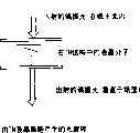
Fig. 2 is the optically-active by TN liquid crystal structure cell;
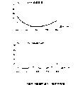
Fig. 3 is the transmissivity-wavelength curve of VA film and TN structure cell;
Fig. 4 is the sketch of TN base μ Pol;
Fig. 5 is the sketch of the TN base μ Pol that makes by the UV mask method;
Fig. 6 is the sketch of the TN base μ Pol that made by E-field calibration method;
Fig. 7 is the sketch of the TN base μ Pol that made by multiple rubbing manipulation;
Fig. 8 is the sketch of the TN base μ Pol with 260 μ m live widths that made by two step UV exposure methods;
Fig. 9 is the sketch of the TN base μ Pol with 60 μ m live widths that made by multiple rubbing manipulation;
Figure 10 utilizes flexible linear polarizer as a substrate, with the sketch of non-birefringent plate (non-briefringent) as the TN of another substrate base μ Pol;
Figure 11 is the sketch that directly is produced on the TN-μ Pol on the LC display;
Figure 12 is the sketch of 45 ° of little polarizers;
Figure 13 is the sketch of the TN-μ Pol of horizontal alignment;
Figure 14 is the sketch of TN-μ Pol that is used for the vertical alignment of vertical display element or sub-pixel column;
Figure 15 is the sketch of the chessboard TN-μ Pol of level and homeotropic alignment.
Detailed description of the present invention
The principle of TN liquid crystal
When twisted-nematic phase (TN) structure cell satisfies the Mauguin condition, can think that the linearly polarized photon of incident rotates by liquid crystal molecule.For 90 ° TN structure cell, the Mauguin condition be 2 Δ nd>>λ, wherein d is the thickness of liquid crystal structure cell, λ is the incident light wavelength, Δ n represents birefringence.The TN film makes linear polarization of incident light axle half-twist, as shown in Figure 2.
In 90 ° of TN structure cells, liquid crystal molecule is orientated by this way, and promptly top layer is arranged in one direction, and the bottom homeotropic alignment.The optical activity of TN structure cell demonstrates than λ/much smaller wavelength dependency of 2 delayers.In other words, the bandwidth of TN structure cell far is wider than the bandwidth of delayer, as shown in Figure 3.Fig. 3 represents that PVA film and TN structure cell as the transmittance graph of the function of wavelength, wherein carry out the measurement of transmissivity by insertion PVA film and TN structure cell between paired parallel rays.The thickness of TN structure cell is 10 μ m, adopts polymerizable liquid-crvstalline CM428 and by the UV photocuring.
Compare with the thickness of the commercially available delayer 37.5 μ m that come from Polaroid, the TN film can be done thinlyyer, typically is in the scope of 5 μ m.This thin layer optimum is constructed high-resolution μ Pol.Usually, the liquid crystal material that is used in the display system has good heat-resisting and moisture resistance.In addition, if make the TN structure cell, then can peel off and can be transferred to other surface from glass substrate with the liquid crystal of polymerizable (but UV polymerization).
TN-μ Pol has the advantage of PVA μ Pol and has overcome the shortcoming of PVA μ Pol.The advantage of TN-μ Pol is as described below:
In wider wave, has good spectral characteristic;
Thin film thickness.By selecting big birefringent liquid crystal material, TN-μ Pol can do as thin as a wafer, and demonstrates very wide bandwidth characteristic;
Higher spatial resolution;
Less zone of transition;
Be easy to control live width;
Good heat-resisting and moisture resistance;
Processing is simple, low cost and high yield.
μ Pol based on the TN liquid crystal
If make the TN film patterning,, then produce a kind of new μ Pol, as shown in Figure 4 so that it has the lines with or without the alternate intervals of optical activity.
In active band shown in Figure 4, liquid crystal molecule is twisted into rotation polarization of incident light angle.But in passive band, liquid crystal molecule does not all reverse under isotropic phase or homogeneous phase or homophase, makes that it can not the rotatory polarization direction.
The processing of TN μ Pol
There is several method that TN is processed into μ Pol.Four kinds of main method that proposed are:
Two step UV exposures;
Arrange E field (electric field);
Multiple friction; With
Photoinduction is arranged.
Basic details about above-mentioned four kinds of disposal routes will be described below.
Two step UV exposure methods
The method adopts two step UV exposure programs to set up a μ Pol, and this μ Pol is made up of the nematic phase line that is in distortion attitude and isotropy attitude respectively.This method comprises the following steps:
On two glass plates, be coated with polyimide;
The rubbed polyimide coating;
Make a structure cell with described two glass plates, make the polyimide friction direction of one of them plate perpendicular to the polyimide friction direction of another plate;
Fill polymerisable nematic liquid crystal with light chirality concentration, thereby make a TN structure cell (film);
Cover the TN structure cell with a mask with transparent and zone of opacity of alternate intervals;
Under transparent region, nematic liquid crystal is aggregated into the crystal structure of a permanent distortion with UV light;
Remove mask;
Heat described structure cell to such an extent that be higher than the critical temperature of nematic phase isotropy, make those be become isotropic phase, thereby produce unwrung liquid crystal molecule by the not polymerization nematic phase experience critical state that opaque mask band covers.The nematic distorted-structure of polymerization remains unchanged.
At last, previous uncured nematic phase is polymerized to isotropic phase again.
The μ Pol of gained will have feature shown in Figure 5.This method is only to utilize polymerisable nematic liquid crystal to realize.
E-field (electric field) ranking method
In the method, prefabricated figuratum ITO electrode is applied the E field, to set up a μ Pol, this μ Pol comprises the nematic phase line that is in distortion and even matter structure respectively.Concrete program comprises:
Utilize photoetching process that an ito glass plate is formed pattern, the band that makes it have having of alternate intervals and not have ITO;
Be not coated with polyimide on the ito glass plate of patterning at the ito glass of patterning and another;
Rubbed polyimide on suitable direction;
Make a TN structure cell with above-mentioned two glass plates, the frictional direction of two glass plates is perpendicular to one another;
Fill nematic liquid crystal;
Apply the E field at banded ITO electrode, with the vertical alignment nematic liquid crystal.The nematic liquid crystal at each ITO place keeps the TN structure in the band.
The final structure of the μ Pol that constitutes by this method is shown among Fig. 6.
Multiple rubbing manipulation
The polyimide band of the patterning of setting up has the frictional direction of quadrature, makes that the liquid crystal arrangement in the band becomes distorted-structure, and the nematic phase in the phase adjacent band is arranged in even matter structure.Must use a kind of photoetching process can not cause the suitable polyimide of breaking-up to it.The step of this method is as follows:
On a glass substrate, be coated with polyimide (SE 7311 of Brewer Scientific or other suitable polyimide);
Unidirectional rubbed polyimide coating;
At the polyimide top coating photoresist (S 1815 of Microposit or other suitable photoresist) that is rubbed;
By photoetching process photoresist is produced pattern, thereby form the band of alternate intervals;
The remaining polyimide that do not covered of friction again on perpendicular to the direction of first frictional direction by photoresist;
Remove all photoresists by flushing in the acetone pond;
Make a structure cell with the glass plate of patterning and the polyimide glass plate of another unidirectional friction;
Fill structure cell with nematic liquid crystal, thereby form the alternately μ Pol of band of a kind of TN of having and even matter structure.
The photoinduction ranking method
Recently, the possibility of utilizing photosensitive alignment agent to arrange the LC structure cell receives a lot of concerns.Because it does not contact and be easy to patterning, this method has some advantages on the polymer film of friction.Also found some materials, had the ability of after being exposed to linear polarization UV light, arranging liquid crystal molecule as the polyimide and the azobenzene polymer of polyvinyl methyl cinnamic acid salt (PVMC), Polyvinylchloride (PVC), some polyimide, dyeing.Liquid crystal molecule is arranged on the direction perpendicular to the UV light polarization direction.As described below, there are several modes to realize TN μ Pol by the photoinduction ranking method.
A. utilize the two steps exposure of linear polarization UV light
For above-mentioned a lot of photoinduced arrangement materials, if they are exposed under the linear polarization UV light twice with different polarization directions, then they have the advantages that to make liquid crystal molecule arrange on the direction perpendicular to second exposure directions.Therefore, these characteristics provide a kind of mode of making TN μ Pol easily.Provide detailed steps below:
The material that will be suitable for the photoinduction arrangement is applied on two glass plates and oven dry subsequently;
Two glass plates are exposed under the linear polarization UV light;
By being placed on the mask on this glass plate, to wherein glass plate linear polarization UV light exposure, this linear polarization UV polarisation of light direction is perpendicular to initial polarization direction again;
Prepare a liquid crystal structure cell and fill with nematic liquid crystal.
Material for those liquid crystal can not be arranged corresponding to exposure for the second time rightly, can adopt following different program:
Suitable photoinduction arrangement material is applied on two glass plates toasts;
Wherein a glass plate is exposed under the linear polarization UV light;
By the mask that is placed on the glass plate another piece glass plate is exposed under the linear polarization UV light, accurately mobile mask half period, and use linear polarization UV light (polarization direction is perpendicular to initial polarization direction) exposure again;
Prepare a liquid crystal structure cell and fill with nematic liquid crystal.
B. utilize the exposure and the friction of linear polarization UV light
In the method, merge friction treatment and photoinduction ranking method and make TN μ Pol.Comprise following details:
Suitable photoinduction arrangement material is applied on two glass plates, carries out heat oven dry and mechanical friction then;
Pass mask irradiation glass substrate and glass substrate is wherein formed pattern by the light that is parallel to frictional direction with the polarization direction;
Make a structure cell with the glass plate of patterning and the polyimide plate of the even friction of another piece;
Fill the twisted-nematic phase material to form a μ Pol.
C. overall alignment
In the method, a spot of photoresist PVMC or azo dyes directly are mixed in the nematic liquid crystal.When shining with linearly polarized light, the nematic phase molecule is arranged perpendicular to the polarization direction.Be detailed steps below:
On polyimide coating to two glass plate, dry subsequently and rub;
Polyimide glass plate with friction is made a liquid crystal structure cell;
Fill nematic phase material;
See through mask with a branch of linearly polarized light irradiating liquid crystal structure cell, to form μ Pol perpendicular to frictional direction.
The final structure of above-mentioned μ Pol is with shown in Figure 7 identical.
Table I has been summarized the TN base μ Pol that makes with above-mentioned four kinds of methods respectively.
Table I. the summary table of the μ Pol by the processing of four kinds of methods
| Method | The application of recommending | Advantage | Shortcoming |
| Photomask | Be suitable for major applications | Technology does not simply have the good thermal stability low cost of ito glass | Lower resolution |
| The E-field | High-resolution applications | The thermal stability that high resolving power is good | Comparatively Fu Za technology may cause birefringence to need ito glass LC must have Δ ε ≠ 0 by nematic phase material in even matter attitude |
| Multiple friction | High-resolution applications | High resolving power does not have the good thermal stability of ito glass | Comparatively Fu Za technology may cause birefringence by nematic phase material in even matter attitude (ECB) |
| Photoinduction is arranged | High-resolution applications | The simple high resolving power of technology does not have the good thermal stability of ito glass | In even matter attitude (ECB), may cause the birefringence dyestuff must be in beyond the visible range by nematic phase material |
The photo of TN μ Pol
Provided the TN μ Pol photo that two width of cloth are observed with the cross polarizing microscope among the figure.Fig. 8 is the TN μ Pol of the 260 μ m live widths that make by two step UV exposure methods.White portion is represented the TN structure, and dark-coloured part is represented the isotropy attitude of nematic liquid crystal.Fig. 9 is another TN μ Pol of the 60 μ m live widths that make by multiple rubbing manipulation.Similarly, white portion is represented the TN structure, and the even matter of dark-coloured part expression is arranged.
Utilize passive linear polarizer as substrate
TN μ Pol also can utilize passive linear polarizer as one of them substrate of the patterning TN liquid crystal structure cell shown in the following accompanying drawing and constitute.Above-mentioned four kinds of each methods that is used to make TN μ Pol may be used to the method.The TN structure cell of gained will be a kind of flexible laminar films that can be applied to LCD display during fabrication.The process of constructing this TN μ Pol structure will depend on the selection to above-mentioned four kinds of methods.Figure 10 shows this building method.
If polymerisable TN liquid crystal is used for making, then the peelable version of TN μ Pol also can utilize this structure to realize.
The advantage of this method is to make the TN μ Pol of bulk or big volume, and is bonded to during fabrication on the LC display.This structure will replace common analyzer (being used in the polarizer of display output terminal).Anti-dazzle is measured and can be used on the non-birefringence substrate of this μ Pol structure, to reduce the dazzle on conventional LC display.
Directly on LCD, make TN μ Pol
It is to utilize display itself as a substrate and utilize a nonbirefringent layer as second substrate direct making TN μ Pol on the LC display that the another kind of preceding method is replaced.In preceding method, can directly on display, make TN μ Pol with each method for making (two step exposure methods, E long array method, multiple frictional direction method and photoinduction ranking method).The advantage of the method is and can accurately makes μ Pol as an additional step on display in the manufacturing process of LC display.
The type of TN-μ Pol
Except being used to make the method for TN μ Pol, the present invention also comprises the TN μ Pol of several types, comprising:
Two substrate-type: in the case, μ Pol adopts two glass substrate and the LC material of polymerizable not.Its advantage is to adopt LC cheaply.
1: two glass substrate of o modification has same thickness
O modification 2: do thinlyyer near the glass substrate of display, to reduce the visual angle by the parallax effect.
Single substrate-type: adopt polymerisable LC material, make and to remove a substrate.Removing of substrate makes and can increase the visual angle by the distance between the active component that reduces TN material and display.
TURP is remodeled: utilize the μ Pol of E field manufacture craft structure to switch between 2D and 3D.When not applying electric field, whole μ Pol causes all the light half-twists from display as single LC structure cell.When applying electric field, the LC material between patterning ITO electrode becomes even matter attitude and thereby rotatory polarization angle not.The user can be switched between 2D and 3D pattern by the switch that starts a control electric field.
The modification of E field method
A kind of modification of E field method will utilize polymerisable liquid crystal to make μ Pol as follows:
Carry out abovementioned steps, to make structure cell;
Fill structure cell with polymerisable LC material;
Apply the E field, make the LC material between the ITO electrode enter even matter attitude;
Utilize the polymerisable LC material of strong UV radiation curing;
Remove the E field;
Aftertreatment and cleaning.
45°TN?μPol
Existing application belongs to 0 ° of-90 ° of TN-μ Pol, 0 ° or 90 ° at the line rotatory polarization angle that wherein replaces.The μ Pol of another kind of type can utilize all above-mentioned methods to constitute, the line rotatory polarization angle-45 that wherein replaces ° or+45 °.Typical draw be shown in figure _ in.Orthogonal polarized light enters from the back of μ Pol, and according to the difference of row rotate-45 ° or+45 °.
It should be noted that at last μ Pol both can be vertical orientated, also can horizontal alignment.When adopting horizontal line, μ Pol accurately is arranged on the display horizontal line.When adopting perpendicular line, the location of μ Pol makes it accurately come on the vertical row of display.In addition, μ Pol distance between centers of tracks also can be designed to overlap with red, green, the blue pixel vertical row of display.At last, TN μ Pol can be designed to a kind of checkerboard pattern.This modification is shown in Figure 12-15.
Below list of references and the disclosure and apply for relevantly, and draw at this and to be reference: the U.S. Patent application US 5,537,144 of Sadeg Faris and US 5,844,717.S.M.Faris SID 91 digests P.840 in paper.World Scientific, 1990, the paper of the B.Bahadur that P232 delivers is entitled as " liquid crystal applications and uses thereof ".Clearendon Press Oxford, the book of the P.GDEGennes that published in 1993, " physics of liquid crystals " by name.T.Y.Marusii and Y.A.Reznikeov be at Mol.Mat., Vol.3, p.161, the paper on 1993.M.Schadt, H.Seiberle and A.Schuster be at Nature, Vol.381, P212, the paper on 1996.S.C.Jain and H.S.Kitzerrow be in Appl.Phys.Lett.64 (22), P.2946, and the paper on 1994.W.M.Gibbons, P.J.Shannon, S.T.Sun and B.J.Swetlin be at Nature, Vol351, p.49, the paper on 1991.G.P.Bryan-Brown and I.C.Sage be at Liquid Crystal, Vol.20, and No.6, p.825, the paper in 1996.K.Aoki is at American Chemical Society, Vol.8, p.1014, the paper on 1992.M.Schadt, H.Seiberie, A.Schuster and S.M.Kelly, at Jpn.J, Appl.Phys., Vol.34, p.L764, the paper in 1995.
Though more than described the preferred embodiments of the present invention, those skilled in the art it will be appreciated that, can make various changes and of equal value the replacement to the present invention under the prerequisite that does not break away from essence of the present invention and scope.Except a lot of modification, do not departing from the scope of the present invention down, can adopt concrete condition and material according to prompting of the present invention.Therefore, the invention is not restricted to specific embodiment, the present invention will comprise that all fall into the embodiment in the claim scope.
Claims (61)
1. method of making little polarizer comprises:
First plate with first and second surfaces is provided;
Second plate with first and second surfaces is provided;
On the first surface of each plate, be coated with polyimide;
Be coated on the polyimide on the first surface of first plate along predetermined direction friction;
Be coated on the polyimide on the first surface of second plate along a direction friction that becomes predetermined angular with described predetermined direction;
Calibrate first plate and second plate, the first surface of first plate and the first surface of second plate are faced with each other, between the two, form a space thus;
Filling liquid crystal in described space forms a structure cell or film thus.
2. the method for claim 1 is characterized in that, also comprises:
Utilize a mask transparent or zone of opacity that has alternately to cover described structure cell or film, will solidify energy selectivity ground thus and apply by this mask; With
Partly solidify a part of liquid crystal.
3. method as claimed in claim 2 is characterized in that, also comprises:
Remove mask; With
Described structure cell or film are heated to a temperature set-point, thus the uncured liquid crystal that is covered by zone of opacity are transformed into different phases.
4. the method for claim 1 is characterized in that, also comprises:
Uncured nematic phase is solidified into the isotropy attitude again.
5. the method for claim 1 is characterized in that, also comprises:
Basically solidify the material between the first surface of the first surface of first plate and second plate; With
Remove first plate; With
Remove second plate.
6. method as claimed in claim 2 is characterized in that:
Described curing comprises and applies ultraviolet light.
7. the method for claim 1 is characterized in that:
Described space has the distance that equates basically between the first surface of the first surface of first plate and second plate.
8. the method for claim 1 is characterized in that:
Described liquid crystal is a nematic liquid crystal.
9. method as claimed in claim 8 is characterized in that:
Described nematic liquid crystal is a polymerisable nematic liquid crystal.
10. the method for claim 1, it is characterized in that: described predetermined angle is about 90 °.
11. the method for claim 1 is characterized in that: described predetermined angle is about 45 °.
12. the method for claim 1 is characterized in that:
Described two blocks of glass are sheet glass.
13. a method of making little polarizer comprises:
First plate with first and second surfaces is provided, has the banded coating of ITO of bandwidth alternately on the described first surface;
Second plate with first and second surfaces is provided, and described first surface has the ITO coating;
Each plate first surface on be coated with polyimide;
Be coated on the polyimide on the first surface of first plate along predetermined direction friction;
Be coated on the polyimide on the first surface of second plate along a direction friction that becomes predetermined angular with described predetermined direction;
Calibrate first plate and second plate, the first surface of first plate and the first surface of second plate are faced with each other, between the two, form a space thus;
Filling liquid crystal in described space forms a structure cell or film thus.
14. method as claimed in claim 13 is characterized in that, also comprises:
Utilize one to have the mask that replaces transparent or zone of opacity and cover described structure cell or film, will solidify energy selectivity ground thus and apply by this mask; With
Partly solidify a part of liquid crystal.
15. method as claimed in claim 14 is characterized in that, also comprises:
Remove mask; With
Described structure cell or film are heated to a temperature set-point, thus the uncured liquid crystal that is covered by zone of opacity are transformed into different attitudes.
16. method as claimed in claim 14 is characterized in that, also comprises:
Uncured nematic phase is solidified into the isotropy attitude again.
17. method as claimed in claim 13 is characterized in that, also comprises:
Basically solidify the material between the first surface of the first surface of first plate and second plate; With
Remove first plate; With
Remove second plate.
18. method as claimed in claim 13 is characterized in that:
Described curing comprises and applies ultraviolet light.
19. method as claimed in claim 13 is characterized in that:
Described space has the distance that equates basically between the first surface of the first surface of first plate and second plate.
20. method as claimed in claim 13 is characterized in that:
Described liquid crystal is a nematic liquid crystal.
21. method as claimed in claim 20 is characterized in that:
Described nematic liquid crystal is polymerisable nematic liquid crystal.
22. method as claimed in claim 13 is characterized in that: described predetermined angle is about 90 °.
23. method as claimed in claim 13 is characterized in that: described predetermined angle is about 45 °.
24. a method of making little polarizer comprises:
First plate with first and second surfaces is provided;
On the first surface of first plate, be coated with polyimide;
Be coated on the polyimide on the first surface of first plate along predetermined direction friction;
One photoresist is coated on the top of polyimide;
On described photoresist, form the band pattern of predetermined alternate intervals;
Along rub again polyimide on the first surface that is coated on first plate of a direction that becomes predetermined angular with described predetermined direction;
Rinse out photoresist.
25. method as claimed in claim 24 is characterized in that, also comprises:
Second plate with first and second surfaces is provided;
With polyimide coating on the first surface of first plate;
The predetermined direction friction in edge is coated on the polyimide on the first plate first surface;
Calibrate first plate and second plate, the first surface of first plate and the first surface of second plate are faced with each other, between the two, form a space thus;
Filling liquid crystal in described space forms a structure cell or film thus.
26. method as claimed in claim 24 is characterized in that, also comprises:
Solidify described liquid crystal.
27. method as claimed in claim 25 is characterized in that, also comprises:
Basically solidify the material between the first surface of the first surface of first plate and second plate; With
Remove first plate; With
Remove second plate.
28. method as claimed in claim 26 is characterized in that:
Described curing comprises and applies ultraviolet light.
29. method as claimed in claim 24 is characterized in that:
Uncured nematic phase is solidified into the isotropy attitude again.
30. method as claimed in claim 29 is characterized in that:
Described curing comprises and applies ultraviolet light.Described liquid crystal is a nematic liquid crystal.
31. method as claimed in claim 25 is characterized in that:
Described space has the distance that equates basically between the first surface of the first surface of first plate and second plate.
32. method as claimed in claim 24 is characterized in that:
Described liquid crystal is a nematic liquid crystal.
33. method as claimed in claim 32 is characterized in that:
Described nematic liquid crystal comprises a kind of polymerisable nematic liquid crystal.
34. method as claimed in claim 13 is characterized in that: described predetermined angle is about 90 °.
35. method as claimed in claim 25 is characterized in that:
Described two blocks of glass are sheet glass.
36. a method of making little polarizer comprises:
First plate with first and second surfaces is provided;
Second plate with first and second surfaces is provided;
But coating one coating material on the first surface of each plate;
Two boards is exposed under first linear polarized uv;
Partly cover first plate;
Described first plate is exposed under second polarized ultraviolet again;
Calibrate first plate and second plate, the first surface of first plate and the first surface of second plate are faced with each other, between the two, form a space thus;
Filling liquid crystal in described space forms a structure cell or film thus.
37. the method for claim 1 is characterized in that, also comprises:
Described second polarized ultraviolet has the polarization direction that is substantially perpendicular to the first linear polarized uv polarization direction.
38. method as claimed in claim 36 is characterized in that:
The material that can apply comprises the polyimide and the azobenzene polymer of polyvinyl methyl cinnamic acid salt (PVMC), Polyvinylchloride (PVC), polyimide, dyeing.
39. method as claimed in claim 36 is characterized in that:
Described space has the distance that equates basically between the first surface of the first surface of first plate and second plate.
40. method as claimed in claim 36 is characterized in that:
Described liquid crystal is a nematic liquid crystal.
41. method as claimed in claim 40 is characterized in that:
Described nematic liquid crystal is polymerisable nematic liquid crystal.
42. method as claimed in claim 36 is characterized in that:
Described liquid crystal mixes with a spot of photoresist PVMC or azobenzene dye.
43. a method of making little polarizer comprises:
First plate with first and second surfaces is provided;
Second plate with first and second surfaces is provided;
But coating one coating material on the first surface of each plate;
First block of plate is exposed under first linear polarized uv;
A mask is placed on second plate;
Partly cover first plate;
The described mask pre-defined distance of translation;
Described first plate is exposed under second polarized ultraviolet again;
Calibrate first plate and second plate, the first surface of first plate and the first surface of second plate are faced with each other, between the two, form a space thus;
Filling liquid crystal in described space forms a structure cell or film thus.
44. method as claimed in claim 43 is characterized in that, also comprises:
The ultraviolet light of described second polarization has the polarization direction that is substantially perpendicular to the first linear polarization ultraviolet light polarization direction.
45. method as claimed in claim 43 is characterized in that:
The material that can apply comprises the polyimide and the azobenzene polymer of polyvinyl methyl cinnamic acid salt (PVMC), Polyvinylchloride (PVC), polyimide, dyeing.
46. method as claimed in claim 43 is characterized in that:
Described space has the distance that equates basically between the first surface of the first surface of first plate and second plate.
47. method as claimed in claim 43 is characterized in that:
Described liquid crystal is a nematic liquid crystal.
48. method as claimed in claim 47 is characterized in that:
Described nematic liquid crystal is polymerisable nematic liquid crystal.
49. method as claimed in claim 43 is characterized in that:
Described two boards is a sheet glass.
50. method as claimed in claim 43 is characterized in that: described liquid crystal mixes with a spot of photoresist PVMC or azo dyes.
51. a liquid crystal indicator comprises:
A plane of incidence that is used to receive incident light;
An output face that is used to send the light beam of handling; With
Little polarizer based on twisted nematic liquid crystal, this polarizer comprises that by one the method for the liquid crystal indicator that the described method of aforesaid right requirement 1-11 is made makes.
52. the mutually little polarizer of twisted-nematic comprises:
First plate with first and second surfaces;
Second plate with first and second surfaces;
Be coated in the material on the first surface of each plate;
A space between first plate and second plate, the first surface of the first surface of first plate and second plate faces with each other; With
Be filled in the liquid crystal that forms a structure cell or film in the described space thus.
53. device as claimed in claim 52 is characterized in that:
Described coating material comprises the polyimide and the azobenzene polymer of polyvinyl methyl cinnamic acid salt (PVMC), Polyvinylchloride (PVC), polyimide, dyeing.
54. device as claimed in claim 52 is characterized in that:
Described space has the distance that equates basically between the first surface of the first surface of first plate and second plate.
55. device as claimed in claim 52 is characterized in that:
Described liquid crystal is a nematic liquid crystal.
56. device as claimed in claim 52 is characterized in that:
Described nematic liquid crystal is polymerisable nematic liquid crystal.
57. device as claimed in claim 52 is characterized in that:
Described two boards comprises sheet glass.
58. device as claimed in claim 52 is characterized in that:
Described liquid crystal mixes with a spot of photoresist PVMC or azo dyes.
59. device as claimed in claim 52 is characterized in that, the little polarizer of described TN-is horizontal.
60. device as claimed in claim 52 is characterized in that, the little polarizer of described TN-is a homeotropic alignment.
61. device as claimed in claim 52 is characterized in that, the little polarizer of described TN-is vertical and horizontal with checkerboard pattern.
Applications Claiming Priority (2)
| Application Number | Priority Date | Filing Date | Title |
|---|---|---|---|
| US26113501P | 2001-01-12 | 2001-01-12 | |
| US60/261,135 | 2001-01-12 |
Publications (1)
| Publication Number | Publication Date |
|---|---|
| CN1543579A true CN1543579A (en) | 2004-11-03 |
Family
ID=22992078
Family Applications (1)
| Application Number | Title | Priority Date | Filing Date |
|---|---|---|---|
| CNA028064836A Pending CN1543579A (en) | 2001-01-12 | 2002-01-14 | Twisted nematic micropolarizer and its method of manufacturing |
Country Status (8)
| Country | Link |
|---|---|
| US (1) | US20020159013A1 (en) |
| EP (1) | EP1354226A2 (en) |
| JP (1) | JP2004526987A (en) |
| KR (1) | KR20030085517A (en) |
| CN (1) | CN1543579A (en) |
| AU (1) | AU2002241857A1 (en) |
| TW (1) | TW588198B (en) |
| WO (1) | WO2002056067A2 (en) |
Cited By (1)
| Publication number | Priority date | Publication date | Assignee | Title |
|---|---|---|---|---|
| CN101535884B (en) * | 2006-11-07 | 2011-04-13 | 夏普株式会社 | Liquid crystal device and display apparatus |
Families Citing this family (9)
| Publication number | Priority date | Publication date | Assignee | Title |
|---|---|---|---|---|
| KR100783358B1 (en) * | 2001-04-27 | 2007-12-07 | 엘지.필립스 엘시디 주식회사 | Autostereoscopic display apparatus and fabricating method the same |
| US7595850B2 (en) * | 2003-02-11 | 2009-09-29 | Kent State University | Stressed liquid crystals materials for light modulation |
| JP4027898B2 (en) * | 2004-01-29 | 2007-12-26 | 株式会社有沢製作所 | Polarized transmission screen and stereoscopic image display apparatus using the polarized transmission screen |
| KR100484417B1 (en) * | 2004-04-02 | 2005-04-22 | (주)애드뷰 | Structure of optical retardation and its manufacturing method |
| FR2890396B1 (en) | 2005-09-08 | 2009-01-23 | Centre Nat Rech Scient | PROCESS FOR PRODUCING LIQUID CRYSTAL MATERIAL WITH INCREASED REFLECTION RATE |
| FR2890397B1 (en) | 2005-09-08 | 2009-02-27 | Centre Nat Rech Scient | METHOD FOR PRODUCING LIQUID CRYSTAL MATERIAL WITH EXTENDED REFLECTION TAPE |
| CN104615306B (en) * | 2015-02-13 | 2017-10-31 | 厦门天马微电子有限公司 | A kind of touch-screen and its manufacture method |
| CN105259708B (en) * | 2015-11-20 | 2018-09-14 | 武汉华星光电技术有限公司 | Transparent display |
| US10913396B2 (en) * | 2017-09-21 | 2021-02-09 | Ford Global Technologies, Llc | Adjustment of vehicle rearview mirror displays |
Family Cites Families (10)
| Publication number | Priority date | Publication date | Assignee | Title |
|---|---|---|---|---|
| US4778259A (en) * | 1985-07-17 | 1988-10-18 | Canon Kabushiki Kaisha | Ferroelectric liquid crystal devices having reverse twist angle and stable states resulting from A.C. excitation |
| US4974941A (en) * | 1989-03-08 | 1990-12-04 | Hercules Incorporated | Process of aligning and realigning liquid crystal media |
| US5691789A (en) * | 1995-10-30 | 1997-11-25 | Li; Le | Single-layer reflective super broadband circular polarizer and method of fabrication therefor |
| KR100236256B1 (en) * | 1995-04-24 | 1999-12-15 | 가네꼬 히사시 | Lcd device, its manufacturing method and its driving method |
| US5825448A (en) * | 1995-05-19 | 1998-10-20 | Kent State University | Reflective optically active diffractive device |
| JPH09113911A (en) * | 1995-10-15 | 1997-05-02 | Semiconductor Energy Lab Co Ltd | Display device |
| US5790221A (en) * | 1996-08-30 | 1998-08-04 | Industrial Technology Research Institute | Method of manufacturing a liquid crystal cell |
| US5841500A (en) * | 1997-01-09 | 1998-11-24 | Tellium, Inc. | Wedge-shaped liquid crystal cell |
| GB2326727A (en) * | 1997-06-28 | 1998-12-30 | Sharp Kk | Liquid crystal device |
| JP3431476B2 (en) * | 1997-12-22 | 2003-07-28 | シャープ株式会社 | Photopolymerization initiator, photopolymerizable resin material composition, polymer, and liquid crystal display |
-
2002
- 2002-01-14 US US10/045,871 patent/US20020159013A1/en not_active Abandoned
- 2002-01-14 JP JP2002556264A patent/JP2004526987A/en not_active Withdrawn
- 2002-01-14 TW TW091100375A patent/TW588198B/en not_active IP Right Cessation
- 2002-01-14 EP EP02707452A patent/EP1354226A2/en not_active Ceased
- 2002-01-14 KR KR10-2003-7009354A patent/KR20030085517A/en active IP Right Grant
- 2002-01-14 CN CNA028064836A patent/CN1543579A/en active Pending
- 2002-01-14 AU AU2002241857A patent/AU2002241857A1/en not_active Abandoned
- 2002-01-14 WO PCT/US2002/000862 patent/WO2002056067A2/en not_active Application Discontinuation
Cited By (2)
| Publication number | Priority date | Publication date | Assignee | Title |
|---|---|---|---|---|
| CN101535884B (en) * | 2006-11-07 | 2011-04-13 | 夏普株式会社 | Liquid crystal device and display apparatus |
| US8194215B2 (en) | 2006-11-07 | 2012-06-05 | Sharp Kabushiki Kaisha | Liquid crystal device and display apparatus having a pair of electrodes with a vertical alignment film in which the chiral pitch length to gap ratio (P/G) is 0.06 to less than 1.0 |
Also Published As
| Publication number | Publication date |
|---|---|
| JP2004526987A (en) | 2004-09-02 |
| AU2002241857A1 (en) | 2002-07-24 |
| KR20030085517A (en) | 2003-11-05 |
| EP1354226A2 (en) | 2003-10-22 |
| TW588198B (en) | 2004-05-21 |
| WO2002056067A2 (en) | 2002-07-18 |
| US20020159013A1 (en) | 2002-10-31 |
| WO2002056067A3 (en) | 2003-02-06 |
Similar Documents
| Publication | Publication Date | Title |
|---|---|---|
| CN1303439C (en) | Microlens array substrate and fabrication method thereof, and projection-type liquid crystal display device using same | |
| TW583299B (en) | Liquid crystal composition, color filter and liquid crystal display device | |
| KR100720454B1 (en) | Liquid Crystal Display Device, and method of fabricating the same | |
| JP3416638B2 (en) | Manufacturing method of polarizing filter and liquid crystal display using the same | |
| JP3614263B2 (en) | Control method of pretilt direction of liquid crystal cell | |
| CN103091894B (en) | A kind of color membrane substrates and liquid crystal panel | |
| TWI250327B (en) | Reflecting board, liquid crystal device and electronic device | |
| JP4695101B2 (en) | Polarizer and liquid crystal display device using the same | |
| TW201219932A (en) | Liquid crystal display and method for preparation thereof | |
| JP2006350347A (en) | Liquid crystal display device and method of fabricating the same | |
| CN1363851A (en) | Liquid crystal display | |
| CN1745333A (en) | Compositions and assembly process for liquid crystal display | |
| CN1448764A (en) | LCD, manufacturing method thereof, and electronic device | |
| CN1218557A (en) | Liquid crystal display and method | |
| CN1619389A (en) | Liquid crystal display and method of manufacturing the same | |
| CN1942813A (en) | Retardation film having a homeotropic alignment liquid crystal film and method for preparing the same | |
| CN1475819A (en) | Equipment of radiation supporting base and method | |
| CN1543579A (en) | Twisted nematic micropolarizer and its method of manufacturing | |
| TW200837460A (en) | Liquid crystal display panel and manufacturing method of liquid crystal display panel | |
| CN1735820A (en) | Broad-band-cholesteric liquid-crystal film and process for producing the same, circularly polarizing plate, linearly polarizing element, illuminator, and liquid-crystal display | |
| TWI385431B (en) | Liquid crystal device with stratified phase-separated composite and method for forming the same | |
| CN1486437A (en) | Method for making circularly-polarized light control optical device | |
| TWI375097B (en) | Method of manufacturing liquid crystal display | |
| KR101809987B1 (en) | Liquid crystal display device and manufacturing method thereof | |
| KR100845753B1 (en) | The manufacturing method and device of optical element |
Legal Events
| Date | Code | Title | Description |
|---|---|---|---|
| C06 | Publication | ||
| PB01 | Publication | ||
| C10 | Entry into substantive examination | ||
| SE01 | Entry into force of request for substantive examination | ||
| C12 | Rejection of a patent application after its publication | ||
| RJ01 | Rejection of invention patent application after publication |