CN1516913A - Processing device for cables or wires - Google Patents
Processing device for cables or wires Download PDFInfo
- Publication number
- CN1516913A CN1516913A CNA028119517A CN02811951A CN1516913A CN 1516913 A CN1516913 A CN 1516913A CN A028119517 A CNA028119517 A CN A028119517A CN 02811951 A CN02811951 A CN 02811951A CN 1516913 A CN1516913 A CN 1516913A
- Authority
- CN
- China
- Prior art keywords
- performer
- cable
- micromechanics
- processing unit
- described processing
- Prior art date
- Legal status (The legal status is an assumption and is not a legal conclusion. Google has not performed a legal analysis and makes no representation as to the accuracy of the status listed.)
- Pending
Links
Images


Classifications
-
- H—ELECTRICITY
- H02—GENERATION; CONVERSION OR DISTRIBUTION OF ELECTRIC POWER
- H02G—INSTALLATION OF ELECTRIC CABLES OR LINES, OR OF COMBINED OPTICAL AND ELECTRIC CABLES OR LINES
- H02G1/00—Methods or apparatus specially adapted for installing, maintaining, repairing or dismantling electric cables or lines
- H02G1/12—Methods or apparatus specially adapted for installing, maintaining, repairing or dismantling electric cables or lines for removing insulation or armouring from cables, e.g. from the end thereof
- H02G1/1202—Methods or apparatus specially adapted for installing, maintaining, repairing or dismantling electric cables or lines for removing insulation or armouring from cables, e.g. from the end thereof by cutting and withdrawing insulation
- H02G1/1248—Machines
-
- H—ELECTRICITY
- H01—ELECTRIC ELEMENTS
- H01R—ELECTRICALLY-CONDUCTIVE CONNECTIONS; STRUCTURAL ASSOCIATIONS OF A PLURALITY OF MUTUALLY-INSULATED ELECTRICAL CONNECTING ELEMENTS; COUPLING DEVICES; CURRENT COLLECTORS
- H01R43/00—Apparatus or processes specially adapted for manufacturing, assembling, maintaining, or repairing of line connectors or current collectors or for joining electric conductors
- H01R43/28—Apparatus or processes specially adapted for manufacturing, assembling, maintaining, or repairing of line connectors or current collectors or for joining electric conductors for wire processing before connecting to contact members, not provided for in groups H01R43/02 - H01R43/26
Landscapes
- Removal Of Insulation Or Armoring From Wires Or Cables (AREA)
- Wire Processing (AREA)
Abstract
The invention relates to a processing device for cables or wires, which uses at least one unit for displacing a cable or wire (9), or micro-mechanical actuators for displacing a tool (5). This permits thinner cables or wires to be processed and produces a high degree of precision and excellent control.
Description
The present invention relates to the processing unit of a kind of cable, line.Processing unit of the present invention means
A) change the device of the geometry size of cable such as thread cutter or punck-down block etc.;
B) change the device on cable surface such as mark or device for marking etc.; And
C) such as spiral, location or conveying device etc. with a) or b) the device of locus of the change cable that combines of device.
Cable among the present invention means electric or optical component, and described member has a slim-lined construction and is used to transmit electric or optical signalling, particularly insulated electric wire or cable and by the optical cable of insulation blocking.Be wire have at least one separator electric current or light can be conducted to the member other end and that use from an end more.Clearly the present invention does not relate to and is used for the so-called welder that on electronic chip metal wire welded.The device that should be adopted when making chip belongs to a kind of equipment of special category, although filament (for example spun gold or platinum filament) is moved yet and it is welded on the ad-hoc location on the chip with regard to described in the broadest sense equipment, the professional does not regard this equipment as the cable processing unit.For example the device that discloses among U.S. Pat-A-6089439 just belongs to the equipment that the present invention does not relate to, and has described the filament folder with jaw that is used for when making chip ultramicrofine filament being carried out clamping, location or welding in described file.Therefore the prior art of the present invention that takes in of those skilled in the art does not comprise the file that common description semiconductor device is made, and for example EP 810636, disclosed a kind of grasping system of semiconductor chip in this document.The microsection device that being used to of disclosing among the US-A-4377958 in addition made the micro-thin layer of preparation does not belong to prior art of the present invention yet or is not considered as prior art by the professional.In DE-A-19851353, disclose in addition to the frangible material and the slicing device of plastics, wherein supersonic oscillations are added on the cutlery, do not belong to prior art of the present invention yet or be not considered as prior art by the professional.
The present invention relates to for example a kind of wire stripper in above-mentioned scope, the model of this wire stripper that the applicant puts on market for many years is as follows: MP252, MP257, MP8015, FO7045 and Powerstrip 9500.Described equipment is prior art of the present invention.In these equipment, be provided with the drive unit of computer or microprocessor control, described drive unit is controlled jaw, clamping and centring means and cutter, realizes carrying out point-device wire stripping and/or tangent line such as coaxial cable, single stamen cable, optical cable etc.Wherein the processing accuracy of the Design of Mechanical Structure by equipment with drive accurately, the measuring transducer of highly accurate control and the precision that is provided with in case of necessity can realize the processing accuracy of this equipment.Drive unit is motor normally, for example stepping motor, electromagnet and/or pneumatic actuating device, and described drive unit usually links with travelling gear or with leverage.
Because the quality of processing accuracy and the drive unit that adopted so far is subjected to certain restriction, so the objective of the invention is to propose the improved punck-down block of a kind of its processing accuracy.Another object of the present invention is to propose a kind of device that thin especially cable is handled, to comply with the requirement of the trend that for example field such as mobile phone and aerospace cable is more and more thinner, wherein can realize the cable height is handled accurately, and can not cause damage selected cable layer.
According to above-mentioned scope, the present invention also relates in addition to fibre-optic cut-out.At this point, following prior art is correlated with for those skilled in the art:
I) US-A-4790465 (1988): in this document, disclosed and a kind of optical fiber has been peeled off mode preferably, wherein the cutter that utilizes a side direction to press close under the effect of tractive stress loads optical fiber, wherein also uses the frequency of oscillation of 70kHz on direction of feed cutter to be loaded except the side direction feeding that produces by a compression spring.Wherein producing the length at the beat of the micro-precision in 0.5 μ-1.5 μ scope between the frequency peak amplitude by this frequency blade moves.Wherein utilize piezoelectric crystal to produce the frequency and the vibration of cutter.
Structural design based on above-mentioned prior art, another object of the present invention is to propose a kind ofly be different from better and directly the cutter that adopts spring or other above-mentioned known drive unit to being used to peel off, but the control of the feeding when also comprising all other processing procedure on cable.The electronically controlled feed drive unit of wherein preferred employing.
Ii) in DE 3622244 (1988) and DE 3781945 (1992), disclosed a kind of device that glass fibre is cut with pressure wave.Wherein utilize pressure wave that the glass fibre side direction is pressed on the rigid blade arbor, thereby realize the cutting of cutter fiber.Pressure wave produces by arc discharge or by the piezoelectricity sonic generator.
Structural design based on above-mentioned prior art; another object of the present invention is to; propose a kind ofly not only optical fiber to be cut but also its surface is handled and/or optical fiber itself or instrument and conveying device are carried out the solution of relative positioning; wherein the protective layer excision of optical fiber can be able to not caused the damage to optical fiber itself simultaneously again.When adopting known method, clearly, make pressure enough big, so that fiber is cut off in the tool position, so realize that by pressure wave the feed precision of fiber is very not high owing to only relate to.Thereby when pressure is big, can't bring tangible adverse influence.If but we are used for the method to the divesting of optical fiber jacket, the relative tertiary location that then this bigger unintentionally pressure and cutting blade and glass fibre are misfitted is easy to cause the damage unintentionally to optical fiber.
According to further design of the present invention, can be added with corresponding power by processing to the surface, utilize processes such as this power can also be curled, welding.
Iii) very obvious DE 2640501 is a basic open files wherein, wherein optical fiber is carried out the auxiliary cutting of frequency and is described.Optical fiber is vibrated and load with an amplitude that causes fibrous fracture.Advise that this frequency adopts 12.5kHz.Wherein can realize the cut-out that has protective layer and do not have the optical fiber of protective layer.Electromagnetism, piezoelectric ceramic or magnetostrictive transducer according to prior art can be used as the drive unit that produces vibration.
Based on prior art, a further object of the present invention is to propose a kind of device, and described device is not confined to the application to fiber cut, and is applicable to cuttings such as copper cables.Compare with frangible optical fiber, knownly not too easily copper cable is cut off with frequency of oscillation.
In addition, also known employing piezoelectric transducer is used to measure peeling force (peeling force monitoring) when carrying out the calibration process of determining according to measuring process, carries out manually, motor or pneumatic change.Wherein precision that is realized and speed are in most of the cases enough, but the objective of the invention is to propose a kind of more rapid and more accurate and better calibration program that imbalance is compensated for curler.In the PP3 type curler that Kristen joint-stock company produces, realize a kind of described embodiment, wherein be provided with a red light that is used for crimp force-exceed standard and show.
In conjunction with the goal of the invention of the invention described above as the basis, catalogue of the present invention be to propose a kind of novel drive system that is used for the cable processor, described drive system can realize higher precision and be easy to control, be applicable to glass fiber cable, plastic optical fibre optical cable and cable, coaxial cable, data cable etc.Except cable cutting-with stripping off device, that described system also comprises is curling-and bonding machine etc. and the equipment (for example coil stripping, mark and check etc.) that cable is prepared and the device (for example reel, coding, rolling, soldering, welding, bonding, check etc.) that cable carried out reprocessing.
Described purpose is achieved by adopting the micromechanics performer.The definition of the micromechanics performer among the present invention is: performer, described micro mechanical device stretches according to following a kind of operation principle: the thermal technology-, sound wave-, heat-, electrochemistry-, electromagnetism-, electric current-and/or voltage-controlled flexible.Described micromechanics performer comprises at least one energy and at least one electricity/function quantitative change parallel operation.Except above-mentioned definition, the micromechanics performer among the present invention also can have other structure, and wherein the maximum of the stroke of each performer (not comprising possible transmission) is 1mm according to being defined in the case.
Those are such as the performer of the non-micromechanics of performers such as motor, electromagnetism, pneumatic or hydraulic pressure, the use as long as they do not combine with the micromechanics performer of above-mentioned definition does not then belong to scope of the present invention (for example DC servo stepping motor, synchronous machine, asynchronous machine, lifting magnet, compressed air, hydraulic piston, turbine, hydraulic motor).Therefore for example can adopt following performer or motor: ultrasonic wave, annulus-ultrasonic wave-motor, unimodal formula ultrasonic motor (oscillatory type), double-peak type ultrasonic motor (on two planes, vibrating), dual metal type, piezoelectric type and/or progressive-worm screw motor; (elektrorheologische-), (thermorheologische) of hot flowage of the control of monolithic multilayer, electric charge, electrorheological, electricity causes or magnetostrictive performer; Parallel-bimorph (bimorph) converter; Heat flexible and voltage or the flexible performer of electric current; Electrochemistry, magnetic current performer; The performer that the formative memory material is made; The chemical machinery performer; The dynamic and static electricity of hot gas with micromechanics performer (adopt microscopic system engineering make) etc., wherein average professional also can be understood as the voice coil type performer.
And the present invention also comprises the combination that above-mentioned at least two kinds of micromechanics performers constitute.
The present invention also comprises common machinery, pneumatic, hydraulic pressure or the dynamo-electric drive unit with micromechanics performer in addition, and described micromechanics performer is used for that error to common drive unit compensates and/or as pure auxiliary drive unit.The present invention also comprises performer combination arranged according to the present invention and that adopt.
The advantage that the present invention realizes is: cable, line and processing, the location, the feed accuracy height of setting tool is even also be like this in μ-scope, to minimum and the thinnest cable, line can be realized good processing, simplified the mechanism of wire stripper, can realize good control and reproducibility, can realize the good adjustment of the performer of most types, mechanical chain can be avoided adopting and good playback accuracy can be realized, the grouping little and that look the micromechanics performer that the present invention of selection adopts respectively of drive unit size can realize that very high power loads and reaction time rapidly, big acceleration and regulating the speed.
Owing to avoided employing, and the specific micromechanics performer that adopts to mechanical chain, the special characteristic of piezo actuator spare for example, thereby also can realize favorable rigidity.
The present invention has realized not adopting the punck-down block of drive unit of the remote control of pneumatic, hydraulic pressure or motor (definition usually) driving first in addition.The performer that is adopted, the particularly performer in piezo technology field can be used as measuring mechanism when realizing driving in addition.Adopting the basic principle of the measuring technique of piezoelectric system is known to measurement mechanism-professional, so do not repeat them here.This point is applicable to the piezoelectric segments that single piezoelectric system and a plurality of piezoelectric system are serially connected.But (one of them is as dynamical system and another is as measuring system also can be set up in parallel piezoelectric segments or piezoelectricity single system., not only can improve the quality of cable stripping process, but also can realize the identification whether cable etc. exists simply during at the performer that is adopted as transducer.The additional grating etc. of having saved of this point.This point for example also can be realized the observation (for example utilize on phosphor screen image etc.) to processing procedure in model.Processing, location and setting tool at this mean especially: clamping and carry pincers, roller and band, various cutter, laser or ultrasonic wave cutting or welder (promptly produce be used for electromagnetism that cable handles or the device of mechanical wave); The instrument of curling; Stamping tool; Be used to carry roller, band of cable etc.; Centering machine; Anchor clamps; Locator; Mark and measuring unit etc.
The performer of the micromechanics that the present invention adopts not only can apply effect to pending cable is arranged, and even also can realize moving cable when application corresponding.Since to be implemented on the cable axle, around cable axle, perpendicular to or favour described novelty so far and possible all moving directions of cable axle and explain, and more more accurate and more accurate than so far, so this is repeated no more.Preferred performer and microelectronics compatibility are so they utilize the electric interfaces of standard to have for example system capability such as TTL-level, CMOS-configuration.
Therefore, the present invention constitutes the milestone with regard to the further research and development of cable processing unit.
A plurality of performers in above-mentioned optionally also can be used as transducer with regard to its structure, thereby not only be convenient to be implemented in the driving in the accurate scope, and be convenient to realize position and/or power, acceleration with geometry, and the mensuration of other physical characteristic.
Performer by micromechanics can be realized the targetedly scheme of final distance greater than the 1mm drive unit with combining of travelling gear, lever transmission etc.Can realizable force/path thereby identical with known situation, the conversion of path/path or power/power.
Adopt micromechanics performer of the present invention can realize according to the present invention to for example following known member or the control of object: cutter, centering unit, guide rail, clamping unit, for example be used for cable identification starter, be used for the measurement or the correcting unit of cable data, process data (diameter, position, mark etc.).Therefore according to the present invention performer be specially adapted to moving of clamp, roller and band and rotation (clamping and traction sometimes and cable are carried), curling, impress the control of pair roller, band (cable conveying) and location, to the location of centering, guide rail, jaw etc.
Cutter of the present invention means common wire stripping cutter, for example electromagnetic wave or the mechanical wave that adopts when cutting, for example laser beam or ultrasonic wave and refracting telescope thereof etc., curling instrument, marking tool.The shape of common cutter and drive unit of the present invention are irrelevant; Thereby can adopt common shape, V-arrangement cutter (at first being used for irrotational wire stripping or working angles) or arbitrarily other the shape of tool particularly also be used for rotary cutting.
With regard to the space, described micromechanics performer respectively TV structure and application can realize perpendicular to cable, bobbin or favour the moving of cable, bobbin, on cable, bobbin move or cable on cable shafts, favour or the rotation or the geometry that are parallel to the moving of cable shafts, cable or handling implement changes.
Another advantage that the present invention adopts the micromechanics performer to be used for the cable processor is, can realize the direct FEEDBACK CONTROL to most performer, and wherein performer is simultaneously as transducer.Certainly also can adopt the combination of piezoelectric transducer and piezo actuator according to the present invention, wherein both are preferably the structure of one.
Can certainly preferably adopt the control of low-voltage technology realization to performer.The professional also can select system at problems such as aging, cost and availabilities according to the understanding of the present invention.The application's performer (Aktor) has identical implication with actuator (Aktuator).Micromechanics (mikromechanisch) means that the machinery in little scope moves and be different from " micro-engineering ", so performer means the performer that adopts micro-engineering process for example to make on silicon.
Slip ring of the present invention also comprises contactless transmission system, and for example inductance or capacitive power transmission system wherein adopt feedback regulation sometimes.
Basic design according to the present invention has the further design of various execution modes and these execution modes, described execution mode and further design done content that statement and professional can associate respectively in the dependent claims on the basis that this specification discloses and according to the instruction of present patent application all within protection scope of the present invention.Relevant prior art of the present invention, the professional can be referring to the performer that discloses in the following file and to the detailed content of its control:
A) ISBN 3-540-54707-X Springer Verlag (Springer publishing house): performer: basis and application " (" Aktor:Grundlagen und Anwendungen ")/author: Ha Ermuteyanuoha (Harmut Janocha);
B) ISBN 3-8169-1589-2 Expert Verlag (expert publishing house): the technology of the novel performer " use " (" Technischer Einsatz neuer Aktoren ")/author: Denier J prolongs the Delhi and examines etc. (Daniel J.Jendritza u.a.)
C) FRIWO company/Duisburg's catalogue: electrochemistry performer (Elektrochemischer Aktor), 02/98
D) execute safe Tener Co., Ltd and Ke/new markets/Ao Bofu/German product sample: STCO 430011/94: electronic device (Electronic Components)
E) Lu thatch pik Germania doctor company/Munich product sample: piezo mechanical performer and application (Piezomechanische Stellglieder und Anwendungen), in March, 1987
To contrast accompanying drawing below is described further different designs scheme of the present invention for example.Shown in the figure:
Fig. 1 is the front view of the stripping head of apparatus of the present invention, and wherein the wire stripping cutter is deployed into diameter B degree;
Fig. 2 is the front view of the stripping head of apparatus of the present invention shown in Figure 1, and wherein the wire stripping cutter is closed into diameter A degree;
But Fig. 3 has the front view of stripping head of modification of the cutter of swing for apparatus of the present invention, it is peeled off cutter and is deployed into diameter B degree;
But Fig. 4 wherein peels off cutter and is closed into diameter A degree for the front view of the stripping head of the cutter that has swing according to apparatus of the present invention of Fig. 3;
Fig. 5 is a stripping head stereogram of the present invention, wherein has the rotating controlled mirror setting of laser beam;
Another stereogram of the stripping head that Fig. 6 is shown in Figure 5, wherein cable has been cut processing;
The front view that Fig. 7 adopts the cut cable sheathing of device shown in Figure 5 and leads in the other cutting of heart yearn;
Fig. 8 is used to rotate or the end view of the lever control stripping head of non-rotating wire stripping;
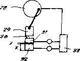
Fig. 9 utilizes piezoelectricity-performer to be placed in the wire stripping of tangent line or wire stripping position or the schematic diagram of tangential cutter;
Figure 10 adopts ultrasonic welding machine and measuring transducer to be used for the structural design of connecting line line end;
Figure 11 adopts the structural design of common pressure actuated device and the performer that adds;
Figure 12 adopts the common twin shaft that is used to drive with tightener sheave of additional performer to drive;
The flexible program of Figure 13 Figure 10 has a ultrasonic wave or electric resistance welding joint and performer, but does not have measuring transducer;
Figure 14 have the cutting of performer drive unit or clamp structure design and
Figure 15 adopt pair roller or bring into to the auxiliary structural design of toggle link.
In institute's drawings attached, represent identical parts, have the slightly different parts that the different identical Reference numerals of target down represent to have same function or similar effect simultaneously with identical Reference numeral.
The structure of four cutter 5a-d of the opening of the work openings A (for example cutting depth) that is in open work openings B and dwindles is shown respectively in Fig. 1 and 2.Cutter 5a-d of the present invention conforms to applicant's MP 8015 type cutters.Because principle of the present invention is applicable to clamping pincers or centering pincers too, so described cutter also can be regarded as clamp.
Described cutter 5 is fixed on respectively on the knife rest 4a-d that is attached troops to a unit, and described knife rest 4a-d can move and the big or small and cutting or the solid degree of depth of pincers of work openings A, B are adjusted along guide plate 3a-d respectively.
The performer 6a-d that utilizes a micromechanics of attaching troops to a unit respectively loads knife rest 4 and is performed device 6a-d path with knife rest 4 and accurately moves.The wire stripping head fixation side 8a-d of this micromechanics performer 6 is resisted against in the corresponding grooves of wire stripping head 1 for this reason, and another of performer 6a-d moves side 7a-d respectively to knife rest 4a-d loading and to closing direction feeding or retraction simultaneously.X represents to be in the length of the performer under the unstressed stress state, and Y represents length difference or feeding path simultaneously.Shown in the preferred performer of structural design be piezoelectricity-performer.
It can be in parallel maybe can controlling respectively that the voltage of the performer that schematically illustrates among the figure connects, and wherein loads with identical voltage simultaneously performer is preferred.Can or take the calibration measure to realize periodic calibration by mechanical compensation; But also can take the mode (by adjusting voltage difference) of electric calibration.
Certainly performer 6 also can be only as the auxiliary or micromatic setting to cutter 5 according to the present invention.In described structure, for example " the wire stripping head fixation side " 8 of performer 6 loaded by not shown common direct or indirect electromechanics or pneumatic actuating device, so that overcome long highway section (feeding highway section).
And can adopt mode such as unshowned lever transmission among Fig. 1 and 2, described lever transmission can further improve the efficient of performer.Scheme at a kind of lever drive mechanism shown in Fig. 3,4 and 15.Shown in Fig. 3,4, but the adjustment of operation opening A or B is not by the linearity adjustment to the cutter 11a-d of swing, but realize by the swing adjustment.Since the wire stripping type of action of this structure with conform in the disclosed structure of the applicant's EP-B-297484 or US-A-5010797 (Fig. 8 and Fig. 9 and relevant description part), so do not repeat them here.
In this swing cutter structure, cutter 11a-d is respectively around the fixing axle 10a-d swing of a cutterhead.Because cutter 11a-d is L shaped structure, thus will produce into the lever gearing, thus utilize very little Y-path, can be at cutting tool placket A, the last feeding path that produces abundance of B.Extension spring 12a-d is used to make cutter 11a-d to recover its initial position B again.Also can in the structure shown in Fig. 1 and 2, adopt similar spring.And cutter 11a-d or knife rest 4a-d can be fixedlyed connected with performer 6a-d, thereby under the situation that does not have additional elastic force, can realize the displacement of front and back by performer.
Punck-down block shown in Fig. 5,6 includes a cutting ray ingress pipe 19, makes a cutting ray 20 by this cutting ray ingress pipe, and for example a laser beam is projected onto on the reflector group 14.Be provided with a swing mirror 15 in reflector group 14 back, described swing mirror is controlled by performer 6i.The wire stripping head fixation side 8i of described performer 6i is fixed on on the wire stripping head 1c who is shown in dotted line, and it moves side 7e the swing lever 16 of swing mirror 15 is loaded, thereby cutting ray 20 is directed to, in alignment with a cable 9.The axis of wherein preferred misalignment cable 9, but aim at cable 9 sides (as shown in arrow 21).Adopt this structure can realize as shown in Figure 7 line of cut, the described line of cut side of heart yearn internally passes, thereby can not cause the damage to internal core.By around cable rotation wire stripping head 1c, thereby realize excision fully to separator by control accurately to swing mirror 15.
Structure shown in Figure 8 can be a rotational structure, but also can be non-rotating structure.Performer 6k-1 loads a cutter lever 23a-b respectively, and described cutter lever is placed in cutting position around a swing axle 24a-b respectively together with its cutter 5e-f.
The structure of Fig. 9 illustrates a performer 6m, and described performer roof pressure is on a compression spring 25 and be used for making cutter 5g to cut cable 9.Axle bed 38a, the b of fixed-site supports cable 9 on the one hand, on the other hand compression spring 25 supported.Axle bed 38a also can play a part a controllable bearing, thereby cable is relatively moved to cutter.Also can replace bearing 38a in addition, thereby can realize cutting from both sides to cable with adopting the structure identical with 6m.In addition also can or with combination with 38a as centring means, described centring means by spring 25 roof pressures on cable.Described structure also can rotatably be provided with around cable.
Performer 6n shown in the structure shown in Figure 10 and 13 and 6o, described performer loads a plumb joint 26a and 26b (for example ultrasonic bonding head or electric resistance welding joint), so that utilize plumb joint that the two ends 27a and the 27b of cable are welded together.According to the present invention, " welding " notion broadly contains " connection " for example " bonding " etc.According to the structure of Figure 10, also be provided with a measuring transducer 30 in addition, described measuring transducer monitors correct thrust and realizes control to thrust by the adjustment to the thrust of performer 6n in case of necessity.
Figure 11 illustrates a kind of crimping machine, wherein drive unit with the mode that moves back and forth with push rod 39 roof pressures on the scope of operation 39.Be provided with a measuring transducer 31 and the performer 32 as actuator below the scope of operation, described performer will promote the scope of operation when pressure is not enough, wherein upwards operation (Y) of performer 32.Measuring transducer 31 and performer 32 and drive unit 28 are controlled by negative feedback at a regulating loop 33.
Figure 12 is illustrated in the wire stripper (for example tangent line or wire stripper) voltage control to conveyer belt.Adopt known mode usually, the machine of Powerstrip 9500 types of producing with the applicant is identical, and described band is by left-hand thread bar 35 Be Controlled.Innovative point in this structure is, threaded rod 35 is separated in the centre, have a performer 6p in described centre, described performer carries out critically in opposite directions and opposing adjustment two threaded rod half parts, thereby can critically act on the cable between described band 34a, the b.
Figure 14 illustrates a kind of simple wire stripping pliers 36, and the jaw of described wire stripping pliers can load around axle 37 pivots and by a performer 6q.This figure also can relate to a kind of clamp, and wherein performer can be fixed-site (not shown to this) corresponding to axle also.
The strutting piece of toggle link shown in Figure 15 40 is supported on pair roller or can realizes bigger power on the one hand with 34 whens location by toggle link, can realize short path on the other hand.Roller is being directed on the guide rail 41 and can feeding and unlatching in centesimal scope when closure is mobile in this structure.
Also can adopt the 255-361 page or leaf of for example quoting from this manual that is entitled as " application of novel performer " book described as flexible program, particularly at the performer shown in Fig. 8 .1,8.3 and 13.9.
The Reference numeral table of comparisons
1 wire stripping head (rotation or irrotational) a, b, c
2 guide rail a-d
3 guide plate a-d
4 a-d
5 cutting tool a-g
6 micromechanics performer a-r
7 performers 6 move side a-e
The wire stripping head fixation side a-i of 8 performers 6
9 cables, line
10
But the cutter of 11 swings
12 extension springs
13 blades
14 fixing mirrors (mirror group)
15 swing mirrors
16 swing levers
17 swing arms
18 rotating shafts
The 19 cutting rays that can import (for example laser)
20 cutting rays (for example laser)
21 arrows
22 internal core wires
23 tool lever a-b
24 swing axle a-b
25 springs
26 plumb joint a-b
27 line ends
28 drive units
29 push rods
30 measuring transducers
31 transducers
32 actuators
33 regulating loops
34 conveyer belts
35 screw rods
36 wire stripping pliers
37
38 bearings
39 scope of operations
40 toggle links
41 guide rails
P for example utilizes centralizer with lead fixed point thereon
X does not apply the length of the performer under the proof stress situation
The length difference that the proof stress that Y applies causes
Claims (15)
1. device that cable, line are handled, drive unit (6) and/or the clamping device of cable (9) and/or the instrument that cable (9) is handled with at least one cable (9), and/or be used for being fixed on parts (plug) on the cable (9) and/or that be used at least two lines of connection (9,27) and/or being used to measure the instrument special characteristic of cable and/or that be used for the characteristic of mensuration process special use, it is characterized in that described drive unit comprises the performer (6) of a micromechanics at least.
2. according to the described processing unit of claim 1, it is characterized in that at least one drive unit comprises at least two performers that are serially connected (6).
3. according to claim 1 or 2 described processing unit, it is characterized in that drive unit comprises at least two performers identical or inequality at least one performer (6) or following group:
Ultrasonic wave-, bimetallic-, piezoelectricity-and/or progressive-worm screw engine; Monolithic multilayer-, electric charge control-, electrorheological-, hot flowage-and/or electrostriction or magnetostrictive performer; Parallel-the bimorph converter; Flexural piezoelectric device (bimorph); Piezoelectricity-mirror image transducer (for example in astronomical space telescope, using); Electrochemical, chemical machinery, electric heating static, (voltage expands or electric current expands) that hot gas is moving or dynamo-electric, the performer of microtechnic; The performer that memory material is made etc.
4. each described processing unit in requiring according to aforesaid right, it is characterized in that at least one drive unit comprises one by the drive unit (28,35) that is arbitrary common and that cooperate with the performer (6) of at least one micromechanics in following group: performer motor, electromagnetism, pneumatic or hydraulic pressure.。
5. each described processing unit in requiring according to aforesaid right is characterized in that drive unit (6) comprises at least one transducer (30), and described transducer preferably itself is made of the micromechanics performer.
6. each described device in requiring according to aforesaid right, it is characterized in that described micromechanics performer 6 acts on member to be adjusted by media such as a travelling gear and/or lever (40) and/or converter utilization a such as hydraulic oil, water, mercurys.
7. each described processing unit in requiring according to aforesaid right is characterized in that be provided with a control device, described control device is controlled on stretching, extension and shrinkage direction micromechanics performer (6), and wherein control device is preferably electric or electronics.
8. each described processing unit in requiring according to aforesaid right is characterized in that, described micromechanics performer (6) spring (25) that is reset loads.
9. each described processing unit in requiring according to aforesaid right is characterized in that, described micromechanics performer (6) is the controlling organization of the speculum (15) of cutter, centering pincers, roller, conveyer belt and jaw or laser (19,20).
10. each described processing unit in requiring according to aforesaid right is characterized in that, at least one micromechanics performer (6) be arranged on the cutter head of a rotation and and by a slip ring by feed.
11., it is characterized in that one has transducer (30 according to each described processing unit in the aforesaid right requirement; 31) regulating loop (33) is attached troops to a unit to described performer (6), and/or described performer (6) itself also can be used as transducer.
12. each described processing unit in requiring according to aforesaid right is characterized in that, for performer (6) can be provided with a control device (open loop) and an adjusting device (closed loop) is used to move, locatees and/or applies active force.
13. according to the described processing unit of claim 12, it is characterized in that, utilize one to be used to gather that performer (6) is gone up or the measuring unit of the actual measured value on a device of being adjusted by performer (6) or on cable (9) or line is realized control and/or regulate in working order down.
14. to the micromechanics performer, particularly to the application of piezo actuator spare, described micromechanics performer is used for the mechanical component of wire stripper is controlled, and realizes the location of these members corresponding to the cable that has stripped line to handle.
15. to the micromechanics performer, particularly to the application of piezo actuator spare, described micromechanics performer is used for the hydraulic pressure in the punck-down block or on the punck-down block, pneumatic, machinery or electro-mechanical driving device are carried out the Electronic Control error correction and improve precision.
Applications Claiming Priority (2)
| Application Number | Priority Date | Filing Date | Title |
|---|---|---|---|
| CH11292001 | 2001-06-15 | ||
| CH1129/2001 | 2001-06-15 |
Publications (1)
| Publication Number | Publication Date |
|---|---|
| CN1516913A true CN1516913A (en) | 2004-07-28 |
Family
ID=4559070
Family Applications (1)
| Application Number | Title | Priority Date | Filing Date |
|---|---|---|---|
| CNA028119517A Pending CN1516913A (en) | 2001-06-15 | 2002-06-17 | Processing device for cables or wires |
Country Status (5)
| Country | Link |
|---|---|
| US (1) | US20040134965A1 (en) |
| EP (1) | EP1402607A1 (en) |
| JP (1) | JP2004531191A (en) |
| CN (1) | CN1516913A (en) |
| WO (1) | WO2002103871A1 (en) |
Cited By (8)
| Publication number | Priority date | Publication date | Assignee | Title |
|---|---|---|---|---|
| CN100456576C (en) * | 2006-01-25 | 2009-01-28 | 矢崎总业株式会社 | Wire fixing device |
| CN103457138A (en) * | 2012-05-31 | 2013-12-18 | 深圳市大族激光科技股份有限公司 | Laser stripping device |
| CN103683125A (en) * | 2013-11-26 | 2014-03-26 | 深圳先进技术研究院 | Cable end sheath stripping method and device |
| CN102204046B (en) * | 2008-11-03 | 2015-09-16 | 施洛伊尼格控股有限公司 | Stripping machine is cut for what make cable section |
| CN105743026A (en) * | 2014-12-09 | 2016-07-06 | 大族激光科技产业集团股份有限公司 | Laser wire-stripping device |
| CN107332168A (en) * | 2017-09-04 | 2017-11-07 | 佛山伊贝尔科技有限公司 | A kind of automatic stripping machine and wire stripping equipment |
| CN109455579A (en) * | 2018-12-03 | 2019-03-12 | 王伟华 | A kind of communication network terminal cable storage device |
| CN112072626A (en) * | 2020-09-16 | 2020-12-11 | 亿嘉和科技股份有限公司 | Electrostatic protection circuit and wire stripper |
Families Citing this family (14)
| Publication number | Priority date | Publication date | Assignee | Title |
|---|---|---|---|---|
| US7013782B2 (en) * | 2000-08-16 | 2006-03-21 | Orbital Technologies, Inc. | Apparatus and method for cutting and stripping covering layers from a filamentary core including both rotary and reciprocating cutting blades |
| DE10357822A1 (en) * | 2003-12-09 | 2005-07-07 | Hesse & Knipps Gmbh | cutter |
| JP2005236103A (en) * | 2004-02-20 | 2005-09-02 | Shinkawa Ltd | Wire bonding apparatus |
| CN1992461B (en) * | 2005-12-30 | 2010-05-05 | 鸿富锦精密工业(深圳)有限公司 | Apparatus for cutting insulation layer of electric wire |
| JP2007189857A (en) * | 2006-01-16 | 2007-07-26 | Tanaka Seiki Kk | Stripping device of wire rod |
| JP4910546B2 (en) * | 2006-08-01 | 2012-04-04 | 住友電気工業株式会社 | Laser processing method for coaxial cable |
| US8850702B2 (en) * | 2009-05-26 | 2014-10-07 | Cardiac Pacemakers, Inc. | Cable consolidation with a laser |
| US8011557B1 (en) * | 2010-08-04 | 2011-09-06 | Cheng Uei Precision Industry Co., Ltd. | Automatic soldering machine |
| CH706510A2 (en) * | 2012-05-15 | 2013-11-15 | Huber+Suhner Ag | Method and device for producing an operative connection between a connector and a cable. |
| EP3068002B1 (en) * | 2015-03-12 | 2019-11-06 | Schleuniger Holding AG | Cable processing machine with improved precision mechanism for cable processing |
| US10109974B2 (en) * | 2016-01-29 | 2018-10-23 | The Boeing Company | Vibrating pallet system for automated wire insertion |
| JP6360118B2 (en) * | 2016-09-20 | 2018-07-18 | 本田技研工業株式会社 | Peeling device and peeling station |
| CN111934245B (en) * | 2020-08-07 | 2021-12-28 | 浙江机电职业技术学院 | Electric cutting device |
| CN118249167B (en) * | 2024-05-28 | 2024-08-27 | 国网山东省电力公司高青县供电公司 | Portable wiring device for electric power construction and use method thereof |
Family Cites Families (22)
| Publication number | Priority date | Publication date | Assignee | Title |
|---|---|---|---|---|
| US3909911A (en) * | 1973-04-30 | 1975-10-07 | Orthodyne Electronics | Method for removing insulating and shielding materials from flat conductors, circuits and components |
| JPS5426751A (en) * | 1977-08-01 | 1979-02-28 | Nippon Telegr & Teleph Corp <Ntt> | Cutting method and apparatus for optical fiber |
| DE2925070C2 (en) * | 1979-06-21 | 1982-05-06 | Siemens AG, 1000 Berlin und 8000 München | Device for separating several optical waveguides combined in one cable |
| US4377958A (en) * | 1981-04-02 | 1983-03-29 | The United States Of America As Represented By The Secretary Of The Department Of Health And Human Services | Remotely operated microtome |
| US4603803A (en) * | 1982-08-24 | 1986-08-05 | Asm Assembly Automation, Ltd. | Wire bonding apparatus |
| US4597522A (en) * | 1983-12-26 | 1986-07-01 | Kabushiki Kaisha Toshiba | Wire bonding method and device |
| GB8611399D0 (en) * | 1986-05-09 | 1986-06-18 | York Technology Ltd | Cleaving optical fibres |
| JPS63262634A (en) * | 1987-04-21 | 1988-10-28 | Minolta Camera Co Ltd | Bimorph driving system shutter device for camera |
| US5010797A (en) * | 1987-06-30 | 1991-04-30 | Jiri Stepan | Arrangement for cutting and/or stripping apparatuses |
| JP2601698B2 (en) * | 1988-08-30 | 1997-04-16 | 株式会社小松製作所 | Laser scanner rotation detection mechanism |
| JP2904817B2 (en) * | 1989-08-19 | 1999-06-14 | 株式会社日立製作所 | Cable termination equipment |
| JP2841126B2 (en) * | 1991-04-19 | 1998-12-24 | 株式会社新川 | Wire bonding method and apparatus |
| US5452838A (en) * | 1993-07-13 | 1995-09-26 | F & K Delvotec Bondtechnik Gmbh | Bonding head for an ultrasonic bonding machine |
| US5837961A (en) * | 1995-11-24 | 1998-11-17 | Miller; Richard T. | Laser wire stripping apparatus having multiple synchronous mirrors and a method therefor |
| JP3298783B2 (en) * | 1996-02-15 | 2002-07-08 | 株式会社新川 | Wire cut feeder for wire bonding equipment |
| US5788453A (en) * | 1996-05-30 | 1998-08-04 | Applied Materials, Inc. | Piezoelectric wafer gripping system for robot blades |
| DE19745468C1 (en) * | 1997-10-15 | 1999-04-15 | Daimler Chrysler Ag | Piezoelectric actuator |
| JP2997450B1 (en) * | 1998-07-17 | 2000-01-11 | 日特エンジニアリング株式会社 | Stripping device and coil for coil insulation coating |
| JP2000102132A (en) * | 1998-09-22 | 2000-04-07 | Yazaki Corp | Device and method for stripping middle part of insulated wire |
| DE19851353C1 (en) * | 1998-11-06 | 1999-10-07 | Schott Glas | Method and apparatus for cutting a laminate consisting of a brittle material and a plastic |
| US6225589B1 (en) * | 1999-03-15 | 2001-05-01 | Stephen Bartok | Electric discharge machining apparatus |
| JP3185208B2 (en) * | 1999-08-24 | 2001-07-09 | 住友電気工業株式会社 | Method of manufacturing a processed wire product, apparatus for manufacturing the same, and processed wire product |
-
2002
- 2002-06-17 US US10/480,749 patent/US20040134965A1/en not_active Abandoned
- 2002-06-17 WO PCT/IB2002/002250 patent/WO2002103871A1/en not_active Application Discontinuation
- 2002-06-17 EP EP02733161A patent/EP1402607A1/en not_active Withdrawn
- 2002-06-17 CN CNA028119517A patent/CN1516913A/en active Pending
- 2002-06-17 JP JP2003506071A patent/JP2004531191A/en active Pending
Cited By (11)
| Publication number | Priority date | Publication date | Assignee | Title |
|---|---|---|---|---|
| CN100456576C (en) * | 2006-01-25 | 2009-01-28 | 矢崎总业株式会社 | Wire fixing device |
| CN102204046B (en) * | 2008-11-03 | 2015-09-16 | 施洛伊尼格控股有限公司 | Stripping machine is cut for what make cable section |
| CN103457138A (en) * | 2012-05-31 | 2013-12-18 | 深圳市大族激光科技股份有限公司 | Laser stripping device |
| CN103457138B (en) * | 2012-05-31 | 2016-01-20 | 大族激光科技产业集团股份有限公司 | A kind of laser wire stripping device |
| CN103683125A (en) * | 2013-11-26 | 2014-03-26 | 深圳先进技术研究院 | Cable end sheath stripping method and device |
| CN103683125B (en) * | 2013-11-26 | 2016-09-21 | 深圳先进技术研究院 | Cable end sheath stripping means and device |
| CN105743026A (en) * | 2014-12-09 | 2016-07-06 | 大族激光科技产业集团股份有限公司 | Laser wire-stripping device |
| CN107332168A (en) * | 2017-09-04 | 2017-11-07 | 佛山伊贝尔科技有限公司 | A kind of automatic stripping machine and wire stripping equipment |
| CN109455579A (en) * | 2018-12-03 | 2019-03-12 | 王伟华 | A kind of communication network terminal cable storage device |
| CN109455579B (en) * | 2018-12-03 | 2020-07-03 | 绍兴市亚索新能源科技有限公司 | Communication network terminal cable line storage device |
| CN112072626A (en) * | 2020-09-16 | 2020-12-11 | 亿嘉和科技股份有限公司 | Electrostatic protection circuit and wire stripper |
Also Published As
| Publication number | Publication date |
|---|---|
| EP1402607A1 (en) | 2004-03-31 |
| US20040134965A1 (en) | 2004-07-15 |
| JP2004531191A (en) | 2004-10-07 |
| WO2002103871A1 (en) | 2002-12-27 |
Similar Documents
| Publication | Publication Date | Title |
|---|---|---|
| CN1516913A (en) | Processing device for cables or wires | |
| JP5878299B2 (en) | Ultrasonic vibration cutting device | |
| CN1047751C (en) | Method and device for cutting elastic material | |
| CN1582486A (en) | Semiconductor device and method for fabricating same | |
| CN1723543A (en) | Method of producing a complex structure by assembling stressed structures | |
| CN1181500C (en) | Wire products making method, equipment for making same and wire products | |
| CN1268053C (en) | Vibrating driver and shape estimating method of elastomer supporting member of its vibrator | |
| Abondance et al. | Piezoelectric grippers for mobile micromanipulation | |
| CN1596831A (en) | Ultrasonic probe and method for fabricating the probe | |
| CN1186825C (en) | Vibrating element and vibrating wave driving device | |
| CN1870413A (en) | Vibrational actuator and method for driving vibrational actuator | |
| CN1595783A (en) | Ultrasonic actuator driving apparatus and ultrasonic actuator driving method | |
| CN1080020C (en) | Method for treatment of end leadwire of stator coil for rotary electric motor, and apparatus thereof | |
| JP2016007660A (en) | Ultrasonic vibration cutting device | |
| US7727050B2 (en) | Vibrating device | |
| JP2006346769A (en) | Workpiece gripper | |
| CN1623240A (en) | Curved electro-active actuators | |
| US6196087B1 (en) | Apparatus and method for removing an insulation cover from an insulation covered wire at intermediate portion | |
| US11045897B2 (en) | Method and apparatus to form a workpiece employing vibration welding | |
| EP3144112A1 (en) | Gripper with indexable motor speed reducer | |
| CN112026332B (en) | Coating layer stripping equipment for processing stainless steel corrugated pipe for gas appliance | |
| CN1714286A (en) | Apparatus for simulating tensile forces on a workpiece | |
| JPH11118678A (en) | Method and apparatus for adjusting angle of microtome sample | |
| CN116536493B (en) | Small hole strengthening device and wire feeding guide hole machining method using same | |
| WO2013128579A1 (en) | Rotational cutting device and rotational cutting method |
Legal Events
| Date | Code | Title | Description |
|---|---|---|---|
| C06 | Publication | ||
| PB01 | Publication | ||
| C10 | Entry into substantive examination | ||
| SE01 | Entry into force of request for substantive examination | ||
| C02 | Deemed withdrawal of patent application after publication (patent law 2001) | ||
| WD01 | Invention patent application deemed withdrawn after publication |