CN1483111A - Cone selector and associated transmission assembly - Google Patents
Cone selector and associated transmission assembly Download PDFInfo
- Publication number
- CN1483111A CN1483111A CNA018212212A CN01821221A CN1483111A CN 1483111 A CN1483111 A CN 1483111A CN A018212212 A CNA018212212 A CN A018212212A CN 01821221 A CN01821221 A CN 01821221A CN 1483111 A CN1483111 A CN 1483111A
- Authority
- CN
- China
- Prior art keywords
- cone
- selector
- backing plate
- gear
- piston
- Prior art date
- Legal status (The legal status is an assumption and is not a legal conclusion. Google has not performed a legal analysis and makes no representation as to the accuracy of the status listed.)
- Granted
Links
Images


Classifications
-
- F—MECHANICAL ENGINEERING; LIGHTING; HEATING; WEAPONS; BLASTING
- F16—ENGINEERING ELEMENTS AND UNITS; GENERAL MEASURES FOR PRODUCING AND MAINTAINING EFFECTIVE FUNCTIONING OF MACHINES OR INSTALLATIONS; THERMAL INSULATION IN GENERAL
- F16D—COUPLINGS FOR TRANSMITTING ROTATION; CLUTCHES; BRAKES
- F16D21/00—Systems comprising a plurality of actuated clutches
- F16D21/02—Systems comprising a plurality of actuated clutches for interconnecting three or more shafts or other transmission members in different ways
- F16D21/04—Systems comprising a plurality of actuated clutches for interconnecting three or more shafts or other transmission members in different ways with a shaft carrying a number of rotatable transmission members, e.g. gears, each of which can be connected to the shaft by a clutching member or members between the shaft and the hub of the transmission member
-
- F—MECHANICAL ENGINEERING; LIGHTING; HEATING; WEAPONS; BLASTING
- F16—ENGINEERING ELEMENTS AND UNITS; GENERAL MEASURES FOR PRODUCING AND MAINTAINING EFFECTIVE FUNCTIONING OF MACHINES OR INSTALLATIONS; THERMAL INSULATION IN GENERAL
- F16D—COUPLINGS FOR TRANSMITTING ROTATION; CLUTCHES; BRAKES
- F16D13/00—Friction clutches
- F16D13/14—Friction clutches with outwardly-movable clutching members co-operating with the inner surface of a drum or the like
- F16D13/18—Friction clutches with outwardly-movable clutching members co-operating with the inner surface of a drum or the like shaped as linked or separately-pivoted segments
-
- F—MECHANICAL ENGINEERING; LIGHTING; HEATING; WEAPONS; BLASTING
- F16—ENGINEERING ELEMENTS AND UNITS; GENERAL MEASURES FOR PRODUCING AND MAINTAINING EFFECTIVE FUNCTIONING OF MACHINES OR INSTALLATIONS; THERMAL INSULATION IN GENERAL
- F16D—COUPLINGS FOR TRANSMITTING ROTATION; CLUTCHES; BRAKES
- F16D13/00—Friction clutches
- F16D13/22—Friction clutches with axially-movable clutching members
- F16D13/24—Friction clutches with axially-movable clutching members with conical friction surfaces cone clutches
- F16D13/32—Friction clutches with axially-movable clutching members with conical friction surfaces cone clutches in which two or more axially-movable members are pressed from one side towards an axially-located member
- F16D13/34—Friction clutches with axially-movable clutching members with conical friction surfaces cone clutches in which two or more axially-movable members are pressed from one side towards an axially-located member with means for increasing the effective force between the actuating sleeve or equivalent member and the pressure member
-
- F—MECHANICAL ENGINEERING; LIGHTING; HEATING; WEAPONS; BLASTING
- F16—ENGINEERING ELEMENTS AND UNITS; GENERAL MEASURES FOR PRODUCING AND MAINTAINING EFFECTIVE FUNCTIONING OF MACHINES OR INSTALLATIONS; THERMAL INSULATION IN GENERAL
- F16D—COUPLINGS FOR TRANSMITTING ROTATION; CLUTCHES; BRAKES
- F16D25/00—Fluid-actuated clutches
- F16D25/08—Fluid-actuated clutches with fluid-actuated member not rotating with a clutching member
- F16D25/082—Fluid-actuated clutches with fluid-actuated member not rotating with a clutching member the line of action of the fluid-actuated members co-inciding with the axis of rotation
-
- F—MECHANICAL ENGINEERING; LIGHTING; HEATING; WEAPONS; BLASTING
- F16—ENGINEERING ELEMENTS AND UNITS; GENERAL MEASURES FOR PRODUCING AND MAINTAINING EFFECTIVE FUNCTIONING OF MACHINES OR INSTALLATIONS; THERMAL INSULATION IN GENERAL
- F16H—GEARING
- F16H2200/00—Transmissions for multiple ratios
- F16H2200/003—Transmissions for multiple ratios characterised by the number of forward speeds
- F16H2200/0047—Transmissions for multiple ratios characterised by the number of forward speeds the gear ratios comprising five forward speeds
-
- F—MECHANICAL ENGINEERING; LIGHTING; HEATING; WEAPONS; BLASTING
- F16—ENGINEERING ELEMENTS AND UNITS; GENERAL MEASURES FOR PRODUCING AND MAINTAINING EFFECTIVE FUNCTIONING OF MACHINES OR INSTALLATIONS; THERMAL INSULATION IN GENERAL
- F16H—GEARING
- F16H3/00—Toothed gearings for conveying rotary motion with variable gear ratio or for reversing rotary motion
- F16H3/02—Toothed gearings for conveying rotary motion with variable gear ratio or for reversing rotary motion without gears having orbital motion
- F16H3/08—Toothed gearings for conveying rotary motion with variable gear ratio or for reversing rotary motion without gears having orbital motion exclusively or essentially with continuously meshing gears, that can be disengaged from their shafts
- F16H3/087—Toothed gearings for conveying rotary motion with variable gear ratio or for reversing rotary motion without gears having orbital motion exclusively or essentially with continuously meshing gears, that can be disengaged from their shafts characterised by the disposition of the gears
- F16H3/089—Toothed gearings for conveying rotary motion with variable gear ratio or for reversing rotary motion without gears having orbital motion exclusively or essentially with continuously meshing gears, that can be disengaged from their shafts characterised by the disposition of the gears all of the meshing gears being supported by a pair of parallel shafts, one being the input shaft and the other the output shaft, there being no countershaft involved
-
- Y—GENERAL TAGGING OF NEW TECHNOLOGICAL DEVELOPMENTS; GENERAL TAGGING OF CROSS-SECTIONAL TECHNOLOGIES SPANNING OVER SEVERAL SECTIONS OF THE IPC; TECHNICAL SUBJECTS COVERED BY FORMER USPC CROSS-REFERENCE ART COLLECTIONS [XRACs] AND DIGESTS
- Y10—TECHNICAL SUBJECTS COVERED BY FORMER USPC
- Y10T—TECHNICAL SUBJECTS COVERED BY FORMER US CLASSIFICATION
- Y10T74/00—Machine element or mechanism
- Y10T74/19—Gearing
- Y10T74/19219—Interchangeably locked
- Y10T74/19242—Combined gear and clutch
-
- Y—GENERAL TAGGING OF NEW TECHNOLOGICAL DEVELOPMENTS; GENERAL TAGGING OF CROSS-SECTIONAL TECHNOLOGIES SPANNING OVER SEVERAL SECTIONS OF THE IPC; TECHNICAL SUBJECTS COVERED BY FORMER USPC CROSS-REFERENCE ART COLLECTIONS [XRACs] AND DIGESTS
- Y10—TECHNICAL SUBJECTS COVERED BY FORMER USPC
- Y10T—TECHNICAL SUBJECTS COVERED BY FORMER US CLASSIFICATION
- Y10T74/00—Machine element or mechanism
- Y10T74/19—Gearing
- Y10T74/19219—Interchangeably locked
- Y10T74/19284—Meshing assisters
- Y10T74/19288—Double clutch and interposed transmission
-
- Y—GENERAL TAGGING OF NEW TECHNOLOGICAL DEVELOPMENTS; GENERAL TAGGING OF CROSS-SECTIONAL TECHNOLOGIES SPANNING OVER SEVERAL SECTIONS OF THE IPC; TECHNICAL SUBJECTS COVERED BY FORMER USPC CROSS-REFERENCE ART COLLECTIONS [XRACs] AND DIGESTS
- Y10—TECHNICAL SUBJECTS COVERED BY FORMER USPC
- Y10T—TECHNICAL SUBJECTS COVERED BY FORMER US CLASSIFICATION
- Y10T74/00—Machine element or mechanism
- Y10T74/19—Gearing
- Y10T74/19219—Interchangeably locked
- Y10T74/19293—Longitudinally slidable
- Y10T74/19335—Single spur gear
- Y10T74/1934—Tumbler and cone
- Y10T74/19344—Multiple cone
-
- Y—GENERAL TAGGING OF NEW TECHNOLOGICAL DEVELOPMENTS; GENERAL TAGGING OF CROSS-SECTIONAL TECHNOLOGIES SPANNING OVER SEVERAL SECTIONS OF THE IPC; TECHNICAL SUBJECTS COVERED BY FORMER USPC CROSS-REFERENCE ART COLLECTIONS [XRACs] AND DIGESTS
- Y10—TECHNICAL SUBJECTS COVERED BY FORMER USPC
- Y10T—TECHNICAL SUBJECTS COVERED BY FORMER US CLASSIFICATION
- Y10T74/00—Machine element or mechanism
- Y10T74/19—Gearing
- Y10T74/19219—Interchangeably locked
- Y10T74/19377—Slidable keys or clutches
- Y10T74/19386—Multiple clutch shafts
- Y10T74/19391—Progressive
-
- Y—GENERAL TAGGING OF NEW TECHNOLOGICAL DEVELOPMENTS; GENERAL TAGGING OF CROSS-SECTIONAL TECHNOLOGIES SPANNING OVER SEVERAL SECTIONS OF THE IPC; TECHNICAL SUBJECTS COVERED BY FORMER USPC CROSS-REFERENCE ART COLLECTIONS [XRACs] AND DIGESTS
- Y10—TECHNICAL SUBJECTS COVERED BY FORMER USPC
- Y10T—TECHNICAL SUBJECTS COVERED BY FORMER US CLASSIFICATION
- Y10T74/00—Machine element or mechanism
- Y10T74/19—Gearing
- Y10T74/19219—Interchangeably locked
- Y10T74/19377—Slidable keys or clutches
- Y10T74/19386—Multiple clutch shafts
- Y10T74/194—Selective
Landscapes
- Engineering & Computer Science (AREA)
- General Engineering & Computer Science (AREA)
- Mechanical Engineering (AREA)
- Hydraulic Clutches, Magnetic Clutches, Fluid Clutches, And Fluid Joints (AREA)
- Structure Of Transmissions (AREA)
- Gear-Shifting Mechanisms (AREA)
- Mechanical Operated Clutches (AREA)
- Friction Gearing (AREA)
Abstract
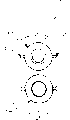
A multi cone selector in a transmission employs sandwiched cone friction surfaces 19A, 20A and 21A and these are shown in free or unengaged state while he corresponding friction surfaces as numerals 19, 20 and 21 are shown as engaged. This comparative illustration shows the relative positions of the surfaces at different times since the 'A' surfaces and the non 'A' surfaces are the same circumferential surfaces. The cone selector is used to engage free rotating gear a female part 22 of a multi-cone selector. A hydraulic actuator 23 is received by internal gear case wall 24 formed so as to prevent any radial or axial movement of the actuator itself. A hydraulic coupling, in this case the hydraulic coupling is formed as hydraulic springs or bags illustrated at 26. The crown of hydraulic spring outlet piston is formed so as to clip in a housing of a thrust bearing 29. The function of thrust bearing 29 is to provide relative rotational movements between cone clutch male part 30 and a piston of a hydraulic spring whether in idling or power transmitting mode. Twin cone selector comprises male part 30, female part 22 and cones 31 and 32. Cone 31 operates as a driving cone and is constrained but free to slide parallel to the axis of rotation 28 in circular slots 33. Cone 32 operates as a driven cone and is constrained but free to slide parallel to the axis of rotation in circular slots 36.
Description
Invention field
The present invention relates to cone selector and relevant transmitting assemblies, relate in particular to but be not limited to use the small-sized transmitting assemblies of two rotating shafts.
Background of invention
The applicant's U. S. Patent 6,092,432 and International Patent Application WO 00/71909 by reference as reference, the fixed engagement transmission device of description is used the mekydro selector and is meshed free transmitting gear in first rotating shaft, transmits driving force with the fixed gear on adjacent shafts.The present invention relates to exploitation and be fit to, 432 and the universal structure that disclosed of WO 00/71909 is described and the gear selector of the transmission type of control by U. S. Patent 6,092.
Summary of the invention
One aspect of the present invention is a kind of cone selector of selecting gear in transmission device, this cone selector has been used the female cone face and has been had and driven the conical surface and the male cone (strobilus masculinus) body that drives the conical surface, being driven the conical surface is driving between the conical surface and the female cone face, the male cone (strobilus masculinus) body utilizes the male cone (strobilus masculinus) body drive to move axially, and makes the engagement of the described conical surface and selects this gear.The male cone (strobilus masculinus) body drive comprises a hydraulic transmission assembly, and it contains the hydraulic coupling of input piston, output piston and these two piston spaces.Hydraulic coupling preferably is configured to amplification power.The hydraulic pressure cylinder assembly of described male cone (strobilus masculinus) body drive is preferably a kind of stationary annular cylinder component, uses thrust bearing output piston is connected to the male cone (strobilus masculinus) body." many conical surfaces " refers to use the conical surface that driven that is clipped between other conical surface.
Preferably, increase and driven conical surface number between the positive female cone face, can increase surface area.
In a preferred versions, positive female cone body is a fan body cone of gears body structure part.
Preferably, cone quilt guide rail separately is forced to move axially.Guide rail is generally the guide rail of concentric, axial slip separately, moves to extend axially aiming means.
Another aspect of the present invention is a kind of transmitting assemblies that input, output and permanent engagement gear are arranged, be used for selecting predetermined input and output ratio selectively input to be connected to output by gear, at least one described gear is free transmitting gear, the base gear selector comprises to be used the female cone face and is with the male cone (strobilus masculinus) body that is driven the conical surface and drive the conical surface, being driven the conical surface is driving between the conical surface and the female cone face, the male cone (strobilus masculinus) body can move axially by the male cone (strobilus masculinus) body drive, makes described conical surface engagement.
Preferably, this transmission device is a fixed engagement transmission device, and all gears have wherein been used the many conical surfaces selector that mixes, first and more against the conical surface of gear, and the conical surface of other gear is less.
In another embodiment, the main many conical surfaces selector group of driving on the axle of transmission device application makes and passes actively normally.
In a preferred versions, transmission device comprises that another at least contains the gear selector of bulging selector, the drum selector is used the isolated pad of plurality of peripheral, each pad has a peripheral pad face that extends, the pad drive unit drives pad and drum face driving engagement, the bulging face of common free transmitting gear assembly, gear assembly has a gear, when the described bulging face of described pad face engagement under the influence of described drive unit, can mesh, pad forwards not engaging position of bulging face to around first pivot, and forwards bulging face engaging position to around second pivot of opening with first pivotal interval.
Preferably, generally rotate freely gear assembly comprise one with the gear of fixed gear permanent engagement.Preferably, every pad supports that by the pad carrier for shifting described pad onto bulging face not engaging position under centrifugal forces affect, the center of gravity and the pivot of carrier separate.Preferably, the pad carrier has first end and second end on the other side of close center of gravity, and biased member is pressed to described drive unit with described second end, and described pad is remained on not engaging position of bulging face, up to being overcome by described biased member.
The pad drive unit is preferably a kind of annular hydraulic pressure cylinder assembly, and having can axially movable input piston, the middle hydraulic coupling of the output piston that can move radially and piston space.Preferably, output piston can enclose outside under described biased member influence and do peripheral moving between the position spaced.The hydraulic pressure cylinder assembly of drive unit is preferably a kind of stationary annular cylinder component, is used for thrust bearing output piston is attached to the male cone (strobilus masculinus) body.
Brief description
Fig. 1 is the general view of transmission device five fast double-shaft mechanisms.
Fig. 2 is the cross section by B-B line among Fig. 1.
Fig. 3 is the amplification end view of the double-cone clutch of manipulation first gear shown in Figure 1.
Fig. 4 is the sectional view of A-A line among Fig. 3, and double-cone clutch shown in Figure 1, hydraulic spring grease cup and hydraulic actuator mechanism are shown.
Fig. 5 is an amplification end view, illustrates by the drum of Fig. 1 and the hydraulic spring grease cup and the electric solenoid actuator of bipyramid face gear selector.
Fig. 6 is a C-C line sectional view among Fig. 5, and the hydraulic spring grease cup and the electric actuator mechanism of cone clutch operation is shown.
Fig. 7 is the amplification end view by the drum type clutch of Fig. 1 and second, third, the 4th and the 5th gear coupling.
Fig. 8 is a D-D line sectional view among Fig. 7, and the hydraulic spring grease cup and the hydraulic actuator mechanism of operating bulging clutch by Fig. 1 are shown.
Fig. 9 is the partial enlarged view of Fig. 7, and the detailed geometric figure of driving element and hydraulic spring grease cup is shown.
Figure 10 and 11 illustrates the bipyramid face of above-mentioned accompanying drawing shown type by comparative examples in Figure 11 bottom, and by relatively illustrating on Figure 11 top, is driven conical surface number by increasing between the positive female cone face, has increased surface area.
Figure 12 illustrates the present invention another embodiment to many cones selector of all gear application mix in five fast transmission devices, the cone selector be used for first with anti-gear, the bicone selector can be used for aforesaid other gear substantially.
Embodiment
With reference to Fig. 1, illustrated transmission device 10 comprises by the gear back-and-forth method that will describe rotating shaft, freedom and the fixed gear of input with the output joint operation.This transmission device belongs to and relates to free transmitting gear and be equipped with the type that gear is selected assembly, and each a free transmitting gear and a fixed gear keep constant engagement.Among Fig. 1, on each fixed gear that the constant engagement of combination is freely rotated and fixed gear is right, selection first to the 5th and reverse required gear are designated as 1-5 and R.Rotating shaft 11 and 11A be bearing in bearing 12A, 13 and 13B on; Rotating shaft 14 is bearing on bearing 12,13A and the 13C with 14A.Rotating shaft 11 and 11A, 14 and 14A connect the jail at their junction points separately with tooth bar.First gear (1) is individually fixed in input rotating shaft 11A and 11 with contrary gear (R).By the general structure of transmission device shown in Figure 1, all free gear 1A-RA rotate and attach to bicone or drum selector on sliding bearing.Typical case's bicone selector profile is shown in cross section 15, and its detail drawing is shown in Fig. 3 and 4.Typical case's drum selector is shown in cross section 16, and its detail drawing is shown in Fig. 7,8 and 9.
Fig. 2 illustrates annular oil hydraulic cylinder 17 and 18 and keep the gearbox flange fitting seat 19 of oil hydraulic cylinder.Add hydraulic pressure by the 20 pairs of fluid cylinders that enter the mouth, and the air per os 21 that picture obtains is discharged.Oil hydraulic cylinder 18 is provided with corresponding ports.Cylinder 17 is selected gear 1, and cylinder 18 is selected gear 3.Each gear mesh has its oneself annular oil hydraulic cylinder.
Fig. 3 and 4 illustrates the typical bicone selector enlarged detailed that can be used as gear 1 selector.The diagram selector generally is applicable to the selector of any gear.The bicone selector rises to three times that single cone generates to the merit of transmission and moment, and this is by increasing to three pairs of realizations to the friction surface number by a pair of.With reference to Fig. 4 top, friction surface is numbered 19A, 20A and 21A, and is shown freedom or does not engage attitude, and Fig. 4 bottom illustrates the corresponding friction surface that label 19,20 engages with 21.Obviously, this only is a kind of comparative example, and in practical operation, these friction surfaces only are in one of shown position at any one time, because " A " surface is same circumferential surface with non-" A " surface.As can be seen, merit and moment pass to from gear 1 input shaft and are driven axle 14 and realize by following path:
When the oil hydraulic cylinder 23 to Fig. 4 adds hydraulic fluid pressure, just piston 25 is produced axial force.This masterpiece is used for hydraulic coupling spring 26 and withstands elastic hose 27, makes the male cone (strobilus masculinus) body 30 in the groove 38 along axle 39 precession cone 31 and 32 be clamped female cone body 22.Another volute spring 40 between positive female cone body, when cutting off hydraulic pressure, it retracts to male cone (strobilus masculinus) and freely rotates attitude.When cutting off hydraulic pressure, the pressure spring 36 shown in Fig. 3 and 4 and 37 will drive cone 31 and be driven cone 32 and retract to and freely rotate attitude.Distance among Fig. 4 " X " indication male cone (strobilus masculinus) body is bonded into the total displacement of throwing off selector.Chock 34 and 35 gaps with respect to cone 31 and 32 be " X " 2/3.In middle condition or when not engaging attitude, uniform gap is arranged between cone like this.
Fig. 5 and 6 illustrates another embodiment, and same label is represented same parts, relate to electric solenoid 41 with 42 and hydraulic spring grease cup joiner 43 drive the bicone selector.When solenoid was energized, the annular plunger 44 that driven by magnetomotive force was pushed down male cone (strobilus masculinus) body 30 to hydraulic spring grease cup 43 and piston thereof, and the cone selector is engaged.The cone of segment angle shown in the figure 22, but omitted many male cone (strobilus masculinus) bodies 31 and 32.Fig. 5 and 6 only illustrates another kind of transmission.
In this preferred embodiment, as shown in Figure 1, the bicone selector be applicable to first with contrary gear.In this general structure, other gear drive is handled by the bulging selector that driven by hydraulic pressure cylinder assembly and difformity hydraulic spring grease cup, but principle function as mentioned above.
With reference to Fig. 7 and 8, as can be seen, typically rousing selector 9 has contact, a friction district between driving backing plate 45 and drum 46.Hydraulic spring grease cup body 47 is as the joiner between input and output piston 48 and 49.Hydraulic spring grease cup increases several times to the pressure that drives backing plate 45, thereby the oil hydraulic pump pressure of available attenuating transmits higher power and moment.On this meaning, hydraulic coupling works to put forth effort multiplier or amplifier.
Hydraulic spring grease cup comprises body 47, output piston 49, input piston 48 and spring bag 50.Bag 50 is by forming with the elastic material and the hydraulic fluid of transmission device compatibility, and the inside is filled with the fluid with hydraulic characteristic and become colloid, and hermetically sealed leakproof.Spring bag 50 be shaped will with piston 49 and 48 and the cavity precision-fit that limits of spring body 47, thereby when it is pressurizeed by piston 48, provide constant compression force by 49 pairs of backing plates 45 of output piston, and axial motion converted to radial motion.The power that output piston 49 produces is the function of the power sent of the throw-out collar 51 of the sectional area of its sectional area and input piston 48 and 52 settings of annular oil hydraulic cylinder.
As seen from Figure 9, the drum gear selector 9 that application of aforementioned drives the backing plate geometrical shape allows backing plate contact fully with drum, and the hydraulic spring grease cup joiner that comprises makes this assembly simply and effectively solve the power branch problem of gear.Elongated frame axle 53 is by measuring by " H1 " in the horizontal direction, measure perforate in Vertical direction by " V1 ", practicable contact fully.It is own by doing byer force in the zone that requires to drive backing plate 45, has also improved intensity.The center of gravity Cg of every backing plate makes the centrifugal force Cf of backing plate act on direction shown in Figure 9 in pivoting point 53 left sides, thereby backing plate keeps not contacting with bulging when rotating with middle condition.One end hook of spring 54 is gone into the groove 55 of backing plate 45, and the other end is fixed in a little 56, also rests on the hydraulic spring grease cup at point 52.Spring structure has and shape allows spring 54 to act on two main directions that backing plate 45 proper functioning are required.An effect is to make a P1 move into some P2 by make backing plate 45 change distance " H1, V1 " around pivot 53, moves backing plate 45 to neutral position 45A around its pivoting point 53.When moving backing plate 45 to position 45A, hydraulic spring grease cup 47 just forwards position 47A to and withstands spring 54 around its pivoting point 51 simultaneously.These two kinds of moving handle backing plates 45 place its resting guard, form clearance G 1 and G2 respectively at the backing plate back side and front.Must point out that when gear was in free mode of operation, centrifugal force Cf was the main power that backing plate is remained on neutral position.This result of differential pivot P1, P2 has improved backing plate 45 and has contacted with the surface of 46 of drums.
This example has illustrated the use of bicone friction selector and drum friction selector, and the hydraulic spring grease cup of the two adapted is all as the device of selection and engaging gear.
Except can changing by designing requirement application choice device, some gear is also used bigger clutch surfaces, uses the extra cone of being driven as first gear and comparable other gear of contrary gear.Figure 10 and 11 comparative view show this situation.Should be appreciated that, Figure 11 is individual drawing, but in fact two kinds of different selectors are shown, a kind of application fan body conical clutch 100, the another kind of bicone clutch 101 of using, the fan body conical clutch has increased the surface area that is suitable for than low gear, and the bicone clutch is fit to use the higher gear of same fundamental section, so use all many cone clutch rather than rouse the assembly that friction clutch can be made compactness.The transmission device 102 of Figure 12 is examples, embodiment with Fig. 1 is same common form in itself, because transmission is constant engagement driving, just all used cone clutch type selector this moment, fan body conical clutch type selector is used for first and contrary gear 103 and 104, and bicone clutch-type selector is used for other gear.
Figure 13 illustrates the another kind of applied in any combination of many conical clutchs type selector and transmission device, use this moment the selector that input shaft 106 is used fan body conical clutch 105 to replace common torque converter, illustrated clutch 105 is in flywheel 107, obviously can use this many conical clutchs structure in transmitting assemblies, should use torque converter this moment in the assembly outside.
Therefore, obviously can do multiple correction and improvement and without prejudice to broad range of the present invention that appended claim proposed to above illustrational transmission General Construction system and gear selector.
Claims (30)
1. in transmission device, select the described cone selector of gear for one kind, it is characterized in that, described cone selector is used a female cone face and is had and driven the conical surface and the male cone (strobilus masculinus) body that drives the conical surface, being driven the conical surface is driving between the conical surface and the female cone face, the male cone (strobilus masculinus) body can move axially by the male cone (strobilus masculinus) body drive the described conical surface is engaged, thereby selects this gear.
2. cone selector as claimed in claim 1 is characterized in that, the male cone (strobilus masculinus) body drive comprises a hydraulic driving assembly, and described assembly comprises the hydraulic coupling between input piston, output piston and input and the output piston.
3. cone selector as claimed in claim 1, it is characterized in that, the male cone (strobilus masculinus) body drive comprises a hydraulic driving assembly, and described assembly comprises the hydraulic coupling between input piston, output piston and input and the output piston, and hydraulic coupling comprises the power amplifier.
4. cone selector as claimed in claim 1, it is characterized in that, the male cone (strobilus masculinus) body drive comprises a hydraulic driving assembly, described assembly comprises the hydraulic coupling between input piston, output piston and input and the output piston, the hydraulic pressure cylinder assembly of described male cone (strobilus masculinus) body drive is a fixing annular cylinder component, has the thrust bearing that output piston is connected to the male cone (strobilus masculinus) body.
5. cone selector as claimed in claim 1 is characterized in that, positive female cone body all is a part of using " many conical surfaces " structure that is clipped in the conical surface between other conical surface.
6. cone selector as claimed in claim 1 is characterized in that, positive female cone body all is the part of fan-shaped cone structure.
7. cone selector as claimed in claim 1 is characterized in that, cone is limited to by separately guide rail and moves axially.
8. cone selector as claimed in claim 1 is characterized in that, cone by separately vertically the concentric, axial slide rail that moves of extensible track be limited to and move axially.
9. cone selector as claimed in claim 1, it is characterized in that, the male cone (strobilus masculinus) body drive comprises a hydraulic driving assembly, described assembly comprises the hydraulic coupling between input piston, output piston and input and the output piston, and positive female cone body all is a part of using " many conical surfaces " structure that is clipped in the conical surface between other conical surface.
10. cone selector as claimed in claim 1, it is characterized in that, the male cone (strobilus masculinus) body drive comprises a hydraulic driving assembly, described assembly comprises the hydraulic coupling between input piston, output piston and input and the output piston, hydraulic coupling comprises the power amplifier, and positive female cone body all is a part of using " many conical surfaces " structure that is clipped in the conical surface between other conical surface.
11. cone selector as claimed in claim 1, it is characterized in that, the male cone (strobilus masculinus) body drive comprises the hydraulic driving assembly, described assembly comprises the hydraulic coupling between input piston, output piston and input and the output piston, hydraulic coupling comprises the power amplifier, and cone is limited to and moves axially to extend axially concentric, axial slide rail that the rail mode moves separately.
12. transmitting assemblies, it is characterized in that, its input, output and all gears often mesh by the gear back-and-forth method and than selectively input are connected to output with predetermined input and output, at least one described gear be a kind of have gear selector and have driven the conical surface and the free transmitting gear that drives the conical surface, described gear selector comprises a female cone face and a male cone (strobilus masculinus) body, driven the conical surface and driving between the conical surface and the female cone face, the male cone (strobilus masculinus) body moves axially by the male cone (strobilus masculinus) body drive and the described conical surface is engaged.
13. transmitting assemblies as claimed in claim 12, it is characterized in that, transmission be a kind of have first with the constant engagement transmission of contrary gear and a series of other gears, described transmission is to many cones selector of all the gear application mix in the transmission, selector has higher conical surface number to first with contrary gear, and selector has lower conical surface number to other gear.
14. transmitting assemblies as claimed in claim 12 is characterized in that, described transmitting assemblies has a main drive shaft to described input, also comprises the many cones selector assembly that is used to control to the input transmission on main drive shaft.
15. transmitting assemblies as claimed in claim 12, it is characterized in that, transmitting assemblies comprises another gear selector at least, this selector comprises the bulging selector of using peripheral spacing plate, each backing plate has a peripheral backing plate surface of extending, the backing plate transmission device is driven into backing plate with the transmission of drum face and engages, the drum face connects normal free transmitting gear assembly, when described backing plate surface engages described bulging face under the influence of described transmission device, a gear of gear assembly can engage, backing plate forwards the asynthetic position of bulging face to around first pivotal axis, and around forwarding the position that bulging face engages to second pivotal axis that first pivotal axis separates.
16. transmitting assemblies as claimed in claim 12 is characterized in that, free transmitting gear assembly comprises a gear with the fixed gear permanent engagement.
17. transmitting assemblies as claimed in claim 12, it is characterized in that, transmitting assemblies comprises another gear selector at least, this selector comprises the bulging selector of using peripheral spacing plate, each backing plate has a peripheral backing plate surface of extending, the backing plate transmission device is driven into backing plate with the transmission of drum face and engages, the drum face connects normal free transmitting gear assembly, when described backing plate surface engages described bulging face under the influence of described transmission device, a gear of gear assembly can engage, backing plate forwards the asynthetic position of bulging face to around first pivotal axis, and around forwarding the position that bulging face engages to second pivotal axis that first pivotal axis separates, the backing plate carrier supporting that each backing plate is separated by center of gravity and pivotal axis is to shift described backing plate onto the asynthetic position of bulging face under centrifugal action.
18. transmitting assemblies as claimed in claim 12, it is characterized in that, transmitting assemblies comprises another gear selector at least, this selector comprises the bulging selector of using peripheral spacing plate, each backing plate has a peripheral backing plate surface of extending, the backing plate transmission device is driven into backing plate with the transmission of drum face and engages, the drum face connects normal free transmitting gear assembly, when described backing plate surface engages described bulging face under the influence of described transmission device, a gear of gear assembly can engage, backing plate forwards the asynthetic position of bulging face to around first pivotal axis, and around forwarding the position that bulging face engages to second pivotal axis that first pivotal axis separates, the backing plate carrier supporting that each backing plate is separated by center of gravity and pivotal axis, under centrifugal action, described backing plate shifted onto the asynthetic position of bulging face, first end of backing plate carrier is more near center of gravity, second end is relative with described first end, and biased member is pressed to described transmission device to described second end, described backing plate is remained on bulging face unengaged position, up to being overcome by described biased member.
19. transmitting assemblies as claimed in claim 12, it is characterized in that, transmitting assemblies comprises another gear selector at least, this selector comprises the bulging selector of using peripheral spacing plate, each backing plate has a peripheral backing plate surface of extending, the backing plate transmission device is driven into backing plate with the transmission of drum face and engages, the drum face connects normal free transmitting gear assembly, when described backing plate surface engages described bulging face under the influence of described transmission device, a gear of gear assembly can engage, the backing plate transmission device comprises an annular hydraulic pressure cylinder assembly, and it has can axially movable input piston, middle hydraulic coupling between output piston that can move radially and the two-piston.
20. transmitting assemblies as claimed in claim 12, it is characterized in that, transmitting assemblies comprises another gear selector at least, this selector comprises the bulging selector of using peripheral spacing plate, each backing plate has a peripheral backing plate surface of extending, the backing plate transmission device is driven into backing plate with the transmission of drum face and engages, the drum face connects normal free transmitting gear assembly, when described backing plate surface engages described bulging face under the influence of described transmission device, a gear of gear assembly can engage, the backing plate transmission device comprises an annular hydraulic pressure cylinder assembly, it has can axially movable input piston, middle hydraulic coupling between output piston that can move radially and the two-piston, under described biased member influence, output piston can be done peripheral moving between position at interval, periphery, the hydraulic pressure cylinder assembly of transmission device is preferably a kind of fixing annular cylinder component, is furnished with the thrust bearing that output piston is connected to the male cone (strobilus masculinus) body.
21. transmitting assemblies as claimed in claim 12 is characterized in that, male cone (strobilus masculinus) body transmission device comprises a hydraulic transmission assembly, and it comprises the hydraulic coupling between input piston, output piston and input and the output piston.
22. transmitting assemblies as claimed in claim 12 is characterized in that, male cone (strobilus masculinus) body transmission device comprises a hydraulic transmission assembly, and it comprises the hydraulic coupling between input piston, output piston and input and the output piston, and hydraulic coupling comprises the power amplifier.
23. transmitting assemblies as claimed in claim 12, it is characterized in that, male cone (strobilus masculinus) body transmission device comprises hydraulic transmission assembly, it comprises the hydraulic coupling between input piston, output piston and input and the output piston, the hydraulic pressure cylinder assembly of described male cone (strobilus masculinus) body transmission device is a kind of fixing annular cylinder component, is furnished with the cone bearing that ends that output piston is connected to the male cone (strobilus masculinus) body.
24. transmitting assemblies as claimed in claim 12 is characterized in that, positive female cone body all is a part of using " many conical surfaces " structure that is clipped in the conical surface between other conical surface.
25. transmitting assemblies as claimed in claim 12 is characterized in that, positive female cone body all is the part of fan body cone structure.
26. transmitting assemblies as claimed in claim 12 is characterized in that, cone is moved axially by guide rail restriction separately.
27. transmitting assemblies as claimed in claim 12 is characterized in that, cone is limited to and is moved axially to extend axially concentric, axial slide rail that the guide rail mode moves separately.
28. transmitting assemblies as claimed in claim 12, it is characterized in that, male cone (strobilus masculinus) body transmission device comprises hydraulic transmission assembly, it comprises the hydraulic coupling between input piston, output piston and input and the output piston, and positive female cone body all is a part of using " many conical surfaces " structure that is clipped in the conical surface between other conical surface.
29. transmitting assemblies as claimed in claim 12, it is characterized in that, the male cone (strobilus masculinus) body drive comprises hydraulic transmission assembly, the latter comprises the hydraulic coupling between input piston, output piston and input and the output piston, hydraulic coupling comprises the power amplifier, and positive key cone all is to use the part of " many conical surfaces " structure that is clipped in the conical surface between other conical surface.
30. transmitting assemblies as claimed in claim 12, it is characterized in that, the male cone (strobilus masculinus) body drive comprises hydraulic transmission assembly, the latter comprises the hydraulic coupling between input piston, output piston and input and the output piston, hydraulic coupling comprises the power amplifier, and cone is constrained to and moves axially to extend axially concentric, axial slide rail that the guide rail mode moves separately.
Applications Claiming Priority (5)
| Application Number | Priority Date | Filing Date | Title |
|---|---|---|---|
| AUPR1232A AUPR123200A0 (en) | 2000-11-03 | 2000-11-03 | Cone clutch and associated transmission assembly |
| AUPR1232 | 2000-11-03 | ||
| AUPR2557A AUPR255701A0 (en) | 2001-01-16 | 2001-01-16 | Cone clutch and associated transmission assembly |
| AUPR2557 | 2001-01-16 | ||
| PCT/AU2001/001416 WO2002036977A1 (en) | 2000-11-03 | 2001-11-02 | Cone selector and associated transmission assembly |
Publications (2)
| Publication Number | Publication Date |
|---|---|
| CN1483111A true CN1483111A (en) | 2004-03-17 |
| CN100350165C CN100350165C (en) | 2007-11-21 |
Family
ID=25646497
Family Applications (1)
| Application Number | Title | Priority Date | Filing Date |
|---|---|---|---|
| CNB018212212A Expired - Fee Related CN100350165C (en) | 2000-11-03 | 2001-11-02 | Cone selector and associated transmission assembly |
Country Status (8)
| Country | Link |
|---|---|
| US (2) | US7231845B2 (en) |
| EP (1) | EP1330614A4 (en) |
| JP (2) | JP4436603B2 (en) |
| CN (1) | CN100350165C (en) |
| AR (1) | AR031208A1 (en) |
| AU (1) | AU1366702A (en) |
| MY (1) | MY131406A (en) |
| WO (1) | WO2002036977A1 (en) |
Cited By (5)
| Publication number | Priority date | Publication date | Assignee | Title |
|---|---|---|---|---|
| CN102301156A (en) * | 2009-05-19 | 2011-12-28 | Ut全球有限公司 | Multistage automatic transmission |
| CN104114891A (en) * | 2011-12-17 | 2014-10-22 | Fte汽车股份有限公司 | Central release unit for a hydraulic clutch actuation means |
| CN104942654A (en) * | 2015-06-25 | 2015-09-30 | 苏州绿的谐波传动科技有限公司 | Separated conical surface connecting device |
| CN107448494A (en) * | 2017-09-22 | 2017-12-08 | 芜湖禾丰离合器有限公司 | A kind of clutch provided with limited block |
| WO2023000138A1 (en) * | 2021-07-19 | 2023-01-26 | 宁波吉利罗佑发动机零部件有限公司 | Cone clutch and transmission |
Families Citing this family (8)
| Publication number | Priority date | Publication date | Assignee | Title |
|---|---|---|---|---|
| AUPR123300A0 (en) * | 2000-11-03 | 2000-11-30 | Select Design Technologies Limited | Hydraulic gear selection drive means and associated transmission assembly |
| GB2387882A (en) * | 2002-02-08 | 2003-10-29 | Tim Payne Overdrive Designs Lt | A compact hydraulic actuator for an epicyclic gearbox |
| AU2003902820A0 (en) * | 2003-06-05 | 2003-06-26 | Select Design Technologies Limited | Drive coupliers |
| CA2657637C (en) * | 2008-03-31 | 2016-09-20 | Magna Powertrain Usa, Inc. | Electric dual input clutch transmission |
| US8943917B2 (en) * | 2010-10-20 | 2015-02-03 | Gm Global Technology Operations, Llc | Manual transmission |
| KR101601472B1 (en) * | 2014-08-22 | 2016-03-09 | 현대자동차주식회사 | Transmission for electric vehicle |
| US9989056B2 (en) | 2014-09-22 | 2018-06-05 | Concentric Rockford Inc. | Hydraulic pump with integrated clutch |
| EP3104032A3 (en) | 2015-05-29 | 2017-01-25 | Rolls-Royce North American Technologies, Inc. | Clutch with redundant engagement systems |
Family Cites Families (34)
| Publication number | Priority date | Publication date | Assignee | Title |
|---|---|---|---|---|
| US609432A (en) | 1898-08-23 | Vaginal syringe | ||
| US1300896A (en) * | 1917-11-06 | 1919-04-15 | Thomas Lucien Taliaferro | Jar-closure. |
| US1300898A (en) * | 1918-06-08 | 1919-04-15 | Patrick Henry Hays | Fluid-pressure clutch. |
| US2283292A (en) * | 1941-03-20 | 1942-05-19 | Ingersoll Rand Co | Percussive tool |
| US2510469A (en) * | 1945-01-11 | 1950-06-06 | Studebaker Corp | Transmission |
| US2965205A (en) * | 1957-09-23 | 1960-12-20 | Gen Motors Corp | Transmission |
| DE1239145B (en) * | 1959-05-29 | 1967-04-20 | Karl Obermoser Dr Ing | Friction clutch or brake |
| US3286801A (en) * | 1964-07-17 | 1966-11-22 | Dana Corp | Synchronizing clutch with multiple conical discs |
| US3338350A (en) * | 1965-04-28 | 1967-08-29 | Horton Mfg Co Inc | Frictional torque transmitting device |
| US3835974A (en) * | 1973-01-05 | 1974-09-17 | Excelermatic | Internal clutch |
| US4099601A (en) * | 1976-10-08 | 1978-07-11 | Telex Computer Products, Inc. | Solenoid operated cone brake |
| JPS54145840A (en) * | 1978-04-27 | 1979-11-14 | Honda Motor Co Ltd | Hydraulically operating clutch |
| US4226318A (en) * | 1978-10-10 | 1980-10-07 | Lambert Brake Corporation | Hydraulically actuated cone clutch |
| US4368650A (en) * | 1979-11-05 | 1983-01-18 | Toyota Jidosha Kogyo Kabushiki Kaisha | Compact transmission, including a main transmission and a subtransmission |
| EP0064169A1 (en) * | 1981-05-05 | 1982-11-10 | Dieter Delwing | Clutch device for an automotive vehicle |
| US4513848A (en) * | 1981-06-15 | 1985-04-30 | Amerosa Enterprises, Inc. | Clutch brake assembly for rotary lawnmower |
| US4445602A (en) * | 1981-11-20 | 1984-05-01 | General Motors Corporation | Gear synchronizer for a power transmission |
| JPS5934027A (en) * | 1982-08-20 | 1984-02-24 | Nissan Motor Co Ltd | Clutch drum of automatic speed changer gear |
| US4687081A (en) * | 1983-10-26 | 1987-08-18 | Zahnradfabrik Friedrichshaffen Ag | Locking synchronization for gear shift |
| US4795016A (en) * | 1987-03-06 | 1989-01-03 | The Goodyear Tire & Rubber Company | Fluid actuator |
| US4856637A (en) * | 1988-07-25 | 1989-08-15 | Horstman Manufacturing Co. | Centrifugal cone clutch |
| DE4127365A1 (en) * | 1990-08-20 | 1992-02-27 | Zahnradfabrik Friedrichshafen | Friction coupling for differential drive - makes use of conical lamellar friction plates |
| RU2079017C1 (en) * | 1992-06-18 | 1997-05-10 | Новосибирский государственный технический университет | Friction clutch |
| US5419421A (en) * | 1993-07-27 | 1995-05-30 | Hoffco, Inc. | Quiet-running centrifugal clutch |
| US5503261A (en) * | 1994-07-15 | 1996-04-02 | Automotive Concepts Technology | Bi-directional centrifugal clutch |
| US5603397A (en) * | 1995-05-01 | 1997-02-18 | Meyers; Frederick C. | Centrifugal clutch |
| AU714241B2 (en) * | 1996-10-09 | 1999-12-23 | Select Design Technologies Limited | Smart matic transmission |
| JP3787959B2 (en) * | 1997-06-19 | 2006-06-21 | いすゞ自動車株式会社 | Clutch connection / disconnection device |
| US5913936A (en) * | 1997-08-27 | 1999-06-22 | Meritor Heavy Vehicle Systems, L L C | Plural cone synchronizer for range shift transmission |
| US6510469B1 (en) * | 1998-05-13 | 2003-01-21 | Compaq Information Technologies Group,L.P. | Method and apparatus for providing accelerated content delivery over a network |
| JP2000055081A (en) * | 1998-08-05 | 2000-02-22 | Nsk Warner Kk | Conical clutch |
| WO2000071909A1 (en) | 1999-05-24 | 2000-11-30 | Select Design Technologies Limited | A transmission |
| US6324930B1 (en) * | 2000-03-22 | 2001-12-04 | New Venture Gear, Inc. | Gear assembly |
| EP1167802A1 (en) * | 2000-06-26 | 2002-01-02 | MORINI FRANCO MOTORI S.p.A. | A centrifugal clutch |
-
2001
- 2001-11-02 US US10/312,254 patent/US7231845B2/en not_active Expired - Fee Related
- 2001-11-02 WO PCT/AU2001/001416 patent/WO2002036977A1/en active IP Right Grant
- 2001-11-02 CN CNB018212212A patent/CN100350165C/en not_active Expired - Fee Related
- 2001-11-02 MY MYPI20015070A patent/MY131406A/en unknown
- 2001-11-02 AU AU1366702A patent/AU1366702A/en active Pending
- 2001-11-02 EP EP01981966A patent/EP1330614A4/en not_active Withdrawn
- 2001-11-02 JP JP2002539699A patent/JP4436603B2/en not_active Expired - Fee Related
- 2001-11-05 AR ARP010105167A patent/AR031208A1/en active IP Right Grant
-
2007
- 2007-04-30 US US11/790,969 patent/US20070199783A1/en not_active Abandoned
-
2008
- 2008-05-27 JP JP2008138468A patent/JP2008256213A/en active Pending
Cited By (6)
| Publication number | Priority date | Publication date | Assignee | Title |
|---|---|---|---|---|
| CN102301156A (en) * | 2009-05-19 | 2011-12-28 | Ut全球有限公司 | Multistage automatic transmission |
| CN104114891A (en) * | 2011-12-17 | 2014-10-22 | Fte汽车股份有限公司 | Central release unit for a hydraulic clutch actuation means |
| CN104114891B (en) * | 2011-12-17 | 2016-11-09 | Fte汽车股份有限公司 | Including concentric slave cylinders for hydraulic clutch actuation means |
| CN104942654A (en) * | 2015-06-25 | 2015-09-30 | 苏州绿的谐波传动科技有限公司 | Separated conical surface connecting device |
| CN107448494A (en) * | 2017-09-22 | 2017-12-08 | 芜湖禾丰离合器有限公司 | A kind of clutch provided with limited block |
| WO2023000138A1 (en) * | 2021-07-19 | 2023-01-26 | 宁波吉利罗佑发动机零部件有限公司 | Cone clutch and transmission |
Also Published As
| Publication number | Publication date |
|---|---|
| MY131406A (en) | 2007-08-30 |
| WO2002036977A1 (en) | 2002-05-10 |
| US20070199783A1 (en) | 2007-08-30 |
| JP4436603B2 (en) | 2010-03-24 |
| US20030167868A1 (en) | 2003-09-11 |
| US7231845B2 (en) | 2007-06-19 |
| JP2004520541A (en) | 2004-07-08 |
| JP2008256213A (en) | 2008-10-23 |
| EP1330614A1 (en) | 2003-07-30 |
| CN100350165C (en) | 2007-11-21 |
| EP1330614A4 (en) | 2006-01-25 |
| AU1366702A (en) | 2002-05-15 |
| AR031208A1 (en) | 2003-09-10 |
Similar Documents
| Publication | Publication Date | Title |
|---|---|---|
| CN100350165C (en) | Cone selector and associated transmission assembly | |
| US8905212B2 (en) | Synchro-lock clutch-combination friction and mechanical locking clutch | |
| US7951040B2 (en) | Triple-axle-drive variable transmission for heavy machinery | |
| US20060011006A1 (en) | Transmission | |
| WO1986001868A1 (en) | Countershaft transmission | |
| WO2001042674A1 (en) | Hydraulically operated double clutch | |
| JPS6135420B2 (en) | ||
| JP5352557B2 (en) | Power unit for vehicle | |
| US20080022792A1 (en) | Complete power pto disconnect assembly | |
| AU714241B2 (en) | Smart matic transmission | |
| JP4135345B2 (en) | Automatic clutch release device and clutch device | |
| US6189397B1 (en) | Multi-speed automotive transmission using paired helical gearing | |
| KR20010015154A (en) | Reversible one-clutch for planetary transmission | |
| JP3401276B2 (en) | Vehicle transmission | |
| RU2360158C2 (en) | Clutch coupling | |
| JP2655935B2 (en) | Multiple clutch structure and transmission using the multiple clutch structure | |
| US7017438B2 (en) | Hydraulic gear selection drive means and associated transmission assembly | |
| US7004296B2 (en) | Torque transmission system for a vehicle | |
| US3248881A (en) | Full range automatic torque converter of hydrostatic type | |
| AU2002213667B2 (en) | Cone selector and associated transmission assembly | |
| AU2002213666B2 (en) | Drum selector and associated transmission assembly | |
| RU2762578C1 (en) | Gearbox for vehicles and vehicles containing such gearbox | |
| AU2002213665B2 (en) | Hydraulic gear selection drive means and associated transmission assembly | |
| AU2002213667A1 (en) | Cone selector and associated transmission assembly | |
| RU2086427C1 (en) | Hydromechanical transmission |
Legal Events
| Date | Code | Title | Description |
|---|---|---|---|
| C06 | Publication | ||
| PB01 | Publication | ||
| C10 | Entry into substantive examination | ||
| SE01 | Entry into force of request for substantive examination | ||
| C14 | Grant of patent or utility model | ||
| GR01 | Patent grant | ||
| C17 | Cessation of patent right | ||
| CF01 | Termination of patent right due to non-payment of annual fee |
Granted publication date: 20071121 Termination date: 20111102 |