CN1481291A - Resilient standoff fastener - Google Patents
Resilient standoff fastener Download PDFInfo
- Publication number
- CN1481291A CN1481291A CNA018206948A CN01820694A CN1481291A CN 1481291 A CN1481291 A CN 1481291A CN A018206948 A CNA018206948 A CN A018206948A CN 01820694 A CN01820694 A CN 01820694A CN 1481291 A CN1481291 A CN 1481291A
- Authority
- CN
- China
- Prior art keywords
- rhabodoid
- holder
- diameter
- flat board
- hole
- Prior art date
- Legal status (The legal status is an assumption and is not a legal conclusion. Google has not performed a legal analysis and makes no representation as to the accuracy of the status listed.)
- Pending
Links
- 239000002184 metal Substances 0.000 claims description 12
- 230000000694 effects Effects 0.000 claims description 7
- 239000011230 binding agent Substances 0.000 claims description 5
- 239000013536 elastomeric material Substances 0.000 claims description 5
- 229920001971 elastomer Polymers 0.000 claims description 3
- 239000000806 elastomer Substances 0.000 claims description 3
- 238000012423 maintenance Methods 0.000 claims description 3
- 238000012856 packing Methods 0.000 claims description 2
- 230000015572 biosynthetic process Effects 0.000 claims 1
- 239000004033 plastic Substances 0.000 description 8
- 229920003023 plastic Polymers 0.000 description 8
- 238000005192 partition Methods 0.000 description 7
- 239000000463 material Substances 0.000 description 5
- 238000000034 method Methods 0.000 description 5
- 230000008859 change Effects 0.000 description 4
- 238000010586 diagram Methods 0.000 description 3
- 238000007599 discharging Methods 0.000 description 3
- 239000004020 conductor Substances 0.000 description 2
- 238000003825 pressing Methods 0.000 description 2
- 230000008569 process Effects 0.000 description 2
- 230000009471 action Effects 0.000 description 1
- 238000013459 approach Methods 0.000 description 1
- 230000004888 barrier function Effects 0.000 description 1
- 230000006835 compression Effects 0.000 description 1
- 238000007906 compression Methods 0.000 description 1
- 238000013461 design Methods 0.000 description 1
- 238000010292 electrical insulation Methods 0.000 description 1
- 238000005516 engineering process Methods 0.000 description 1
- 239000012634 fragment Substances 0.000 description 1
- 238000010438 heat treatment Methods 0.000 description 1
- 238000009434 installation Methods 0.000 description 1
- 238000003754 machining Methods 0.000 description 1
- 238000004519 manufacturing process Methods 0.000 description 1
- 230000013011 mating Effects 0.000 description 1
- 239000007769 metal material Substances 0.000 description 1
- 230000004048 modification Effects 0.000 description 1
- 238000012986 modification Methods 0.000 description 1
- NJPPVKZQTLUDBO-UHFFFAOYSA-N novaluron Chemical compound C1=C(Cl)C(OC(F)(F)C(OC(F)(F)F)F)=CC=C1NC(=O)NC(=O)C1=C(F)C=CC=C1F NJPPVKZQTLUDBO-UHFFFAOYSA-N 0.000 description 1
- 230000008439 repair process Effects 0.000 description 1
- 230000035945 sensitivity Effects 0.000 description 1
- 238000000926 separation method Methods 0.000 description 1
- 230000035939 shock Effects 0.000 description 1
- 125000006850 spacer group Chemical group 0.000 description 1
Images


Classifications
-
- B—PERFORMING OPERATIONS; TRANSPORTING
- B23—MACHINE TOOLS; METAL-WORKING NOT OTHERWISE PROVIDED FOR
- B23P—METAL-WORKING NOT OTHERWISE PROVIDED FOR; COMBINED OPERATIONS; UNIVERSAL MACHINE TOOLS
- B23P19/00—Machines for simply fitting together or separating metal parts or objects, or metal and non-metal parts, whether or not involving some deformation; Tools or devices therefor so far as not provided for in other classes
- B23P19/02—Machines for simply fitting together or separating metal parts or objects, or metal and non-metal parts, whether or not involving some deformation; Tools or devices therefor so far as not provided for in other classes for connecting objects by press fit or for detaching same
-
- F—MECHANICAL ENGINEERING; LIGHTING; HEATING; WEAPONS; BLASTING
- F16—ENGINEERING ELEMENTS AND UNITS; GENERAL MEASURES FOR PRODUCING AND MAINTAINING EFFECTIVE FUNCTIONING OF MACHINES OR INSTALLATIONS; THERMAL INSULATION IN GENERAL
- F16B—DEVICES FOR FASTENING OR SECURING CONSTRUCTIONAL ELEMENTS OR MACHINE PARTS TOGETHER, e.g. NAILS, BOLTS, CIRCLIPS, CLAMPS, CLIPS OR WEDGES; JOINTS OR JOINTING
- F16B5/00—Joining sheets or plates, e.g. panels, to one another or to strips or bars parallel to them
- F16B5/06—Joining sheets or plates, e.g. panels, to one another or to strips or bars parallel to them by means of clamps or clips
- F16B5/0607—Joining sheets or plates, e.g. panels, to one another or to strips or bars parallel to them by means of clamps or clips joining sheets or plates to each other
- F16B5/0621—Joining sheets or plates, e.g. panels, to one another or to strips or bars parallel to them by means of clamps or clips joining sheets or plates to each other in parallel relationship
- F16B5/065—Joining sheets or plates, e.g. panels, to one another or to strips or bars parallel to them by means of clamps or clips joining sheets or plates to each other in parallel relationship the plates being one on top of the other and distanced from each other, e.g. by using protrusions to keep contact and distance
-
- F—MECHANICAL ENGINEERING; LIGHTING; HEATING; WEAPONS; BLASTING
- F16—ENGINEERING ELEMENTS AND UNITS; GENERAL MEASURES FOR PRODUCING AND MAINTAINING EFFECTIVE FUNCTIONING OF MACHINES OR INSTALLATIONS; THERMAL INSULATION IN GENERAL
- F16B—DEVICES FOR FASTENING OR SECURING CONSTRUCTIONAL ELEMENTS OR MACHINE PARTS TOGETHER, e.g. NAILS, BOLTS, CIRCLIPS, CLAMPS, CLIPS OR WEDGES; JOINTS OR JOINTING
- F16B2/00—Friction-grip releasable fastenings
- F16B2/02—Clamps, i.e. with gripping action effected by positive means other than the inherent resistance to deformation of the material of the fastening
- F16B2/04—Clamps, i.e. with gripping action effected by positive means other than the inherent resistance to deformation of the material of the fastening internal, i.e. with spreading action
Landscapes
- Engineering & Computer Science (AREA)
- General Engineering & Computer Science (AREA)
- Mechanical Engineering (AREA)
- Insertion Pins And Rivets (AREA)
- Connection Of Plates (AREA)
- Clamps And Clips (AREA)
- Mounting Of Printed Circuit Boards And The Like (AREA)
- Standing Axle, Rod, Or Tube Structures Coupled By Welding, Adhesion, Or Deposition (AREA)
Abstract
An elongate, elastomeric fastener (13, 19) includes a head (13) and barrel section (19). The fastener may be installed into a hole (12) in a panel (11) by stretching by the elastomeric, elongated portion reducing diameter so that it passes through the hole (12) and fastens by releasing the force on the fastener (13, 19) allowing gripping around the hole (12). In yet a further embodiment, a central push-pin (35) may be used to apply an axial force on the fastener which is required to operate the fastener (13, 19).
Description
The present invention require on December 15th, 2000 submit to, sequence number is 60/255,374, title is the priority of the provisional application of " elastic clamping pieces with spaced apart function ".
Technical field
The present invention relates to a kind of elastic clamping pieces, it comprise can spaced apart function holder, this holder can be used to assemble two flat part (comprise printed circuit board (PCB), down with), makes the certain space length of maintenance between two flat part.More particularly, the present invention relates to a kind of elastic clamping pieces, this holder only relies on its elastic reaction, just has to clamp two flat part and spaced apart their function.
Background technology
The cabinet-type holder is to make two flat part fix and separate a kind of device of certain space distance.Common two flat part all are to tighten together with certain type securing member or with threaded fastener or screw.This class securing member has two types usually: a kind ofly make through machining with metal material, another kind is made of plastic.But, no matter be securing members metal or plastics, the interval mode of at present available kind type all has some problems.Problem is to be to use the distance piece of metal that two printed circuit board are separated.When a printed circuit board and metal chassis are separated, normally use method to be fixed on the metal chassis, and this need tool using from fastening or rivet clasp.Also very bothersome with the method that threaded fastener connects, it need use the movable mating member as screw, also will be increased in the required time of field adjustable.
When adopting the securing member of rivet clasp voluntarily, also may run into the other problem.The chassis metal must be ductile or malleability, thereby has limited the choice of chassis with material, and also has destructiveness when this class securing member is dismantled, and this just can not re-use chassis or securing member in the dismounting back.In addition, the installation or removal of this securing member require to adopt relatively more expensive specific purpose tool, perhaps are not easy at the scene to obtain.At last, when between printed circuit and chassis, requiring, just must adopt metal fastenings, but the other shortcoming that above-mentioned relevant circuit board is installed also can occur securing member ground connection.
Use plastic fastener can not solve many problems that metal fastenings runs into.When adopting the threaded plastic distance piece, may have chip and fall in the assembly; And when adopting non-threaded plastic spacer, often can not withstand shock, heating power and vibrations or the like.Do not need to use the plastic fastener of erecting tools to tend to be damaged, so this securing member just is unsuitable for reusing at unloading process.Plastic fastener is needing can not to provide conductive capability under the situation of ground connection.
In manufacturing process, for the sensitivity device, chip or unexpected nut contact also are problems.The another one shortcoming is that if fray from the hole of screwed hole, so whole flat part will be scrapped.Moreover the hole location in assembly on all plates requires very strict, and the tolerance between the hole on first and second two boards can be accumulated, and might cause hole location not just, so that all flat part just can't be assembled together.
Although prior art has been carried out many effort to the technical elements of the problems referred to above, all do not succeed so far.Thereby at the technical elements of the fastening system of flat part, needing a kind ofly provides some new advantages, and can solve the novel securing member of the above-mentioned all technical problems of prior art.
Summary of the invention
Partition adjustable device of the present invention can be used for handling and the existing many problems of solution the above-mentioned type interval securing member.This interval of the present invention clamping device has an elastomer member, is referred to as later on " tail spare ", can have radially holding function of compressibility by displaceable afterbody material, for the flat part of installing provides clamping action.The base portion of described holder in some example, also comprises a head end and a barrel portion, in order to barrier effect can be provided tail spare can not further be inserted in the hole of flat part.This base portion also has opens two flat plate separation, plays a kind of isolated effect.In the third example, utilize one to pass the propelling pin that base portion extends, make the opposite side generation of the extension of described holder tail spare from holder.All these three classes embodiment and some other modification all are independently each other, carry out work but also can mutually combine.
When the diameter of the tail spare when discharging of the hole diameter on the flat board, so, when tail spare was dwindled its diameter because of stretching, afterbody just can be fixed in the hole of described flat part.When tensile force discharged, its tail spare just can clamp the inner surface of this hole and planar surface on every side.Because when pulling force is discharged, this tail spare will recover original diameter, and still, owing to be subjected to the restriction of flat part, the afterbody material just expands or projection in these dull and stereotyped both sides.When tensile force discharged, this expansion projection just can make flat part remain on along on the position of this tail spare.This tail spare recovers the tendency of its original drift, also helps to keep the situation of this projection that expands.If dismantle this flat part,, make its reduced to flat board can withdraw from afterbody as long as again this tail spare is stretched once more.
Described distance piece of the present invention, although can be used as distance piece,, its simplest form then is the flat board that is applied to a monolithic.Wherein at the base portion of a projection of a side of flat board, can be used as common one of household electrical appliance or electronic device and support pedestal.In this embodiment, most of tail spare expansion (that is bossing) occurs on a side of the relative flat board in dull and stereotyped holder base portion ring-type bottom surface.In some comparatively complicated examples, this base portion also can comprise other all structures, for example, can produce the retainer or the sleeve pipe of all other functions such as conduction, rigidity interval or other functional characteristics, and to this, this paper will discuss separately.
More particularly, the applicant has invented a kind of elastic clamping pieces of novelty, can use helicitic texture, just some flat boards can be assembled together.Described holder comprises the base portion and the elasticity rhabodoid from the length of base portion extension that increase diameter.This rhabodoid has two kinds of sizes, and first kind of size is the size of relaxation state, and this moment, this rhabodoid did not have the effect of external force substantially.Second kind is tension state, and act on this rhabodoid on axial tensile force this moment, with its stretching, makes its reduced.In addition, near the base portion of described clamping element, also have fixture, make it be fixed in first flat board.
A hole is arranged, the diameter of its diameter during, but the diameter during less than its first release conditions on second flat board greater than this rhabodoid second tension state.When assembling, the protuberance or the projection that effectively contact the stem portion of second version dorsal part in the first dull and stereotyped direction are to make bar in the hole of tensioning state by second plate earlier, discharge tensile force then and form.This lug boss just can provide a kind of clamping force to second flat board, thereby each flat board is fixed together.
Described holder also can comprise a kind of inner axial blind hole, its end wall approach can be in this blind hole the far-end of pin slidably, and extend to the outside of holder opposite end.Should sell when in blind hole, advancing, the lengthwise of this tail spare is stretched.This just can form above-mentioned tail spare stretch function, and described holder can only be used from a side of flat board.Following some accompanying drawings and preferred embodiment discussed describe the further content to other aspects of the present invention in detail.
Description of drawings
Fig. 1-the 3rd, the side direction schematic partial cross-sectional view of each step when utilizing holder assembling of the present invention dull and stereotyped.
Fig. 4 is that the partial side of another embodiment of the present invention is to schematic cross-section.
Fig. 5-the 7th, the lateral cross schematic diagram of each step when another embodiment of the present invention is carried out dull and stereotyped the assembling.
Fig. 8 is the lateral cross schematic diagram of another embodiment of the present invention.
Fig. 9 is the lateral cross schematic diagram of another embodiment.
The described all holders of each preferred embodiment shown in the drawings all have circular lateral cross section along its length each point basically.Because they all are axial symmetries, above shown in side view be enough to understand basic design of the present invention.
The specific embodiment
Fig. 1-3 is depicted as simple embodiment of the present invention.Elastic partition member shown in this picture group is a kind of holder that has a head end 13 and use binder 15 in its terminal end surface.When assembling, on dull and stereotyped 17, do not need hole-opening.Thereby, for each flat board of need assembling, just got rid of the requirement of the alignment tolerance that perforate caused.Described distance piece can be contained on dull and stereotyped 17 before or after assembling dull and stereotyped 11.
Its assembly program is as follows.At first, top guide 10 is aimed at and inserted in the hole 12 of flat board 11.When dull and stereotyped 11 hole 12 is stretched out on the top of rear 19, catch its top guide 10 its rears of stretching with regard to available hand.When the diameter of described rear 19 was contracted to diameter less than hole 12, dull and stereotyped 11 just can be free to slide in described rear 19 places, as shown in Figure 2.If earlier dress is dull and stereotyped 11, this first dull and stereotyped and holder can utilize binder to make up with dull and stereotyped 17, and described these two flat boards just can accurately be located.The adhesion of described binder should have sufficient intensity, so that can stand the tensile force repeatedly of rear 19 parts.
As shown in Figure 3, in case dull and stereotyped 11 when reaching preposition, just the pulling force that puts on the rear 19 can be discharged, the diameter of described rear 19 and length will return to original size, and this flat board produced to expand tighten or the effect of clamping.The surface of described rear is perfectly smooth, makes to be tightened or the flat board of clamping can be fixed on any point of this rear length, shown in the dotted line of another location among the figure.Consequently, in the time will discharging, will form swollen protuberance position 14 and 16 in described dull and stereotyped both sides to the tensile force of rear 19, firmly fixing on the position when flat board is promptly discharged the pulling force of afterbody 19 on its anchor point.Can utilize along the ability of change anchor point on the rear, adjust spacing or lateral elasticity degree between each flat board.Dismantled dull and stereotyped 11 o'clock, the rear 19 that can stretch is again eliminated its swollen convex portion 14 and 16, and this flat board can be moved around to any point position on this rear.When the pulling force on the rear discharges and dull and stereotyped 11 when being among the figure position shown in the solid line, swollen protuberance position 18 just can make this flat board remain on the chassis 13, thus the spacing between the fixed flat planar 11 and 17 firmly.Aforesaid this operating process of the present invention can be used for using other every embodiment of same resilient clamp principle.
See also Fig. 4, this is another embodiment similar to the holder shown in Fig. 1-3, has just added another rear 21 at the offside on its chassis 13.Through after a side is carried out same operation sequence by Fig. 1-3,13 opposite side repeats same operation sequence on the chassis again, makes dull and stereotyped 11 and 17 to keep separating, and it separates the height that spacing equals the chassis 13 between two flat boards.Dull and stereotyped when so arranging, when rear 19 and 21 discharges, just can form two swollen convex portions 23 and 25 and the position that each is dull and stereotyped is fixed.
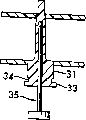
See also Fig. 5, shown in the figure is a kind of comparatively complex embodiments of the present invention.The chassis 31 of wherein said holder comprises a head 33 and the propelling pin 35 as driving element.Earlier described holder there is the base portion of head to insert in the hole of first flat board, first flat board is maintained by the groove below proximity heads portion 34.
See also Fig. 6 and 7, as described in the various embodiments described above, first elasticity rear to rhabodoid partly stretches and forms swollen convex portion then to install second flat board, but, is to utilize pin to stretch in a side of flat board 17 to described clamping element.This pin or can make with the elastomeric material mold pressing perhaps can be assembled the operational phase afterwards.This pin has a bar portion 38 and a head 36.The pin end can have one with this clamping element duct in the corresponding retaining groove 41 of narrow maintenance sleeve to catch this pin.
As shown in Figure 6, push the head 36 of the pin that is positioned at described holder base portion, the opposite end of rear 37 that just can stretch, and enter dull and stereotyped 11.In the time will discharging pin 35 applied pressures as shown in Figure 7, swollen protuberance 39 just can remain on flat board 11 the ring-type position of 40 belows, chassis with pressing.If unload flat board 11, can press pad 35 once more, swollen protuberance 39 is disappeared, allow dull and stereotyped 11 can on rear 37, back move.In this embodiment, the barrel-shaped part on chassis 40 can determine the spacing between the flat board.
See also Fig. 8, shown in the figure is another embodiment, wherein utilizes the elastic partition member that combines with a kind of metallic retainer 51, provides to electrically contact between two separated flat boards.This metallic retainer 51 can be carried out permanent the connection with first extending dull and stereotyped 53 by riveting portion 55.Rivet voluntarily the characteristic 55 except this, this retainer also has 57 and through holes 59 of a countersunk (counterbore).The elastic part of this distance piece, can or rivet voluntarily retainer 51 install before or be assemblied in afterwards in this ductility flat board 53, because the through hole of this retainer is the same with dull and stereotyped hole, diameter when its size discharges less than rear 50 tensile forces, swollen convex portion 52 that itself just can be by clamping with dull and stereotyped 54 assemblings before be connected with this retainer.By assembling plate shown in above-mentioned Fig. 1-3 time, dull and stereotyped 54 just can contact with retainer securely, and can provide between flat board 53 and 54 on demand and electrically contact.Also can by directly in the elastic partition member material molded conductive material reach conductive condition and do not need retainer.Also can utilize the simple metal sleeve or the compression sleeve that are inserted on the elastic partition member chassis 56 to reach this purpose.
See also Fig. 9, shown in the figure is to utilize and the insert structure of riveting the different another kind of quick formula retainer of retainer voluntarily shown in Figure 8.This retainer 61 can insert in any flat board temporarily, and does not need image pattern 8 to adopt extending flat board like that.This retainer 61 has a countersunk and a through hole, and this just also has a quick fastening projection 63 and a head 65 to match basically with shown in Figure 8 the same in addition, substitutes the riveted joint mode to reach the snapping effect.This embodiment can be used for basically among the assembling with the described identical all flat boards of Fig. 8 embodiment.
According to above-mentioned each preferred embodiment, can clearly be seen that the present invention can reach many purposes and have many advantages.Elastic partition member of the present invention is not limited to utilize certain special material.Various elastic partition member can not produce the metal fragment or the part that can cause electronic device to damage.There is not screw unexpected to fall on the sensitive equipment yet.In assembling or dismantle each and also do not need what specific purpose tool aspect dull and stereotyped.Assemble easily and dismantle and to save the repair time that is used to get rid of loose bolts.This described clamper can conveniently assemble and disassemble and can not damaged flat board or holder.Simultaneously, this dull and stereotyped elastomeric material can also be used as electrical insulation or electric-conductor.Hardware can be packed into molded or later in this holder, electrically contacts or the usefulness of ground connection to provide.Also can on the part of this holder, add a kind of binder, one flat plate wherein be holed and exempt.This holder keeps the mode of various parts, can make it unlikely occur in that all rapid plug-in plastic fasteners of prior art aspect once occurred, because of vibrations or impact caused loosening.This shows that the present invention obviously can overcome the many problems that run in all in the past plate pack packing techniques system.
Should also be noted that and be proficient in the professional and technical personnel, obviously can also propose some other change and change, but these changes and change all drop within protection scope of the present invention the present invention according to foregoing.Because scope of the present invention only is subjected to the restriction of following claim and their legal equivalents part.
Claims (19)
1. plate pack piece installing, it is fixed by the non-threaded holder that elastomeric material constitutes, and this plate pack piece installing comprises:
An elastic clamping pieces, it comprises:
A bottom of amplifying at rhabodoid one end diameter; And
A length elasticity rhabodoid that begins to extend from described bottom, described rhabodoid has two kinds of size states: first kind of state is relaxation state, the essentially no external force effect of this described rhabodoid this moment; Second kind of state is the extended state of described rhabodoid, and applied an axial tensile force this moment on described rhabodoid, it is stretched to the state of reduced;
Standing part on the described holder, it is used for first flat board is fixed on holder;
One second flat board, a hole is arranged on it, the diameter of the diameter in hole during greater than described second kind of extended state of described rhabodoid, and less than the diameter of described rhabodoid when first kind of release conditions, described rhabodoid insert in the described hole on this described second flat board; And
Swollen convex portion on the one described rhabodoid, it effectively contacts the back side of second flat board in the direction of first flat board, described swollen convex portion is by the described rhabodoid under second kind of tension state is inserted the described hole of described second flat board earlier, and then discharges the described tensile force that applies and form.
2. the assembly of flat board as claimed in claim 1, it is characterized in that, it also comprises the formation compartment, this compartment is the area part that the rhabodoid diameter increases, its diameter is greater than the diameter in described second hole, its position is between described two flat boards, makes this two dull and stereotyped maintenance from a distance.
3. elastomer holder is characterized in that it comprises:
A diameter enlarged head portion, it is formed on the end of an axially extended rhabodoid, and described head comprises an end face;
The described head of adjacency is with described holder and dull and stereotyped fixing standing part; With
The elasticity rear part of the longitudinal extension of the described rhabodoid that one diameter dwindles, this rear part can form two kinds of sizes: the size of relaxation state in first kind, this moment, this described rhabodoid was basically without any the external force effect; The size of second extended state of described rhabodoid, have an axial tensile force to put on this described rhabodoid this moment, its is stretched and dwindles its diameter.
4. holder as claimed in claim 3, it is characterized in that, it also comprise one with described rhabodoid base portion that fuse, that diameter increases, described base portion extends axially along described rhabodoid, between the head and described rear of described holder, its diameter is less than the diameter of described head.
5. holder as claimed in claim 4 is characterized in that, described standing part is the deformable annular groove of the described base portion of a contiguous described head.
6. holder as claimed in claim 4 is characterized in that, also comprises a retainer around described base portion, and described retainer is included in the standing part of the end face of the contiguous described head of one end.
7. holder as claimed in claim 6 is characterized in that described retainer is metal.
8. holder as claimed in claim 7 is characterized in that, described standing part is a kind of riveting portion.
9. holder as claimed in claim 4, it is characterized in that, comprise that also one has the inside axial blind hole of an end wall near described rhabodoid far-end, and one in described blind hole its length greater than the pin of described blind hole, this pin extends outside the described head, if should push described blind hole by described pin, described elastomer rear lengthwise is extended.
10. holder as claimed in claim 2 is characterized in that, described compartment offsets with described second flat board.
11. holder as claimed in claim 5, it is made by a kind of elastomeric material fully.
12. a plate pack piece installing, it is fixed by the holder of non-threaded elastomeric material, and this plate pack piece installing comprises:
An elastic clamping pieces, it comprises:
The head that diameter is bigger;
The base portion of one contiguous described head, described base portion is the part of described rhabodoid, its diameter is big slightly but less than described head; With
An elongated rod shape body that extends from base portion, described rhabodoid has perfectly smooth surface, can have two kinds of sizes: first kind is the size of relaxation state, this moment, this described rhabodoid did not have applied external force substantially; With the size of second kind of extended state of described rhabodoid, have an axial tensile force to put on described rhabodoid this moment, and it is stretched to the state of reduced;
One is fixed on first flat board of described head;
One second flat board, it has a hole, the diameter of its diameter during, and the diameter when being in first kind of relaxation state greater than described second kind of extended state of described rhabodoid, described rhabodoid passes described hole; With
Swollen convex portion in the one described rhabodoid, it effectively contacts the back side of described second flat board in the first dull and stereotyped direction, described swollen convex portion can pass the described hole of described second flat board when being in second kind of extended state at described rhabodoid, discharges described tensile force then and forms.
13. holder as claimed in claim 3 is characterized in that, described rhabodoid comprises a prehensile far-end, is used for rhabodoid is applied tensile force.
14. holder as claimed in claim 3 is characterized in that, the described rear of described rhabodoid partly has perfectly smooth outer surface.
15. holder as claimed in claim 7 is characterized in that, described standing part is a kind of riveting portion.
16. flat component as claimed in claim 1, described standing part are a kind of binders that can be added on its base.
17. holder as claimed in claim 7 is characterized in that, described retainer is metal, and it is fixed in the described base portion of described rhabodoid.
18. flat component as claimed in claim 1 is characterized in that, described standing part comprises that one is fixed in the retainer on the described base, described retainer described first flat board of can packing into apace.
19. flat component as claimed in claim 18 is characterized in that, described retainer is metal.
Applications Claiming Priority (2)
| Application Number | Priority Date | Filing Date | Title |
|---|---|---|---|
| US25537400P | 2000-12-15 | 2000-12-15 | |
| US60/255,374 | 2000-12-15 |
Publications (1)
| Publication Number | Publication Date |
|---|---|
| CN1481291A true CN1481291A (en) | 2004-03-10 |
Family
ID=22968030
Family Applications (1)
| Application Number | Title | Priority Date | Filing Date |
|---|---|---|---|
| CNA018206948A Pending CN1481291A (en) | 2000-12-15 | 2001-12-04 | Resilient standoff fastener |
Country Status (9)
| Country | Link |
|---|---|
| EP (1) | EP1355761A4 (en) |
| JP (1) | JP2004515929A (en) |
| KR (1) | KR20040014429A (en) |
| CN (1) | CN1481291A (en) |
| AU (1) | AU2002220044A1 (en) |
| CA (1) | CA2429547A1 (en) |
| MX (1) | MXPA03005276A (en) |
| TW (1) | TW524731B (en) |
| WO (1) | WO2002047866A1 (en) |
Cited By (1)
| Publication number | Priority date | Publication date | Assignee | Title |
|---|---|---|---|---|
| CN101095202B (en) * | 2004-12-28 | 2011-05-25 | 罗伯特·博世有限公司 | Device for inserting a power supply cable |
Families Citing this family (1)
| Publication number | Priority date | Publication date | Assignee | Title |
|---|---|---|---|---|
| GB0721325D0 (en) | 2007-10-31 | 2007-12-12 | Rolls Royce Plc | fastener arrangements |
Family Cites Families (7)
| Publication number | Priority date | Publication date | Assignee | Title |
|---|---|---|---|---|
| US2590264A (en) * | 1946-08-24 | 1952-03-25 | Ohio Rubber Co | Sleeve type fastening device for resilient plastic articles and the like |
| US3330522A (en) * | 1965-12-10 | 1967-07-11 | Clevite Corp | Vibration isolating mount |
| AU497866B2 (en) * | 1975-06-11 | 1979-01-18 | Mackay Consolidated Industries Pty. Ltd. | Anti-vibration fastener |
| US5190482A (en) * | 1990-11-13 | 1993-03-02 | Electro-Wire Products, Inc. | Bulkhead connector assembly |
| GB2309998A (en) * | 1996-02-06 | 1997-08-13 | Lee Patrick Mullins | Retaining device |
| US5980325A (en) * | 1998-07-30 | 1999-11-09 | Berg Technology, Inc. | Micro miniature electrical connector and method of manufacture |
| US6343827B1 (en) * | 2000-06-08 | 2002-02-05 | John P. Nepper, Sr. | Bridgelike connector (axially extending between apertured leadward rigid-sheet and trailward fixture-bar(s) ) |
-
2001
- 2001-12-04 CA CA002429547A patent/CA2429547A1/en not_active Abandoned
- 2001-12-04 JP JP2002549427A patent/JP2004515929A/en not_active Withdrawn
- 2001-12-04 WO PCT/US2001/045359 patent/WO2002047866A1/en not_active Application Discontinuation
- 2001-12-04 KR KR10-2003-7007423A patent/KR20040014429A/en not_active Application Discontinuation
- 2001-12-04 CN CNA018206948A patent/CN1481291A/en active Pending
- 2001-12-04 MX MXPA03005276A patent/MXPA03005276A/en unknown
- 2001-12-04 AU AU2002220044A patent/AU2002220044A1/en not_active Abandoned
- 2001-12-04 EP EP01270405A patent/EP1355761A4/en not_active Withdrawn
- 2001-12-14 TW TW090131001A patent/TW524731B/en not_active IP Right Cessation
Cited By (1)
| Publication number | Priority date | Publication date | Assignee | Title |
|---|---|---|---|---|
| CN101095202B (en) * | 2004-12-28 | 2011-05-25 | 罗伯特·博世有限公司 | Device for inserting a power supply cable |
Also Published As
| Publication number | Publication date |
|---|---|
| CA2429547A1 (en) | 2002-06-20 |
| MXPA03005276A (en) | 2003-09-25 |
| KR20040014429A (en) | 2004-02-14 |
| WO2002047866A1 (en) | 2002-06-20 |
| JP2004515929A (en) | 2004-05-27 |
| AU2002220044A1 (en) | 2002-06-24 |
| EP1355761A4 (en) | 2005-03-16 |
| TW524731B (en) | 2003-03-21 |
| EP1355761A1 (en) | 2003-10-29 |
Similar Documents
| Publication | Publication Date | Title |
|---|---|---|
| CN2672712Y (en) | Fixing device | |
| US7489511B2 (en) | Heat sink clip | |
| KR100942004B1 (en) | Fastening assembly having spacer and process of releasing said fastening assembly | |
| CN101937257A (en) | Portable computer | |
| JP2015506448A (en) | Self-indexing nut plate | |
| KR20070108137A (en) | Spring loaded spacer | |
| CN1481291A (en) | Resilient standoff fastener | |
| CN2900999Y (en) | Fixing device | |
| EP2991178A1 (en) | Clamp for panel-mounted electronics modules or other devices | |
| JP2000304020A (en) | Fastening device and fastening method | |
| TWI617101B (en) | Fastening structure, electronic assembly and operating method of fastening structure | |
| CN215719997U (en) | Expanding lock | |
| CN105472934A (en) | Universal shockproof device for circuit board | |
| US20040045147A1 (en) | Resilient standoff fastener | |
| KR101203957B1 (en) | Antenna holder for vehicle | |
| CN2925016Y (en) | Plate-article fixing mechanism | |
| CN219954828U (en) | LED spliced screen connecting assembly | |
| CN214092635U (en) | Novel expansion nut | |
| US11147178B2 (en) | Pre-strain unit for a T-bolt | |
| KR101559932B1 (en) | Antenna holder for vehicle comprising cable protection part | |
| CN221251527U (en) | Quick dismantlement changes vehicle test fixture of radar | |
| CN114961414B (en) | Protective device for highway engineering construction | |
| CN212740367U (en) | Connecting component of truss and escalator or pedestrian path truss | |
| JP2011137532A (en) | Fixture, fastening method of the same and unfastening method | |
| CN100419284C (en) | Serviceable w-base fastener |
Legal Events
| Date | Code | Title | Description |
|---|---|---|---|
| C06 | Publication | ||
| PB01 | Publication | ||
| C10 | Entry into substantive examination | ||
| SE01 | Entry into force of request for substantive examination | ||
| C02 | Deemed withdrawal of patent application after publication (patent law 2001) | ||
| WD01 | Invention patent application deemed withdrawn after publication |