CN1470764A - Wind-driven generator set with high energy output - Google Patents
Wind-driven generator set with high energy output Download PDFInfo
- Publication number
- CN1470764A CN1470764A CNA031484808A CN03148480A CN1470764A CN 1470764 A CN1470764 A CN 1470764A CN A031484808 A CNA031484808 A CN A031484808A CN 03148480 A CN03148480 A CN 03148480A CN 1470764 A CN1470764 A CN 1470764A
- Authority
- CN
- China
- Prior art keywords
- air
- generator
- generating set
- power generating
- blade
- Prior art date
- Legal status (The legal status is an assumption and is not a legal conclusion. Google has not performed a legal analysis and makes no representation as to the accuracy of the status listed.)
- Pending
Links
Images
Classifications
-
- F—MECHANICAL ENGINEERING; LIGHTING; HEATING; WEAPONS; BLASTING
- F03—MACHINES OR ENGINES FOR LIQUIDS; WIND, SPRING, OR WEIGHT MOTORS; PRODUCING MECHANICAL POWER OR A REACTIVE PROPULSIVE THRUST, NOT OTHERWISE PROVIDED FOR
- F03D—WIND MOTORS
- F03D9/00—Adaptations of wind motors for special use; Combinations of wind motors with apparatus driven thereby; Wind motors specially adapted for installation in particular locations
- F03D9/20—Wind motors characterised by the driven apparatus
- F03D9/25—Wind motors characterised by the driven apparatus the apparatus being an electrical generator
-
- F—MECHANICAL ENGINEERING; LIGHTING; HEATING; WEAPONS; BLASTING
- F03—MACHINES OR ENGINES FOR LIQUIDS; WIND, SPRING, OR WEIGHT MOTORS; PRODUCING MECHANICAL POWER OR A REACTIVE PROPULSIVE THRUST, NOT OTHERWISE PROVIDED FOR
- F03D—WIND MOTORS
- F03D80/00—Details, components or accessories not provided for in groups F03D1/00 - F03D17/00
- F03D80/30—Lightning protection
-
- F—MECHANICAL ENGINEERING; LIGHTING; HEATING; WEAPONS; BLASTING
- F03—MACHINES OR ENGINES FOR LIQUIDS; WIND, SPRING, OR WEIGHT MOTORS; PRODUCING MECHANICAL POWER OR A REACTIVE PROPULSIVE THRUST, NOT OTHERWISE PROVIDED FOR
- F03D—WIND MOTORS
- F03D80/00—Details, components or accessories not provided for in groups F03D1/00 - F03D17/00
- F03D80/40—Ice detection; De-icing means
-
- F—MECHANICAL ENGINEERING; LIGHTING; HEATING; WEAPONS; BLASTING
- F03—MACHINES OR ENGINES FOR LIQUIDS; WIND, SPRING, OR WEIGHT MOTORS; PRODUCING MECHANICAL POWER OR A REACTIVE PROPULSIVE THRUST, NOT OTHERWISE PROVIDED FOR
- F03D—WIND MOTORS
- F03D80/00—Details, components or accessories not provided for in groups F03D1/00 - F03D17/00
- F03D80/60—Cooling or heating of wind motors
-
- H—ELECTRICITY
- H02—GENERATION; CONVERSION OR DISTRIBUTION OF ELECTRIC POWER
- H02K—DYNAMO-ELECTRIC MACHINES
- H02K7/00—Arrangements for handling mechanical energy structurally associated with dynamo-electric machines, e.g. structural association with mechanical driving motors or auxiliary dynamo-electric machines
- H02K7/18—Structural association of electric generators with mechanical driving motors, e.g. with turbines
- H02K7/1807—Rotary generators
- H02K7/1823—Rotary generators structurally associated with turbines or similar engines
- H02K7/183—Rotary generators structurally associated with turbines or similar engines wherein the turbine is a wind turbine
- H02K7/1838—Generators mounted in a nacelle or similar structure of a horizontal axis wind turbine
-
- F—MECHANICAL ENGINEERING; LIGHTING; HEATING; WEAPONS; BLASTING
- F05—INDEXING SCHEMES RELATING TO ENGINES OR PUMPS IN VARIOUS SUBCLASSES OF CLASSES F01-F04
- F05B—INDEXING SCHEME RELATING TO WIND, SPRING, WEIGHT, INERTIA OR LIKE MOTORS, TO MACHINES OR ENGINES FOR LIQUIDS COVERED BY SUBCLASSES F03B, F03D AND F03G
- F05B2220/00—Application
- F05B2220/70—Application in combination with
- F05B2220/706—Application in combination with an electrical generator
- F05B2220/7064—Application in combination with an electrical generator of the alternating current (A.C.) type
- F05B2220/70642—Application in combination with an electrical generator of the alternating current (A.C.) type of the synchronous type
-
- F—MECHANICAL ENGINEERING; LIGHTING; HEATING; WEAPONS; BLASTING
- F05—INDEXING SCHEMES RELATING TO ENGINES OR PUMPS IN VARIOUS SUBCLASSES OF CLASSES F01-F04
- F05B—INDEXING SCHEME RELATING TO WIND, SPRING, WEIGHT, INERTIA OR LIKE MOTORS, TO MACHINES OR ENGINES FOR LIQUIDS COVERED BY SUBCLASSES F03B, F03D AND F03G
- F05B2220/00—Application
- F05B2220/70—Application in combination with
- F05B2220/706—Application in combination with an electrical generator
- F05B2220/7066—Application in combination with an electrical generator via a direct connection, i.e. a gearless transmission
-
- F—MECHANICAL ENGINEERING; LIGHTING; HEATING; WEAPONS; BLASTING
- F05—INDEXING SCHEMES RELATING TO ENGINES OR PUMPS IN VARIOUS SUBCLASSES OF CLASSES F01-F04
- F05B—INDEXING SCHEME RELATING TO WIND, SPRING, WEIGHT, INERTIA OR LIKE MOTORS, TO MACHINES OR ENGINES FOR LIQUIDS COVERED BY SUBCLASSES F03B, F03D AND F03G
- F05B2220/00—Application
- F05B2220/70—Application in combination with
- F05B2220/706—Application in combination with an electrical generator
- F05B2220/7068—Application in combination with an electrical generator equipped with permanent magnets
-
- F—MECHANICAL ENGINEERING; LIGHTING; HEATING; WEAPONS; BLASTING
- F05—INDEXING SCHEMES RELATING TO ENGINES OR PUMPS IN VARIOUS SUBCLASSES OF CLASSES F01-F04
- F05B—INDEXING SCHEME RELATING TO WIND, SPRING, WEIGHT, INERTIA OR LIKE MOTORS, TO MACHINES OR ENGINES FOR LIQUIDS COVERED BY SUBCLASSES F03B, F03D AND F03G
- F05B2260/00—Function
- F05B2260/20—Heat transfer, e.g. cooling
- F05B2260/205—Cooling fluid recirculation, i.e. after having cooled one or more components the cooling fluid is recovered and used elsewhere for other purposes
-
- Y—GENERAL TAGGING OF NEW TECHNOLOGICAL DEVELOPMENTS; GENERAL TAGGING OF CROSS-SECTIONAL TECHNOLOGIES SPANNING OVER SEVERAL SECTIONS OF THE IPC; TECHNICAL SUBJECTS COVERED BY FORMER USPC CROSS-REFERENCE ART COLLECTIONS [XRACs] AND DIGESTS
- Y02—TECHNOLOGIES OR APPLICATIONS FOR MITIGATION OR ADAPTATION AGAINST CLIMATE CHANGE
- Y02E—REDUCTION OF GREENHOUSE GAS [GHG] EMISSIONS, RELATED TO ENERGY GENERATION, TRANSMISSION OR DISTRIBUTION
- Y02E10/00—Energy generation through renewable energy sources
- Y02E10/70—Wind energy
- Y02E10/72—Wind turbines with rotation axis in wind direction
Landscapes
- Engineering & Computer Science (AREA)
- Life Sciences & Earth Sciences (AREA)
- Sustainable Energy (AREA)
- Sustainable Development (AREA)
- Mechanical Engineering (AREA)
- Combustion & Propulsion (AREA)
- Chemical & Material Sciences (AREA)
- General Engineering & Computer Science (AREA)
- Power Engineering (AREA)
- Physics & Mathematics (AREA)
- Thermal Sciences (AREA)
- Wind Motors (AREA)
- Connection Of Motors, Electrical Generators, Mechanical Devices, And The Like (AREA)
- Control Of Eletrric Generators (AREA)
Abstract
A wind generator unit with high energy yield, comprising an air-motor or air-generator, capable of transforming the kinetic energy of the wind into electrical energy, wherein the electrical generator (22) of the air-motor is directly and closely connected with the rotor (18) of the air-motor, so as to obtain a higher overall yield with respect to conventional units; moreover, the air-motor, particularly suitable for mountainous installations and extremely windy areas, is able to capture a high amount of wind energy in a determined time period, being further equipped with anti-ice and anti-lightning systems.
Description
Technical field
The present invention relates to have the wind power generating set of high-energy output.
More specifically, the unit that the present invention relates to comprises wind-force or air motor generator, and its ratio that provides between power and its structure weight is high especially, also is suitable for being installed in open-air windy area.
Background technique
In " cleaning " alternative energy, in other words, low to environmental impact or do not have in the alternative energy of environmental impact, wind-force has the meaning of particular importance, has the area of stable wind-force particularly like this probably in the whole year especially.In these areas, the interest in mountain area is bigger, for example the wide geographic area of Italy and Iberia Peninsula.
To this, there is different technical solutions in the mechanical aspects that converts electric energy at relative kinetic energy with wind.Such machinery is commonly referred to wind-driven generator (air generator) or air motor, and the ratio between the electric energy of himself weight and production is very high usually.In addition, relatively they give fixed structure, and actual machine itself they be difficult to assembling in essence, in structure, comprise the supporting tower, it is own with its function of abundant realization that machinery is installed thereon.
These conditions have limited the power that this class can be installed on mountain area and machinery under extreme conditions greatly, but since their wind-force feature still meet with much recognition.
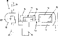
In order to show the technological deficiency of prior art better, preferably the structure of the air motor built according to the standing state of this technology is carried out comprehensive analysis, it tentatively illustrates in Fig. 1.
Air motor is showed with the signal exploded view among the figure, do not express wind sensor, blade and point to the azimythal angle rotary member that driver, gondola support tower relatively, and electronic control and power device, such as transducer, particularly control the transducer of the parameter of energy that generator is produced, be used to make these parameters to be fit to accept the parameter of the main electrical network of this energy.
The air motor of Fig. 1 comprises the supporting tower 10 of container 11 usefulness, container 11 limits gondola 12, and gondola 12 comprises inner gimbal 13, is used to hold generator 14, and finish with corresponding rotor 15, it is connected to multiplying gear 17 by suitable connecting joint 16.
Can be clear that by Fig. 1 common air motor has total tangible interval between rotor 18 and generator 14.Multiplying gear 17 is inserted between them in addition, and it increases the basic rotating speed relevant with wind-force intensity of rotor 18, so that it adapts to the necessary rotating speed of generator 14 tradition operations.
Another defective workmanship that also exists in the existing wind generator set and air motor in the mountain area/negative results that the use of position, hills is derived is relevant, but when taking into full account ecology and require, these mountain areas/position, hills constitutes and obtains the required zone with highly good atmospheric conditions of electric energy.
Be used for the traditional the most obvious problem that air generator ran into of this type of device mainly due to:
-be difficult to enter mountain area/position, hills, adopt quite accurate mechanism to transport and to install heavy, complicated mechanical;
The feature of-wind, the intensity of blowing often changes, and fitful wind and vortex will convert the structural stress of air motor to;
-disadvantageous atmospheric conditions, they show along with high atmospheric moisture and cooling form a large amount of ice, and the bombardment of the lightning in squally.
Exactly because these reasons, the Power Limitation of modern air generator group that is installed in the position, mountain area is within 600 watts, so that make aforementioned difficulties be positioned at acceptable limit.
In addition, because wind blows with fitful wind, vortex and the rapid change of wind direction, two class problems occur, a class is caused by the mutability of the dynamics stress of structure, acts on structural power and changes its intensity, direction and point of action pulsedly; The appearance of another kind of problem is relevant for the requirement of strong stretching/absorptivity and Buckling stress with structure, and they must be distributed on the different component, and discharges on other member, and does not damage, and does not have the dangerous feature of sparking of sustained oscillation.At last, with regard to the adverse atmospheric condition of being considered, should remember that all wind power generating set all are effective more, then for the power of same amount, more can be at the fixed time during (for example in 1 year), more energy is provided.This also depends on the availability of unit, or can be owing to various obstacles, is deposited on the blade or because lightning-strike is damaged, is reduced to minimum the mechanical downtime that causes such as ice.
Summary of the invention
Therefore, by aforementioned requirement, the objective of the invention is, realize a kind of like this wind power generating set with high-energy output, it is particularly suitable for utilizing the wind energy of mountain area/position, hills, thus in the given time lag with under identical power, relatively common unit provide more energy.
Another object of the present invention is to realize a kind of like this wind power generating set with high-energy output, and the relative power that it can send of the air motor that it comprised is special light.
Another purpose of the present invention is to realize a kind of like this wind power generating set with high-energy output; it can absorb the dangerous feature of strong stretching/compression and Buckling stress and/or sustained oscillation; it can also make machinery because operate miss and various obstacle; particularly because the obstacle that the unfavourable weather condition causes; and be reduced to minimum the dead time that causes, or even eliminate.
The last but not least purpose of the present invention is to realize a kind of like this wind power generating set with high-energy output, no matter which kind of usage requirement, it can both move especially effectively and be reliable, and common relatively unit also is easy to install.
These and other some purpose of the present invention will be finished by realizing a kind of wind power generating set with high-energy output, and for the sake of simplicity, we claim a kind of like this wind power generating set with high-energy output to build according to claim 1.
Its superiority is, the wind power generating set that the present invention proposes is used can be installed in the position, mountain area (according to ecological requirement, they have be to obtain the required good especially atmospheric conditions of electric energy) air generator or air motor group, the relative power that is developed, its structure light especially (sending power and reached 1200 watts, in other words is the known air generator set twice of energy output power now).
In order to obtain a kind of like this structure, the machinery (for example removing rotating speed multiplication member) that a kind of relative conventional solution number of components reduces is proposed, from mechanical viewpoint, these parts major parts are in one.
The rapid reduction of mechanical component is by corresponding complicated offset of power (electric energy is more handled) with the electronic component of control (the time constant harmony mutually that adjustment process and lower machinery inertial are derived) two aspects.
The different mechanical structures of air generator also require special aerodynamic studies, so that the intensity of limiting structure vibration frequency, thereby avoid causing the dangerous feature of sustained oscillation.
Really, by computer simulation structure is carried out careful air-elasticity and researched and solved these problems, the program of using in the computer simulation is based upon on the model basis of the feature of reproducing institute's research structure.Such software program is set up for concrete the application specially, is applicable to determine the best distribution of stress on the different parts of structure, stress is shared pari passu, so that bear them safely.
These software programs are also intervened regulating system, thereby with suitable approach control transient phenomenon, for example when fitful wind occurring suddenly, intervene the orientation of rotor blade fast, thereby restrict rotor and all are placed on stress on the parts in downstream greatly.
More generally say, if being arranged, an energy spikes delivers to air generator from hearsay, excessive effective all parameters of system of connections rapidly of regulating, thereby such spike can flow along the member chain of unit until the main distribution net, and can be in some member energy-producing moment pile up, make them suffer improper stress.
Description of drawings
The feature and advantage of the wind power generating set with high-energy output that the present invention proposes will be by the following explanation that relates to the indefiniteness example embodiment, and with reference to the accompanying drawings, becomes more clear, wherein:
-Fig. 1 is a schematic representation, and its expression is by the wind-driven generator or the air motor of existing techniques in realizing;
-Fig. 2 is the partial schematic side view of air motor, and this air motor is applied in the wind power generating set with high-energy output of the present invention's proposition;
-Fig. 3 has showed the part amplification of Fig. 2, the ice protection system passage of its expression the present invention proposition, and this ice protection system is realized in air motor blade circulates inside by hot air.
Embodiment
Specifically referring to Fig. 2, the parts of air motor among the figure (or air generator) such as its function are similar to those functions of components shown in Figure 1, then represent with same numeral, be to be noted that air motor that the present invention proposes with build by existing technology different greatly, at first be, different with the generator 14 of common structure among the figure with 22 generators of representing, be directly to be connected on the rotor 18, and in new structure, removed multiplying gear 17 with corresponding joint 16 with interval very near-earth.
For this basic result of the rotor 18 that obtains to make generator 22 be connected directly to blade 21, described generator 22 is built with complete natural formation, and some is different from common generator 14.
At first, generator 22 has fully special size, it be flat (very thin along its length), but very wide along diametric(al).More particularly, by more excellent indefiniteness example embodiment of the present invention, synchronous, the multipole and polyphase generator 22 with permanent magnet is used for directly being connected (as twin shaft to magnetic gap), without any excitation wires, without any the slippage contact, it moves with very low rotating speed.
Generator 22 also mechanically has whole supporting structure, the utmost point wheel (polar wheel) that constitutes generator amature is connected to centerbody 20 with flange, and stator is connected to framework 13 with flange, thereby 12 of gondolas are made of three parts, specifically, constitute by centerbody 20, generator 22 and framework 13.
Thereby new solution has been reduced weight, parts and drive system the biglyyest, because multiplying gear 17 and remaining hydraulic package, transmission shaft and joint are removed from structure.This structure of air generator also gets so that the structure of bearing support 10 can alleviate greatly, and its general size is very big, and is quite heavy in whole unit.
In addition, the air generator that the present invention proposes has higher total output compared with common structure, because it has removed the excitation wires of multiplying gear 17 and generator 22 decisively.
Like this,, its transportation and installation are become easily, even under extreme conditions also like this according to this embodiment.
At last, described air generator has high utilization ratio, is used at certain time intervals collecting in (for example 1 year) wind energy of maximum quantity, and this is the crucial feature that unit is used economic consequence.Therefore, its final result is to have realized a kind of air generator, it have certain hour at interval between the energy of producing and the machinery weight at high proportion.All these is given the credit to by the variable pitch of blade 21 regulates, the grade of electricity and the self-excitation of each blade 21 is regulated power, and carries out orientation by the azimythal angle control of electricity operation by wind direction.Rotating speed also is variable in its certain limit.
As before mentioning, described air generator is particularly suitable for the mountain area device, because it has equipped anti-freeze and anti-lightning system.At this on the one hand, the purpose of the ice protection system that designs in the air generator of using in the wind power generating set that the present invention proposes be to shorten generator in the winter time in month because the time-out that causes that freezes on blade uses at interval, increase the utilization ratio of machinery.Really, the formation of ice can cause the aerodynamic force (ice causes the change of empennage profile geometric shape) that acts on the rotor 18 and the imbalance of centrifugal force (the non-homogeneous formation of ice), and the increase of the level of vibration of total has subsequently determined the pause of generator.
Therefore, machinery usually must keep stopping work, and especially in rugged environment, until the weather that thaws, is disadvantageous especially with the minimizing of the utilization ratio hour/year calculated.
The ice protection system that the present invention proposes is based in the inboard blow warm air of blade 21, wherein, the energy that discharges of the heat energy that discharges from transducer of the heat energy that is used for air heating, partial heat energy that generator 22 discharges and two groups of resistance being placed on container 11 inboards.
The acquisition of forced circulation also is installed in more same fans in the air-conditioning system of base of tower 10 by application, or the incorporated fan of suitably installing, and by utilizing ectoskeletal air draft effect.
For the operation of the ice protection system that the present invention proposes is described more fully, specifically can be with reference to figure 3.
Air sucks from the outside by the suitable slit that is equipped with filter, is installed in the base of tower 10, and is promoted upwards by suitable fan, flows through to reclaim thermal loss around transducer (not shown) housing.
Enter container 11, carry out directed mechanism 24 by wind direction before, run into the resistance exchanger 23 that constitutes main heating and other exchangers of generator 22 inboards from the cold air flow F of the base of tower 10, thereby this system can be used for also at cooled electric generator 22 when generator 22 moves in summer under full power.
So the thermal air current C that produces is drawn towards blade 21, be present in the inboard that film 25 in the centerbody 20 is sent to air in blade 21, herein, air-flow C is compelled to by passage membrane system 26 and opening, in differential mode, according to the distribution of most probable at the ice of outer wall formation, the internal surface of flushing whole blade 21.
Also may use a series of vortex generators that suitably are arranged in the blade internal surface, to increase the heat exchange coefficient of blade 21 inboards.
Then, air G by path flows to centerbody 20, and discharge in the hole 27 of the previous section by being produced on centerbody 20.
A kind of additional selection is to make outflow opening by appropriate intervals between centerbody 20 and each blade 21.
The heating system of using expects in this way air is sent in the structure that is generally hollow of blade 21 that even under the situation of loop sealing, also side realizes circulation within it.In practice, air heats by heat exchanging process, and air itself absorbs the thermal power of electromechanical and electric device dissipation and is present in the thermal power that resistance produces in the structure during the course.
When return openings, air stream sucks from the outside, is used to wash hot part, and when sealing in the loop, such air-flow periodically contacts thermal source so that it is carried out heat regeneration along the path of its blade inboard.
Be to be noted that at last that when air generator is stopped work heating is used to make ice sheet to break away from the surface of blade 21, utilize gravity then so that it is removed from machinery, and when air generator moved, the system that has been activated of freezing avoids in advance.
As mentioned above, heating part is dissipated by thermal loss and produces, part by suitably be arranged in the container 11 or directly be arranged in the centerbody 20, near blade 21 grapplings place resistance produces, forced circulation then obtains by the fan that is preset in the tower, and the air draft effect that provides owing to hollow structure is strengthened.
All these are by to output, to the energy morphological Study, and carry out to using blade that common blade and exploitation made by special geometry by special material or for the air circulation that promotes blade adjoining edge zone and heat exchange that the calculating of maximum thermal exchange obtains.
Also pre-insight has proposed long-term time-out and has used back at interval to the generator heating with strengthen the proper technology that makes that it is cooled off gradually after using, and the maintenance of vanepiston (affiliated parts in Fig. 3 with 28 expressions) sensor device of operation and all installations under the optimum climate condition.
This system combines air-conditioning and anti-freeze effect, and has utilized the hollow air discharge structure of whole air generator again.
Because considered the damage that lightning strike causes is reduced to the possibility of minimum, thereby increased the utilization ratio of the wind power generating set of the present invention's proposition, the ectoskeleton structure of described air motor then makes operation, use, particularly Faraday effect become easy.At last, for the operation part of protecting generator and the damage that rotational parts is not discharged, can use and receive structure (to classical spike theory) and bearing is positioned over position away from the lightning path.
By the explanation of having carried out, have the feature of the wind power generating set of high-energy output, purpose promptly of the present invention is just clear, and its superiority of erect image is also clear.
At last, the wind power generating set of being discussed obviously can have countless modifications, only however depart from for this reason invention thought intrinsic character of innovation, erect image is in the embodiment of the invention of reality, material, shown in the shape and size of details can decide as requested, and they can be replaced with technical equivalents.
Claims (12)
1. one kind has the wind power generating set that high-energy is exported, this wind power generating set is specially adapted to mountain area/hills equipment and/or the many zones of wind spy, described generator set comprises at least one air motor or air generator, can convert the kinetic energy of wind to electric energy, described air motor comprises at least one and is used for the rotor part (18) that holds the gondola (12) of a generator (14) at least and be equipped with a series of blades (21), it is characterized in that, described generator (22) directly is connected to the described rotor part (18) of air motor with spacing very near-earth, thereby obtains to be higher than total output of conventional unit.
2. wind power generating set as claimed in claim 1 is characterized in that, described generator (22) is arranged to be connected directly to the rotor (18) of described blade (21), and described generator (22) is according to flat and construct along the very wide surface of diameter.
3. wind power generating set as claimed in claim 1 is characterized in that, described generator (22) has permanent magnet, for synchronous, multipole and heterogeneous type, and without any excitation wires and/or slippage contact.
4. wind power generating set as claimed in claim 1, it is characterized in that, generator (22) mechanically is integral with the supporting structure of air motor, and have the rotor of the centerbody (20) that is connected to described rotor part (18) and be fixed to the stator of framework (13), described framework (13) is used to hold described gondola (12), and described gondola (12) is made of described centerbody (20), generator (22) and framework (13).
5. wind power generating set as claimed in claim 1 is characterized in that, described unit comprises a system, and this system is suitable for preventing going up at the described blade (21) of air motor and forms ice, and described system comprises and is suitable for air is imported device in the blade (21).
6. wind power generating set as claimed in claim 5 is characterized in that, the heat energy that the air that enters blade (21) has utilized the electromechanical that is present in described air motor inboard and/or electric device to dissipate is heated in advance.
7. wind power generating set as claimed in claim 6 is characterized in that, the heat energy that is used for heated air is provided by generator (22) and/or the resistor group (23) that is arranged on the air motor inboard.
8. wind power generating set as claimed in claim 7, it is characterized in that, air is by forced circulation means and utilize the air draft effect of the supporting tower (10) of described air motor to be transfused in the described blade (21), described air quantity is sucked by the outside by suitable slit, and is promoted upwards by fan assembly.
9. wind power generating set as claimed in claim 8, it is characterized in that, on described electric device and/or machinery and/or resistance, transfer to blade (21) by lane device (25,26) by cool air (F) by the hot air flow (C) that produces, lane device (25,26) is in differential mode, according to the ice distribution that most probable forms on the outer wall of described blade (21), carry described hot air flow (C), to wash the internal surface of each blade (21).
10. wind power generating set as claimed in claim 9 is characterized in that, described lane device (25,26) comprises a series of vortex generators, in order to increase the inboard heat exchange coefficient of each blade (21).
11. wind power generating set as claimed in claim 9, it is characterized in that, described hot air flow (C) in blade (21) inner channel is by the described centerbody (20) of the path flow of determining to rotor structure (18), and be expelled to the outside by being made at least one opening (27) on the centerbody (20), thereby realized the circulation of hot air flow (C) in each blade (21) structure inboard, described hot air flow (C) is given the credit to heat exchanging process and is obtained heating, in heat exchanging process, thermal power that described electromechanical of absorption of air and electric device dissipate and the thermal power that is present in described resistance (23) generation in the air motor.
12. wind power generating set as claimed in claim 1 is characterized in that, it has comprised the protective equipment of avoiding lightning and/or other harmful weather condition impact.
Applications Claiming Priority (2)
| Application Number | Priority Date | Filing Date | Title |
|---|---|---|---|
| IT001439A/2002 | 2002-06-28 | ||
| IT2002MI001439A ITMI20021439A1 (en) | 2002-06-28 | 2002-06-28 | HIGH ENERGY EFFICIENCY WIND GENERATION PLANT |
Publications (1)
| Publication Number | Publication Date |
|---|---|
| CN1470764A true CN1470764A (en) | 2004-01-28 |
Family
ID=11450112
Family Applications (1)
| Application Number | Title | Priority Date | Filing Date |
|---|---|---|---|
| CNA031484808A Pending CN1470764A (en) | 2002-06-28 | 2003-06-27 | Wind-driven generator set with high energy output |
Country Status (8)
| Country | Link |
|---|---|
| US (1) | US20040041408A1 (en) |
| EP (1) | EP1375913A1 (en) |
| JP (1) | JP2004251270A (en) |
| CN (1) | CN1470764A (en) |
| BR (1) | BR0301691A (en) |
| CA (1) | CA2433072A1 (en) |
| IT (1) | ITMI20021439A1 (en) |
| NO (1) | NO20032987L (en) |
Cited By (5)
| Publication number | Priority date | Publication date | Assignee | Title |
|---|---|---|---|---|
| CN103080537A (en) * | 2010-06-24 | 2013-05-01 | 瑞能系统欧洲股份公司 | Rotor blade de-icing |
| WO2013097414A1 (en) * | 2011-12-31 | 2013-07-04 | 江苏新誉重工科技有限公司 | Temperature regulating system for wind generator set |
| CN103958890A (en) * | 2011-11-17 | 2014-07-30 | 乌本产权有限公司 | Wind turbine rotor blade and method for deicing a wind turbine rotor blade |
| CN104160147A (en) * | 2011-12-21 | 2014-11-19 | 维斯塔斯风力系统集团公司 | De-icing of a wind turbine blade |
| CN104169576A (en) * | 2012-01-20 | 2014-11-26 | 维斯塔斯风力系统集团公司 | Method of de-icing a wind turbine blade |
Families Citing this family (69)
| Publication number | Priority date | Publication date | Assignee | Title |
|---|---|---|---|---|
| ITBZ20010043A1 (en) | 2001-09-13 | 2003-03-13 | High Technology Invest Bv | ELECTRIC GENERATOR OPERATED BY WIND ENERGY. |
| DE10337534B4 (en) | 2003-08-14 | 2019-12-12 | W2E Wind To Energy Gmbh | Wind energy converter with a rotor hub having an interior |
| ATE340932T1 (en) * | 2003-08-14 | 2006-10-15 | W2E Wind To Energy Gmbh | WIND ENERGY CONVERTER HAVING A ROTOR HUB HAVING AN INTERIOR |
| US7154193B2 (en) * | 2004-09-27 | 2006-12-26 | General Electric Company | Electrical machine with double-sided stator |
| US7154191B2 (en) | 2004-06-30 | 2006-12-26 | General Electric Company | Electrical machine with double-sided rotor |
| US7154192B2 (en) | 2004-09-27 | 2006-12-26 | General Electric Company | Electrical machine with double-sided lamination stack |
| ITBZ20040047A1 (en) | 2004-09-20 | 2004-12-20 | High Technology Invest Bv | ELECTRIC GENERATOR / MOTOR, IN PARTICULAR FOR USE IN WIND PLANTS, ROPE OR HYDRAULIC PLANTS. |
| DE102004064007B4 (en) * | 2004-09-24 | 2009-08-20 | Aloys Wobben | Wind turbine with a generator cooling |
| US7839048B2 (en) | 2004-09-27 | 2010-11-23 | General Electric Company | Electrical machine with double-sided stator |
| US7548008B2 (en) | 2004-09-27 | 2009-06-16 | General Electric Company | Electrical machine with double-sided lamination stack |
| DE102004058776B3 (en) | 2004-12-07 | 2006-07-13 | Nordex Energy Gmbh | Device for ventilating a rotor hub of a wind energy plant |
| US7692357B2 (en) | 2004-12-16 | 2010-04-06 | General Electric Company | Electrical machines and assemblies including a yokeless stator with modular lamination stacks |
| ITBZ20050062A1 (en) | 2005-11-29 | 2007-05-30 | High Technology Invest Bv | PERMANENT MAGNET ROTOR FOR GENERATORS AND ELECTRIC MOTORS |
| DK1934474T3 (en) | 2005-09-21 | 2010-06-21 | Wilic S A R L | Bearing gasket assembly with maze gasket and screw gasket combination |
| ITBZ20050063A1 (en) | 2005-11-29 | 2007-05-30 | High Technology Invest Bv | LAMIERINI PACKAGE FOR GENERATORS AND ELECTRIC MOTORS AND PROCEDURE FOR ITS IMPLEMENTATION |
| JP4814608B2 (en) * | 2005-10-21 | 2011-11-16 | 富士重工業株式会社 | Windmill |
| US8029239B2 (en) * | 2005-11-18 | 2011-10-04 | General Electric Company | Rotor for a wind energy turbine and method for controlling the temperature inside a rotor hub |
| US7245042B1 (en) | 2005-11-25 | 2007-07-17 | Simnacher Larry W | Auxiliary wind energy generation from a wind power generation apparatus |
| US7427814B2 (en) * | 2006-03-22 | 2008-09-23 | General Electric Company | Wind turbine generators having wind assisted cooling systems and cooling methods |
| JP4634508B2 (en) * | 2006-07-14 | 2011-02-16 | ビ−エイイ− システムズ パブリック リミテッド カンパニ− | Heat distribution in distributed lighting equipment. |
| US7857599B2 (en) * | 2007-01-10 | 2010-12-28 | General Electric Company | Method and apparatus for forming wind turbine machines |
| JP4994944B2 (en) | 2007-05-18 | 2012-08-08 | 三菱重工業株式会社 | Wind power generator |
| EP2000668A1 (en) * | 2007-06-06 | 2008-12-10 | ICEC Holding AG | Wind turbine tower with passive cooling |
| US8025480B1 (en) | 2007-06-08 | 2011-09-27 | Weldon W. Alders | Wind turbine blades with avian avoidance surfaces |
| DE102007049599A1 (en) * | 2007-10-15 | 2009-05-07 | Innovative Windpower Ag | Temperature control of coupled gearbox and generator in a wind turbine |
| JP4796039B2 (en) * | 2007-11-22 | 2011-10-19 | 三菱重工業株式会社 | Wind power generator |
| ITMI20081122A1 (en) | 2008-06-19 | 2009-12-20 | Rolic Invest Sarl | WIND GENERATOR PROVIDED WITH A COOLING SYSTEM |
| IT1390758B1 (en) | 2008-07-23 | 2011-09-23 | Rolic Invest Sarl | WIND GENERATOR |
| US8137074B2 (en) | 2008-08-21 | 2012-03-20 | General Electric Company | Wind turbine lightning protection system |
| US8047774B2 (en) * | 2008-09-11 | 2011-11-01 | General Electric Company | System for heating and cooling wind turbine components |
| DE102008050848A1 (en) | 2008-10-08 | 2010-04-15 | Wobben, Aloys | ring generator |
| IT1391939B1 (en) | 2008-11-12 | 2012-02-02 | Rolic Invest Sarl | WIND GENERATOR |
| IT1391770B1 (en) | 2008-11-13 | 2012-01-27 | Rolic Invest Sarl | WIND GENERATOR FOR THE GENERATION OF ELECTRICITY |
| ITMI20090403A1 (en) * | 2009-03-17 | 2010-09-18 | Linz Electric S R L | ROTARY MOTION METHOD OF A SOUNDPROOF WIND TURBINE. |
| IT1393937B1 (en) | 2009-04-09 | 2012-05-17 | Rolic Invest Sarl | WIND TURBINE |
| IT1393707B1 (en) | 2009-04-29 | 2012-05-08 | Rolic Invest Sarl | WIND POWER PLANT FOR THE GENERATION OF ELECTRICITY |
| SE535025C2 (en) * | 2009-06-08 | 2012-03-20 | Ge Wind Energy Norway As | Wind turbines and a method for operating a wind turbine |
| IT1394723B1 (en) | 2009-06-10 | 2012-07-13 | Rolic Invest Sarl | WIND POWER PLANT FOR THE GENERATION OF ELECTRICITY AND ITS CONTROL METHOD |
| IT1395148B1 (en) | 2009-08-07 | 2012-09-05 | Rolic Invest Sarl | METHOD AND APPARATUS FOR ACTIVATION OF AN ELECTRIC MACHINE AND ELECTRIC MACHINE |
| US7883313B2 (en) * | 2009-11-05 | 2011-02-08 | General Electric Company | Active flow control system for wind turbine |
| IT1397081B1 (en) | 2009-11-23 | 2012-12-28 | Rolic Invest Sarl | WIND POWER PLANT FOR THE GENERATION OF ELECTRICITY |
| IT1398060B1 (en) | 2010-02-04 | 2013-02-07 | Wilic Sarl | PLANT AND METHOD OF COOLING OF AN ELECTRIC GENERATOR OF AN AIR SPREADER, AND AIRCONDITIONER INCLUDING SUCH A COOLING PLANT |
| IT1399201B1 (en) | 2010-03-30 | 2013-04-11 | Wilic Sarl | AEROGENERATOR AND METHOD OF REMOVING A BEARING FROM A AIRCONDITIONER |
| IT1399511B1 (en) | 2010-04-22 | 2013-04-19 | Wilic Sarl | ELECTRIC GENERATOR FOR A VENTILATOR AND AEROGENER EQUIPPED WITH THIS ELECTRIC GENERATOR |
| US8038398B2 (en) * | 2010-10-06 | 2011-10-18 | General Electric Company | System and method of distributing air within a wind turbine |
| CN102465838A (en) * | 2010-10-31 | 2012-05-23 | 扬州神州风力发电机有限公司 | Vibration absorption structure for wind power generator |
| DE102010051296B4 (en) | 2010-11-12 | 2013-11-21 | Nordex Energy Gmbh | Rotor blade and method for deicing the rotor blade of a wind turbine |
| DE102010051293B4 (en) | 2010-11-12 | 2013-11-21 | Nordex Energy Gmbh | Rotor blade of a wind turbine |
| DE102010051297B4 (en) | 2010-11-12 | 2017-04-06 | Nordex Energy Gmbh | Rotor blade of a wind turbine |
| DE102010051292B4 (en) | 2010-11-12 | 2016-10-06 | Nordex Energy Gmbh | Rotor blade of a wind turbine |
| DE102010051295B4 (en) | 2010-11-12 | 2013-11-21 | Nordex Energy Gmbh | Rotor blade of a wind turbine |
| ITMI20110378A1 (en) | 2011-03-10 | 2012-09-11 | Wilic Sarl | ROTARY ELECTRIC MACHINE FOR AEROGENERATOR |
| ITMI20110375A1 (en) | 2011-03-10 | 2012-09-11 | Wilic Sarl | WIND TURBINE |
| ITMI20110377A1 (en) | 2011-03-10 | 2012-09-11 | Wilic Sarl | ROTARY ELECTRIC MACHINE FOR AEROGENERATOR |
| EP2505830B1 (en) | 2011-03-31 | 2016-08-03 | Alstom Wind, S.L.U. | Wind turbine |
| US8678767B2 (en) * | 2011-04-08 | 2014-03-25 | Peter Mok | Wind turbine |
| JP5296141B2 (en) * | 2011-05-02 | 2013-09-25 | 株式会社ビルメン鹿児島 | Windmill wings for wind turbine generator |
| US8992171B2 (en) * | 2011-09-01 | 2015-03-31 | Gamesa Innovation & Technology, S.L. | Energy efficient climate control system for an offshore wind turbine |
| CN104066982A (en) * | 2011-12-21 | 2014-09-24 | 维斯塔斯风力系统集团公司 | De-icing of a wind turbine blade |
| CA2908128C (en) | 2012-05-31 | 2021-02-16 | Universite Laval | Method and apparatus for determining an icing condition status of an environment |
| DK178632B1 (en) * | 2014-08-21 | 2016-09-26 | Gen Electric | System and method for de-icing wind turbine rotor blades |
| CA2959567A1 (en) * | 2014-09-02 | 2016-03-10 | Lm Wp Patent Holding A/S | A de-icing system for a wind turbine blade |
| DE102015000635A1 (en) * | 2015-01-22 | 2016-07-28 | Senvion Gmbh | Rotor blade deicing device of a wind turbine |
| CN106224181B (en) * | 2016-08-26 | 2017-10-13 | 东莞理工学院 | A kind of method of the elimination blade ice sheet of wind-driven generator |
| CN107905961B (en) * | 2017-11-09 | 2019-12-20 | 新疆金风科技股份有限公司 | Heating deicing system and method for blade, blade and wind generating set |
| DK3578810T3 (en) * | 2018-06-08 | 2022-02-14 | Lm Wind Power Int Tech Ii Aps | A WING DISCHARGE SYSTEM FOR A WIND TURBINE WING |
| CN111472944B (en) * | 2020-03-12 | 2021-09-28 | 久盛电气股份有限公司 | Built-in blade heating device of wind driven generator |
| CN112128067A (en) * | 2020-10-20 | 2020-12-25 | 建德林欣新能源科技有限公司 | Efficient cooling wind driven generator capable of automatically carrying out blade deicing operation |
| CN112832961B (en) * | 2021-02-05 | 2022-03-08 | 中国华能集团清洁能源技术研究院有限公司 | Pneumatic deicing system for blades of wind turbine generator and working method of pneumatic deicing system |
Family Cites Families (37)
| Publication number | Priority date | Publication date | Assignee | Title |
|---|---|---|---|---|
| US1894357A (en) * | 1925-10-21 | 1933-01-17 | Ethel Purdon Manikowske | Wind electric plant |
| US2177801A (en) * | 1937-02-04 | 1939-10-31 | Erren Rudolf Arnold | Electric generator |
| US2556736A (en) * | 1945-06-22 | 1951-06-12 | Curtiss Wright Corp | Deicing system for aircraft |
| US2842214A (en) * | 1947-06-28 | 1958-07-08 | Richard H Prewitt | Rotor blade with deicing means |
| US2774552A (en) * | 1955-04-25 | 1956-12-18 | United Aircraft Corp | Helicopter air circulating system |
| US3002718A (en) * | 1960-07-08 | 1961-10-03 | Kaman Aircraft Corp | Rotor blade deicing system |
| US4036916A (en) * | 1975-06-05 | 1977-07-19 | Agsten Carl F | Wind driven electric power generator |
| US4016725A (en) * | 1975-06-20 | 1977-04-12 | Fiss Edward C | Apparatus for recapturing lost energy in a thermoelectric generating plant |
| US4075500A (en) * | 1975-08-13 | 1978-02-21 | Grumman Aerospace Corporation | Variable stator, diffuser augmented wind turbine electrical generation system |
| US4291235A (en) * | 1979-02-26 | 1981-09-22 | Bergey Jr Karl H | Windmill |
| US4297076A (en) * | 1979-06-08 | 1981-10-27 | Lockheed Corporation | Wind turbine |
| US4295790A (en) * | 1979-06-21 | 1981-10-20 | The Budd Company | Blade structure for use in a windmill |
| US4499034A (en) * | 1982-09-02 | 1985-02-12 | The United States Of America As Represented By The United States Department Of Energy | Vortex-augmented cooling tower-windmill combination |
| US5075564A (en) * | 1989-12-19 | 1991-12-24 | Hickey John J | Combined solar and wind powered generator with spiral surface pattern |
| DE4402184C2 (en) * | 1994-01-26 | 1995-11-23 | Friedrich Prof Dr Ing Klinger | Multi-pole synchronous generator for gearless horizontal-axis wind turbines with nominal powers of up to several megawatts |
| WO1997004521A1 (en) * | 1995-07-18 | 1997-02-06 | Midwest Research Institute | A variable speed wind turbine generator system with zero-sequence filter |
| DE19528862A1 (en) * | 1995-08-05 | 1997-02-06 | Aloys Wobben | Process for de-icing a rotor blade of a wind turbine and rotor blade suitable for carrying out the process |
| US5704567A (en) * | 1995-10-16 | 1998-01-06 | The United States Of America As Represented By The Secretary Of The Army | Blade de-icer for rotary wing aircraft |
| US5746576A (en) * | 1996-10-15 | 1998-05-05 | World Power Technologies, Inc. | Wind energy conversion device with angled governing mechanism |
| DE19644355A1 (en) * | 1996-10-25 | 1998-04-30 | Johannes Drayer | Air flow rotor blade heating |
| FR2756254B1 (en) * | 1996-11-27 | 1999-01-29 | Eurocopter France | DEVICE FOR HEATING AN AERODYNAMIC PROFILE |
| FR2760492B1 (en) * | 1997-03-10 | 2001-11-09 | Jeumont Ind | ELECTRIC POWER GENERATION SYSTEM ASSOCIATED WITH A WIND TURBINE |
| DE19748716C1 (en) * | 1997-11-05 | 1998-11-12 | Aerodyn Eng Gmbh | Rotor blade heater and lightning diverter for wind turbine operation in sub-zero conditions |
| JP2001526357A (en) * | 1997-12-08 | 2001-12-18 | シーメンス アクチエンゲゼルシヤフト | Wind power generation facility and method for cooling generator of wind power generation facility |
| US6472784B2 (en) * | 1997-12-16 | 2002-10-29 | Fred N. Miekka | Methods and apparatus for increasing power of permanent magnet motors |
| US6037692A (en) * | 1997-12-16 | 2000-03-14 | Miekka; Fred N. | High power low RPM D.C. motor |
| NL1011876C2 (en) * | 1999-04-23 | 2000-10-24 | Aerpac Holding B V | Generator. |
| US6452287B1 (en) * | 1999-06-14 | 2002-09-17 | Ivan Looker | Windmill and method to use same to generate electricity, pumped air or rotational shaft energy |
| DE50003844D1 (en) * | 1999-07-14 | 2003-10-30 | Aloys Wobben | WIND ENERGY SYSTEM WITH A CLOSED COOLING CIRCUIT |
| FR2796671B1 (en) * | 1999-07-22 | 2002-04-19 | Jeumont Ind | DEVICE FOR CAPTURING WIND ENERGY AND PRODUCING ELECTRICAL ENERGY AND METHOD FOR OPTIMIZING ENERGY PRODUCTION |
| FR2810374B1 (en) * | 2000-06-19 | 2004-09-03 | Jeumont Ind | DEVICE FOR PRODUCING ELECTRIC CURRENT FROM WIND ENERGY |
| US6476513B1 (en) * | 2000-09-28 | 2002-11-05 | Lubomir B. Gueorguiev | Electrical generator system |
| US6800956B2 (en) * | 2002-01-30 | 2004-10-05 | Lexington Bartlett | Wind power system |
| ES2206028B1 (en) * | 2002-06-13 | 2005-03-01 | Manuel Torres Martinez | PERFECTION IN THE ELECTRICAL PRODUCTION AIRCRAFTERS. |
| US6617747B1 (en) * | 2002-07-02 | 2003-09-09 | Petersen Technology Corporation | PM motor and generator with a vertical stator core assembly formed of pressure shaped processed ferromagnetic particles |
| US7042109B2 (en) * | 2002-08-30 | 2006-05-09 | Gabrys Christopher W | Wind turbine |
| US6756719B1 (en) * | 2002-11-07 | 2004-06-29 | Ming-Hua Fu | Electrical generator with separated coil and set of magnets |
-
2002
- 2002-06-28 IT IT2002MI001439A patent/ITMI20021439A1/en unknown
-
2003
- 2003-06-13 US US10/462,080 patent/US20040041408A1/en not_active Abandoned
- 2003-06-16 EP EP03076857A patent/EP1375913A1/en not_active Withdrawn
- 2003-06-20 CA CA002433072A patent/CA2433072A1/en not_active Abandoned
- 2003-06-27 NO NO20032987A patent/NO20032987L/en not_active Application Discontinuation
- 2003-06-27 BR BR0301691-9A patent/BR0301691A/en not_active Application Discontinuation
- 2003-06-27 CN CNA031484808A patent/CN1470764A/en active Pending
- 2003-06-27 JP JP2003183806A patent/JP2004251270A/en not_active Withdrawn
Cited By (7)
| Publication number | Priority date | Publication date | Assignee | Title |
|---|---|---|---|---|
| CN103080537A (en) * | 2010-06-24 | 2013-05-01 | 瑞能系统欧洲股份公司 | Rotor blade de-icing |
| CN103080537B (en) * | 2010-06-24 | 2015-09-30 | 森维安欧洲股份公司 | The deicing of rotor blade |
| CN103958890A (en) * | 2011-11-17 | 2014-07-30 | 乌本产权有限公司 | Wind turbine rotor blade and method for deicing a wind turbine rotor blade |
| CN104160147A (en) * | 2011-12-21 | 2014-11-19 | 维斯塔斯风力系统集团公司 | De-icing of a wind turbine blade |
| US10041477B2 (en) | 2011-12-21 | 2018-08-07 | Vestas Wind Systems A/S | De-icing of a wind turbine blade |
| WO2013097414A1 (en) * | 2011-12-31 | 2013-07-04 | 江苏新誉重工科技有限公司 | Temperature regulating system for wind generator set |
| CN104169576A (en) * | 2012-01-20 | 2014-11-26 | 维斯塔斯风力系统集团公司 | Method of de-icing a wind turbine blade |
Also Published As
| Publication number | Publication date |
|---|---|
| JP2004251270A (en) | 2004-09-09 |
| US20040041408A1 (en) | 2004-03-04 |
| EP1375913A1 (en) | 2004-01-02 |
| ITMI20021439A1 (en) | 2003-12-29 |
| NO20032987D0 (en) | 2003-06-27 |
| NO20032987L (en) | 2003-12-29 |
| BR0301691A (en) | 2004-08-24 |
| ITMI20021439A0 (en) | 2002-06-28 |
| CA2433072A1 (en) | 2003-12-28 |
Similar Documents
| Publication | Publication Date | Title |
|---|---|---|
| CN1470764A (en) | Wind-driven generator set with high energy output | |
| US7345376B2 (en) | Passively cooled direct drive wind turbine | |
| CA2543285C (en) | Wind turbine having airfoils for blocking and directing wind and rotors with or without a central gap | |
| AU749851B2 (en) | Wind turbine | |
| US6191496B1 (en) | Wind turbine system | |
| JP4954066B2 (en) | Wind energy extraction system | |
| US8226369B2 (en) | Conical helicoid wind turbine | |
| WO2010098656A2 (en) | Wind, solar and rain harvester | |
| CN1696500A (en) | Omni-directional wind turbine electric generation system | |
| JP2008506877A5 (en) | ||
| US20110187114A1 (en) | Wind driven turbine | |
| CN101749179B (en) | Rectification speed increasing tower used for vertical axis wind turbine | |
| WO2013073930A1 (en) | Wind and exhaust air energy recovery system | |
| RU2382233C2 (en) | Vertical rotation axle windmill | |
| CN101830168A (en) | Device for performing wind power generation by using movement of object such as motor vehicle and the like | |
| KR102055997B1 (en) | Wind force generator having horizontal shaft | |
| CN210239906U (en) | Vertical axis wind power energy-saving generator | |
| TW202233958A (en) | Wind power generator installable on moving body | |
| CN113048029A (en) | Novel cooling device for wind driven generator | |
| EP3450751B1 (en) | A rotor blade for a wind turbine, the wind turbine comprising one or more rotor blades, and a method for de-icing and/or anti-icing a tip part of the rotor blade | |
| CN207847850U (en) | A kind of pneumatic equipment bladess and wind energy conversion system | |
| JP2003222071A (en) | Invention of darries wind turbine power generation setting a plurality of power generators and wind collecting panel | |
| DK201770222A1 (en) | A Wind Turbine with Improved Heat Exchanger | |
| RU61362U1 (en) | WIND POWER INSTALLATION KOVALEV | |
| CN214660657U (en) | Novel cooling device for wind driven generator |
Legal Events
| Date | Code | Title | Description |
|---|---|---|---|
| C06 | Publication | ||
| PB01 | Publication | ||
| C02 | Deemed withdrawal of patent application after publication (patent law 2001) | ||
| WD01 | Invention patent application deemed withdrawn after publication |